Ohm's and Kirchhoff's laws in complex form.
The introduction of the concepts of complex resistance and complex conductivity means, in essence, the introduction of Ohm's law in complex form for a steady sinusoidal mode
or.
The complex amplitude of the voltage at the terminals of a passive two-terminal network is equal to the complex amplitude of the current multiplied by the complex resistance of the two-terminal network.
Example 1.
A sinusoidal current i =3 Sin (314 t + 15o) A flows through the terminals of a two-terminal network with complex resistance Z=40ej30 Ohm. Determine the voltage u(t) at the terminals of the two-terminal network.
Solution.
Finding the complex amplitude of the current and knowing the complex resistance of the two-terminal network, based on Ohm’s law in complex form, we determine the complex amplitude of the voltage
Therefore, the instantaneous voltage is u=120 Sin (314 t + 45o), B.
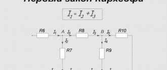
Kirchhoff's first law in complex form: The sum of the complex amplitudes of the currents of the branches converging at a node is equal to zero, i.e.
.
Since each term in the presented expression is a vector, the result is the sum of the vectors. This circumstance allows you to control analytical calculations with visual graphical constructions - vector diagrams.
Example 2
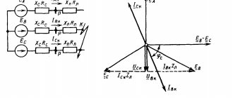
. At the electrical circuit node, 3 branches with sinusoidal currents of the same frequency converge (Fig. 3.3, a).
The instantaneous values of currents i 2 and i 3 are determined by the expressions i2= 100 Sin(100t-45o) and i3= 50 Sin(100t+30o). It is required to determine the current i1 using the complex amplitude method.
Solution.
Based on Kirchhoff’s first law in complex form, we find
, Where ,
Then
Having constructed the current vectors on the complex plane (Fig. 3.3, b), we are convinced that their sum is indeed equal to 0.
Passing from the complex to the instantaneous value, we obtain i1= 101 Sin(100t-74o), A.
Kirchhoff's second law in complex form - in a steady sinusoidal mode, the sum of the complex amplitudes of the EMF of the voltage sources in the circuit is equal to the sum of the complex amplitudes of the voltage drops on the circuit elements. If the circuit contains N voltage sources and L passive elements, then mathematically this position is formulated as follows:
.
Example 3
. The instantaneous voltage values on the circuit elements are known (Fig. 3.4, a) u1= 10 Sin(100t-45o) B, u2= 25 Sin(100t+30o)B, u3= 5 Sin(100t+60o)B. It is required to determine the instantaneous value of the emf of the voltage source.
Solution.
Based on Kirchhoff’s second law for instantaneous values of voltage and emf, we find e = u1+ u2+ u3.
Passing to complexes, we get
, Where
; ;
Hence,
=
By constructing the stress vectors on the complex plane (Fig. 3.4, b), we are convinced that their sum is indeed equal to the EMF vector. Moving from the complex to the instantaneous value, we obtain e = 32.3 Sin(100t+18o), V.
Method of complex amplitudes.
The complex amplitude method is a method for calculating linear radio circuits containing reactive elements in a steady state with harmonic input signals.
The essence of the method is as follows:
1) For all reactive elements, their complex impedance is determined.
2) All currents and voltages are considered in the form of complex amplitudes.
After introducing these substitutions, the problem of circuit analysis is reduced to the task of analyzing a DC circuit:
— impedances are treated as ordinary resistances;
- complex amplitudes of currents and voltages like ordinary currents and voltages.
This way we got rid of reactivity
elements and
time dependence of
signals. These factors, which complicate mathematical operations when describing the circuit, are now transferred to the signal: all parameters depend on the frequency of the harmonic signal and are complex-valued.
The problem of analyzing a DC circuit is solved by appropriate methods, for example, the method of nodal potentials or the method of loop currents. After finding all the desired complex amplitudes, they can be converted back into harmonic signals if necessary.
This method is used to calculate branched AC circuits containing reactance (capacitors and inductors). Resistance
these elements are written through complex numbers.
The capacitor resistance will be equal to: Zc=j/ωC,
inductance resistance: ZL=jωL,
where j is the imaginary unit instead of i, since i denotes the current,
ω – cyclic frequency, which is equal to 2πν,
C and L are capacitance and inductance, respectively.
The voltage source, taking into account the phase, is designated as Uejφ, where U is the effective voltage, φ is the phase of this source.
If a current source with a certain phase is given, then π/2 is subtracted from this phase to obtain the cosine phase of this source, and then through the resulting cosine phase, this source is written similarly to the voltage source: Iejφ.
If a capacitor is connected in series with a resistor, then their total resistance is written as R-jZc, if inductance, then the total resistance is equal to R+jZL.
Then the directions of currents in the circuit are conditionally selected, + and - are conditionally selected at the voltage and current sources, and equations are drawn up to calculate this circuit, best of all according to Kirchhoff’s rules (Kirchhoff’s first rule:
the sum of currents in all branches converging at a given node is equal to zero;
's second rule:
the sum of the voltage drops across all resistances is equal to the sum of all emfs in a given circuit) or using the method of nodal potentials:
1) Ohm's law for a section of a circuit containing EMF:
φ1 φ2
φ1 – node from which current flows;
φ2 – node to which the current flows;
V1 – source switched on in the direction of current;
V2 – source switched on opposite to the direction of current;
R1 – branch resistance.
2) Law of conservation of charge
:
Further, solving this system, we obtain complex values of the currents in the branches. To obtain the current values that ammeters will show, you just need to take the modules of these complex currents.
Example:
Let us calculate this circuit using the complex amplitude method using Kirchhoff’s rules.
Kirchhoff's laws and Ohm's law in complex form. Complex and total resistance and conductance
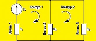
Let's consider an arbitrary circuit of an electrical circuit (Fig. 1.6).
Rice. 1.6 – Electrical circuit
According to Kirchhoff’s second law, the equality holds:
. (1.33)
Let us use correspondence (1.32) and rewrite this equality in the form:
or
Since this equality holds for any moment in time, the sign of the real part can be omitted:
or
, (1.34)
that is, the algebraic sum of the complex stress amplitudes on the circuit elements forming the circuit is equal to zero . This is the essence of Kirchhoff's second law in complex form . The sign of the complex amplitude is still determined by the coincidence or non-coincidence of the voltage direction with the selected direction of bypassing the circuit.
In a similar way, consider an arbitrary node in an electrical circuit (Fig. 1.7).
Rice. 1.7 – Electrical circuit assembly
According to Kirchhoff's first law, the equality holds:
. (1.35)
Let us use correspondence (1.32) and rewrite this equality in the form:
or
Since this equality holds for any moment in time, the sign of the real part can be omitted:
or
, (1.36)
that is, the algebraic sum of the complex amplitudes of the currents of the branches converging at any node of the electrical circuit is equal to zero . This is the essence of Kirchhoff's first law in complex form . The sign of the complex amplitude is still determined by the direction of the corresponding branch current: the “+” sign corresponds to the currents flowing into the node, and the “-” sign to the currents flowing from the node.
Let us similarly transform the component ratios for resistance, inductance and capacitance:
. (1.37)
Let us use correspondence (1.32) and rewrite these equalities in the form:
Since the operations of taking the real part, multiplying by a constant, differentiation and integration are linear, they are commutative and these equalities can be rewritten in the form:
Since this equality holds for any moment in time, the sign of the real part can be omitted. Then, after performing the operations of differentiation and integration, these expressions take the following form:
or
. (1.38)
These expressions reflect the essence of Ohm's law in complex form : the complex amplitude of the voltage in a given section of an electrical circuit is equal to the product of the complex amplitude of the current flowing through a given section and the complex resistance of that section.
Thus, the complex resistances of the resistive, inductive and capacitive elements are equal:
, , . (1.39)
When the elements of an electrical circuit are connected in series , the same current flows through them, and, therefore, the expressions for Ohm’s law in complex form will include the same complex current amplitude. On the other hand, the voltage at the ends of such a section is the sum of the voltages on the individual elements, and, therefore, the complex resistances of these elements also added up .
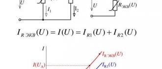
The reciprocal of complex resistance is called complex conductivity . It is obvious that when the elements of an electrical circuit are connected in parallel, the voltage at their terminals is the same, and, therefore, the expressions for Ohm’s law in complex form will include the same complex voltage amplitude. On the other hand, the current flowing to such a connection is the sum of the currents flowing through each of the connected elements, and, therefore, the complex conductivities of these elements also added up .
The complex conductivities of resistive, inductive and capacitive elements are determined by the expressions:
, , . (1.40)
The introduced complex resistance and conductivity have a certain physical meaning. Thus, the module of complex resistance of a certain section of an electrical circuit, which is called the total resistance of this section, determines the relationship between the amplitude of the voltage in this section and the current flowing through it. The complex resistance argument determines the phase shift between the voltage in a given section and the current flowing through it.
Let's consider examples of calculating linear electrical circuits within the framework of the complex amplitude method.
EXAMPLE 1
Let us define in general form the amplitudes and initial phases of voltages across resistance and inductance for the following electrical circuit:
The analyzed circuit can be considered as a two-terminal network, consisting of a series-connected resistance and inductance, to which an EMF source is connected.
The complex input impedance of this two-terminal network is equal to:
.
Using Ohm's law, we find the complex amplitude of the current in the circuit and the voltages on its individual elements:
,
where is the argument of the complex input resistance,
, (A1.1)
. (A1.2)
EXAMPLE 2
Let us define in general form the amplitudes and initial phases of voltages across the resistance and capacitance for the following electrical circuit:
The circuit is a two-terminal network consisting of a resistance and capacitance connected in series, to which an EMF source is connected.
The complex input impedance of this two-terminal network is equal to:
.
Using Ohm's law, we find the complex amplitude of the current in the circuit and the voltages on its individual elements:
,
where is the argument of the complex input resistance,
, (A2.1)
. (A2.2)
EXAMPLE 3
Let us define in general form the amplitudes and initial phases of voltages across resistance, inductance and capacitance for the following electrical circuit:
We find the complex input resistance:
, or
,
where is the reactive component of the complex input resistance.
Using Ohm's law, we find the complex amplitude of the current in the circuit and the voltages on its individual elements:
,
where is the argument of the complex input resistance,
, (A3.1)
, (A3.2)
. (A3.3)
3
System of Protected Areas in the USA The study of specially protected natural areas (SPNA) in the USA is of particular interest for many reasons...
Conflicts in family life. How can I change this? It is rare that a marriage and relationship exists without conflict and tension. Everyone goes through this...
What Causes Trends in Stock and Commodity Markets Freight Train Theory Explained My first 17 years of market research consisted of trying to figure out when...
WHAT AND HOW THEY WRITTEN ABOUT FASHION IN MAGAZINES AT THE BEGINNING OF THE XX CENTURY The first issue of the Apollo magazine for 1909 began, in fact, with a policy statement from the magazine’s editors...
Didn't find what you were looking for? Use Google search on the site: