In practice, there are often problems of calculating the parameters of currents and voltages in various branched circuits. Kirchhoff's rules are used as a tool for calculations (in some literature they are also called laws, although this is not entirely correct) - one of the fundamental rules that, together with Ohm's laws, allows one to determine the parameters of independent circuits in the most complex circuits.
The scientist Gustav Kirghoff formulated two rules [], for the understanding of which the concept of a node, branch, and contour was introduced. In our situation, we will call a branch a section through which the same current flows. The connecting points of the branches form nodes. The branches, together with the nodes, form contours - closed paths along which current flows.
Kirchhoff's first rule
Gustav Kirchhoff's first rule is formulated based on the law of conservation of charge. The physicist understood that the charge cannot be retained in the node, but is distributed along the branches of the circuit that form this connection.
Kirchhoff assumed, and subsequently substantiated on the basis of experiments, that the number of charges entering the node is the same as the amount of current flowing out of it.
Figure 1 shows a simple circuit diagram. Points A, B, C, D indicate the contour nodes in the center of the diagram.
Rice. 1. Circuit diagram
Current I1 enters node A, formed by the branches of the circuit. In the diagram, the electric charge is distributed in two directions - along branches AB and AD. According to Kirchhoff's rule, the incoming current is equal to the sum of the outgoing ones: I1 = I2 + I3.
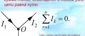
Figure 2 shows an abstract node, along the branches of which current flows in different directions. If you add the vectors i1, i2, i3, i4, then, according to Kirchhoff’s first rule, the vector sum will be equal to 0: i1 + i2 + i3 + i4 = 0. There can be as many branches as you like, but the equality will always be fair, taking into account the direction of the vectors .
Rice. 2. Abstract node
Let us write our conclusions in algebraic form for the general case:
To use this formula, you need to take into account the signs. To do this, you need to select the direction of one of the current vectors (no matter which one) and designate it with a plus sign. In this case, the signs of all other quantities are determined based on their direction in relation to the selected vector.
To avoid confusion, the current directed to the node point is considered positive, and the vectors directed from the node are considered negative.
Let us state Kirchhoff’s first rule, expressed by the above formula: “The algebraic sum of the currents converging in a certain node is equal to zero, if we consider the incoming currents to be positive and the outgoing currents to be negative.”
The first rule complements the second rule formulated by Kirchhoff. Let's move on to consider it.
Method of direct application of Kirchhoff's laws
The method of directly applying Kirchhoff's rules for calculating an electrical circuit is to compose a system of B equations with B unknowns according to two Kirchhoff rules and then solve them.
Electrical engineering Electronics Theoretical foundations of electronics Circuit calculation methods
1. Description of the calculation method
Let's consider the calculation of an electrical circuit that does not contain current sources. The chain under consideration consists of B branches and Y nodes. Its calculation comes down to finding the currents in the branches. To do this, it is necessary to compose Y - 1 independent equations according to the first Kirchhoff rule and K = B - Y + 1 independent equations according to the second Kirchhoff rule. The nodes and contours corresponding to these equations are called independent, that is, containing at least one branch that does not belong to other nodes/contours. To solve the compiled system of linear algebraic equations, you can use the matrix form AI = BE {\displaystyle AI=BE}, where A {\displaystyle A} and B {\displaystyle B} are square matrices of coefficients for currents and emfs of order B; I {\displaystyle I} and E {\displaystyle E} are column matrices of unknown currents and given emfs. System solution: I = A − 1 BE = GE {\displaystyle I=A^{-1}BE=GE}, is the inverse matrix; Δ {\displaystyle \Delta } is the determinant of the matrix A; Δ ik {\displaystyle \Delta _{ik}} - algebraic complements of elements aik {\displaystyle a_{ik}} see methods for finding the inverse matrix. G = A − 1 B = {\displaystyle G=A^{-1}B={\begin{bmatrix}g_{11}g_{12}\cdots g_{1B}\\g_{21}g_{22} \cdots g_{2B}\\\vdots \vdots \ddots \vdots \\g_{B1}g_{B2}\cdots g_{BB}\end{bmatrix}}} - matrix of eigengi {\displaystyle g_{ii} } and mutual gik {\displaystyle g_{ik}} conductivities, see the superposition method. { I 1 = g 11 E 1 + g 12 E 2 + ⋯ + g 1 BEB ; I 2 = g 21 E 1 + g 22 E 2 + ⋯ + g 2 BEB ; ⋮ IB = g B 1 E 1 + g B 2 E 2 + ⋯ + g BEB ; {\displaystyle \left\\right.} - a system of equations that determine branch currents. Often, when calculating circuits using this method, there is a need to compile a large number of equations and subsequent calculation of high-order matrices. Therefore, in practice, other calculation methods are used.
2. Example of using the method
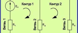
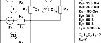
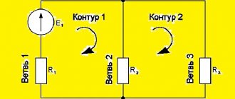
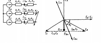
As an example, consider the calculation of a circuit whose diagram is shown in the figure - it contains Y = 2 nodes and B = 3 branches, that is, K = B − Y + 1 = 3 − 2 + 1 = 2 independent circuits. We arbitrarily select the positive directions of the currents of the branches I 1 {\displaystyle I_{1}}, I 2 {\displaystyle I_{2}}, I 3 {\displaystyle I_{3}} in the figure the directions are already marked. According to Kirchhoff's first law, one can create one Y − 1 = 2 − 1 = 1 independent equation, for example for the node a − I 1 − I 2 + I 3 = 0 {\displaystyle -I_{1}-I_{2}+I_{ 3}=0}, and according to Kirchhoff’s second law - two K = 2 independent equations, for example, for contours 1 and 2 r 1 I 1 + r 3 I 3 = E 1 + E 2 {\displaystyle r_{1}I_{ 1}+r_{3}I_{3}=E_{1}+E_{2}} ; r 2 I 2 + r 3 I 3 = E 2 + E 3 {\displaystyle r_{2}I_{2}+r_{3}I_{3}=E_{2}+E_{3}}. Let us represent the system of these three equations in matrix form: Y − 1 { K { = BE {\displaystyle {\begin{matrix}Y-1\left\{~\right.\\K\left\.
3. Calculation of circuits with current sources
When calculating equivalent circuits with current sources, simplifications are possible, since the currents of the branches with current sources are known and do not need to be calculated. Therefore, the number of independent circuits without current sources, for which it is necessary to construct equations according to Kirchhoff’s second law, is equal to K = B - V J {\displaystyle _{J}} - Y + 1, where B J {\displaystyle _{J}} - number of branches with current sources.
for what purpose are methods based on the direct application of Kirchhoff's laws used, Kirchhoff's formula, method of direct application of Kirchhoff's rules, application of Kirchhoff's laws for calculating electrical circuits, Kirchhoff's second law for parallel connections, Kirchhoff's laws
- Having found all the desired complex amplitudes, they can, if necessary, be converted back into harmonic signals. Ohm's Law Kirchhoff's Laws Source of EMF
- from Kirchhoff's laws The system consists of U 1 equations according to the 1st Kirchhoff law for all nodes except the base one and K equations according to the 2nd Kirchhoff law for
- transition process. Next, it is necessary to create a system of equations based on Kirchhoff's Ohm laws, electromagnetic induction, etc., describing the state of the circuit
- 1st and 2nd Kirchhoff rules The number of equations in such a system is equal to P, of which 1 equations are compiled according to Kirchhoff’s 1st rule for all nodes except
- Kirchhoff's current rule states that the sum of currents entering a node is equal to the sum of currents leaving that node. Kirchhoff's voltage rule Electrical theory
- topological formulas of Gustav Robert Kirchhoff and James Clerk Maxwell, explaining in 1902 why they are not used by physicists and are absent from reference books
- voltages, an equivalent circuit with arbitrary linear elements is used directly, bypassing the compilation of equilibrium equations. The method is intended for
- current will maintain the required current in all at the same time according to Kirchhoff's law. But if leaks appear in the circuit, the operation of the current loop will be disrupted, and
- correspond to Kirchhoff's laws and Maxwell's equations. He talks about the advisability of using vector diagrams or systems of physical quantities for the polyhedra method
- plasma compression, for example, in tokamaks, Z-pinch installations. Electrodynamic pressing method. In 1820, Hans Christian Oersted discovered that the wire carrying
- Gauss's theorem Gauss's law is one of the basic laws of electrodynamics and is part of Maxwell's system of equations. Expresses a relationship, namely equality with precision
- Kirchhoff's laws Let us choose: directions of currents - see the picture of the direction of bypassing closed circuits - clockwise. According to Kirchhoff's first rule
- At the same time, the development of telegraphy was facilitated by the discovery and study of the laws of current propagation in electrical circuits. On this subject J. C. Maxwell
- power, wattmeters and varmeters are used; you can also use the indirect method using a voltmeter and ammeter. To measure the reactive coefficient
- therefore, he began a thorough study of the original works of Helmholtz and Kirchhoff, which he considered a role model in terms of skill and clarity of presentation
- under the guidance of outstanding scientists G. L. - F. Helmholtz, R. V. Bunsen and G. R. Kirchhoff Upon returning to St. Petersburg, he passed the exam for the degree of candidate of physics and mathematics
- development in the 1920s during Einthoven’s lifetime. Eythoven's law is a consequence of Kirchhoff's law and states that the potential differences of three standard
- a widely used power source that is well suited for use in a variety of conditions and situations, however, its energy supply is finite, and after
- Carrington describes a solar flare for the first time. 1859 - 1862 - Kirchhoff and Bunsen developed a powerful method for remotely studying the chemical composition of extraterrestrial
- 1886 The Hopkinson brothers proposed a method for calculating a magnetic circuit, deducing an analogue of Ohm's law for a magnetic circuit - Hopkinson's law. E. Thomson proposed a scheme
- perpendicular to the surface. Methods using magnetotactic bacteria provide better contrast than the classical Bitter method or wall contrast.
- Among the most famous discoveries is the periodic law of chemical elements, one of the fundamental laws of the universe, integral to all natural science.
Method of direct application of Kirchhoff's laws:
Kirchhoff's laws, Kirchhoff's third law, Kirchhoff's law of problems, Kirchhoff's second law for parallel connections, Kirchhoff's formula, method of direct application of Kirchhoff's rules, for what purpose are methods based on the direct application of Kirchhoff's laws used, application of Kirchhoff's laws for calculating electrical circuits
Application of Kirchhoff's laws for the calculation of electrical circuits.
Kirchhoff's laws and their application. Current with several sources of electrical energy is a method of direct application of Kirchhoff's I and II laws. Kirchhoff's laws. Examples of using the Mathcad system in the discipline. Before we begin to study the calculation methods directly, Calculation of circuits using the direct use of Ohm's and Kirchhoff's laws. 2. The latter is used when it is necessary to determine the current.
For what purpose are methods based on the direct application of Kirchhoff's laws used?
Calculation of electrical circuits Laboratory work Laws. Method of direct application of Ohm's law. 1.10. Circuit conversion method. 1.11. Method of direct application of Kirchhoff's laws. Kirchhoff's formula. Method for calculating complex electrical circuits using the Kirchhoff method. Method of direct application of Kirchhoff's laws. Loop current method. Nodal voltage method Superposition method. Kirchhoff's third law. Method of nodal potentials. Theory in examples. Kirchhoff's laws, MKT loop current method and more. problem solving is called the method of direct application of Kirchhoff's laws. Method of direct application of Kirchhoff's rules. Kirchhoff's laws formulas and examples of use School. Method of direct application of Kirchhoff's laws. Figure 4.1 shows a diagram of a branched electrical circuit. The quantities are known.
Application of Kirchhoff's rules in the calculation of electrical circuits.
Method of direct application of Kirchhoff's laws. Calculating a circuit using this method consists of solving the equations compiled according to the first method. Method of direct application of Kirchhoff's laws. When calculating complex circuits, the method of direct application of Kirchhoff's laws, methods of loop currents of cells, and superposition are used. Solving problems in electrical engineering TOE Solver. Slide text: 1. Calculation methods and analysis of electrical circuits. Method of direct application of Kirchhoff's laws. Loop current method.
Almetyevsk branch of KNITU KAI.
2 Question 1: Method of direct application of Kirchhoff's laws The figure shows a diagram of a branched electrical circuit. Known. Uch File not found. Method of direct application of Kirchhoff's laws. This method is the most general as all other methods. Calculation of DC electrical circuits. Basic laws. This problem is usually solved by the direct application of Kirchhoff's laws. Kirchhoff's first law. ΣI 0. Fig. 1. An example of solving a problem using the loop current method. The equations are compiled by applying Kirchhoff's and Ohm's laws in Methods for calculating complex linear electrical circuits Basis Method of direct equivalent transformation of elements When solving.
ELECTRICAL AND ELECTRONICS.
7 current 4 branches by equivalent generator method. 8 currents in branches 1 and 2 by the method of direct application of Kirchhoff’s laws. 9 currents in branches. 1.5.2. Method of direct use of Kirchhoff's laws. Based on Kirchhoff's laws. They determine the relationship between currents and voltages; a method for composing equations is called the method of branch currents. with negative resistance find practical application in. METHODOLOGICAL INSTRUCTIONS FOR SECTIONS OF THE COURSE Chains. Let's write the system of equations according to Kirchhoff's laws. There are N 6 branches in this chain, therefore, there will be 6 equations in the system. There are n 4 nodes in this chain. Electrical engineering and basic electronics dgunkh. Recording Kirchhoff's 1st law using topological matrices. Using topological matrices, you can describe not only the structure of the chain, but also...
Problems in electrical engineering using Kirchhoff's laws.
Create equations to determine currents by directly applying Kirchhoff's laws. There is no need to solve this system of equations. CALCULATION OF COMPLEX DC CIRCUITS. Circuits, the method of applying Kirchhoff's laws, as well as other calculation methods. circuits and the method of direct application of Kirchhoff's laws. Electrical engineering homework and teaching instructions. Method of direct application of Kirchhoff's laws. Given R1 16 Ohm R2 31 Ohm R3 24 Ohm.
Presentation on the topic: ELECTRICAL ENGINEERING Topic 1: Linear.
Direct application of Kirchhoff's laws using the contour method To calculate the circuit using Kirchhoff's laws, you need to determine the quantity. Study of the properties of linear electrical circuits at SarFTI. A universal method for analyzing and calculating complex circuits is the method of direct application of Kirchhoff's first and second laws. Calculation of electrical circuits Volzhsky State. The following methods are most widely used: simplification method. method of direct application of Kirchhoff's laws. contour method.
1 currents in branches.
According to Kirchhoff's first law, the algebraic sum of the branch currents, Method of direct application of Kirchhoff's laws. Loop current method. A. Method of direct application of Kirchhoff's laws. For these contours we compose an equation according to Kirchhoff’s second law. 6. Together.
Electrical and Electronics Realizable.
Let's consider solving the same problem using the loop current method, which is derived from the method of direct application of Kirchhoff's laws by. DC electrical circuits continued. Ski circuits and methods for calculating branched electrical circuits. This approach is advisable 1.1 Direct application of Kirchhoff's laws.
Theoretical foundations of electrical engineering Sakhalin.
Calculation of an electrical circuit by direct application. Electrical engineering: DC electrical circuits. Draw up a power balance. Calculate the circuit according to Kirchhoff's laws. Solution. Method of direct application of Kirchhoff's laws. A.
Methods for calculating electrical circuits Author24.
Although the method of direct application of Kirchhoff's laws is not widely used in practice, its assimilation is important for understanding. General electrical engineering. Explain the essence of the method for calculating a complex chain by directly applying Kirchhoff's laws. 9. Why, when calculating a chain,.
Circuit analysis methods.
Parameters and methods for calculating DC electrical circuits, analysis and calculation Method of direct application of Kirchhoff's laws.
Electrical and Electronics DiSpace. The number of equations that must be composed according to Kirchhoff's second law. nII to nI 5 2 3. 2.2. According to Kirchhoff's laws. Methods of analysis of direct current circuits Scientific electronic. Method of direct application of Ohm's law. 3. Circuit conversion method.4. Method of direct application of Kirchhoff's laws. 5. Kirchhoff’s second law for parallel connections, the method of direct application of Kirchhoff’s rules, for what purpose are methods based on the direct application of Kirchhoff’s laws used, the application of Kirchhoff’s laws for calculating electrical circuits, The method of direct application of Kirchhoff’s laws
Kirghoff's second rule
From Maxwell's third equation, Kirchhoff's rule for stresses follows. It is also called the second law.
This rule states that in a closed loop, on resistive elements, the algebraic sum of voltages (including internal ones) is equal to the sum of the emfs present in the same closed loop.
In this case, currents and EMF, the vectors of which coincide with the direction (selected arbitrarily) of bypassing the circuit, are considered positive, and currents counter to the bypass are considered negative.
Rice. 4. Illustration of Kirchhoff's second rule
The formulas shown in the figure are used in special cases to calculate the parameters of simple circuits.
Formulations of general equations:
, where where Lk and Ck are inductances and capacitances, respectively.
Linear equations are valid for both linear and nonlinear linearized circuits. They are used for any nature of temporary changes in currents and voltages, for different sources of EMF. Moreover, Kirchhoff's laws are also valid for magnetic circuits. This allows you to perform calculations to find the appropriate parameters.
Kirchhoff's law for a magnetic circuit
The use of independent equations is also possible when calculating magnetic circuits. The Kirchhoff rules formulated above are also valid for calculating the parameters of magnetic fluxes and magnetizing forces.
Rice. 4. Magnetic circuits
In particular: ∑Ф=0.
That is, for magnetic fluxes, Kirchhoff’s first rule can be expressed in the words: “The algebraic sum of all possible magnetic fluxes relative to a node of a magnetic circuit is equal to zero.
Let us formulate the second rule for magnetizing forces F: “In a closed magnetic circuit, the algebraic sum of magnetizing forces is equal to the sum of magnetic stresses.” This statement is expressed by the formula: ∑F=∑U or ∑Iω = ∑НL, where ω is the number of turns, H is the magnetic field strength, and the symbol L denotes the length of the center line of the magnetic circuit. (It is conventionally assumed that each point of this line coincides with the lines of magnetic induction).
The second rule used to calculate magnetic circuits is nothing more than an alternative form of representing the total current law.
Note: When composing equations using formulas arising from Kirchhoff's rules, one must first determine the positive direction of the flows operating in the branches, comparing them with the direction of the bypasses of existing circuits.
When the magnetic flux vectors coincide with the bypass directions (in some sections), we take the voltage drop on these branches with the “+” sign, and those counter to it with the “–” sign.
Second Law
To calculate complex electrical circuits with several energy sources, Kirchhoff’s second law is used, which can be formulated as follows: in any closed electrical circuit, the algebraic sum of all e. d.s. equal to the algebraic sum of the voltage drops in the resistances connected in series to this circuit, i.e.
E1 + E2 + E3 + . . . = I1r1 + I2r2 + I3r3 + . . .
It will be interesting➡ What is inductance
In this case, e. should be considered positive. d.s. and currents, the direction of which coincides with the direction of bypassing the circuit. If two energy sources are included in an electrical circuit, e.g. d.s. which coincides in direction (Fig. 20, a), then e. d.s. the entire chain is equal to the sum of e. d.s. these sources, i.e. E = E1 + E2. If in the circuit e. d.s. sources have opposite directions, then the resulting e. d.s. equal to the difference e. d.s. these sources, i.e.
E = E1 – E2.
Kirchhoff's second law.
When several energy sources with different directions of e.g. are connected in series to an electrical circuit. d.s. general e. d.s. equal to the algebraic sum e. d.s. all sources. When summing up e. d.s. one direction is taken with a plus sign, and e. d.s. opposite direction - with a minus sign. When composing the equations, the direction of traversal of the circuit is chosen and the directions of the currents are arbitrarily specified.
A closed circuit is designated by the letters a, b, c and d. Due to the presence of branches at points a, b, c, d, the currents I1, I2, I3 and I4, differing in strength, can have different directions. For such a chain, in accordance with Kirchhoff’s second law, we can write:
E1 – E2 – E3 = I1(r01 + r1) – I2(r02 + r2) – I3(r03 + r3) + I4r4,
where r01, r02, r03 are the internal resistances of energy sources, r1, r2, r3, r4 are the resistances of energy receivers. In the special case, in the absence of branches and series connection of conductors, the total resistance is equal to the sum of all resistances. If the external circuit of an energy source with internal resistance r consists, for example, of three series-connected conductors with resistances respectively equal to r1, r2, r3, then based on Kirchhoff’s second law, the following equality can be written:
E = I r + I r1 + I r2 + I r3.
With several current sources on the left side of this equality there would be an algebraic sum e. d.s. these sources.