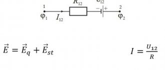
In each electrical circuit there are so-called P - edges (they are also branches, links, sections) and U - nodes. To describe it, there is a system of equations that use two Kirchhoff rules. In them, the edge currents act as independent variables. Therefore, the number of independent variables will be equal to the number of equations, which makes it possible to resolve the given system normally. In practice, methods are used aimed at reducing the number of equations. Among them, the loop current method is very often used, which allows you to perform calculations and obtain accurate results.
The essence of the loop current method
The basic principles of this method are based on the fact that the currents flowing in the edges of the circuit are not all considered independent. The equations for the nodes present in the U-1 system clearly show the dependence of the U-1 currents on them. When an independent current R-U+1 is isolated in the electrical circuit, the entire system can be reduced to the equations R-U+1. Thus, the loop current method is a very simple and convenient selection of independent currents P-U+1 in a circuit.
The use of this calculation method allows for the circulation of a certain virtual circuit current in each independent circuit P-U+1. If any edge belongs to only one specific circuit, then the value of the real current flowing in it will be equal to the circuit current. In the case when an edge is part of several circuits at once, the current flowing in it will be a sum that includes the corresponding circuit currents. In this case, the direction of traversing the contours must be taken into account. Independent circuits cover almost the entire circuit, so the current flowing in any edge can be expressed in terms of circuit currents that make up the complete system of all currents.
Kirchhoff's law - calculation and application
In order to build a system of independent contours, a simple and visual method of creating planar graphs is used. In this diagram, the branches and nodes of the chain are placed on the plane in such a way that mutual intersection of edges is completely eliminated. Using this method, the plane is divided into regions bounded by closed chains of edges. It is they who make up the system of independent circuits. This method is most suitable for manual circuit calculations. However, its application may become difficult or even impossible if the scheme in question does not fit into the framework of a planar graph.
Calculation of electrical circuits online using the loop current method
Calculation using the loop current method has appeared in the online calculation program for electrical circuits.
The calculation method is selected in the drop-down list. To calculate using the loop current method, you must select the “MKT” calculation method. The methodology used for calculations using the nodal potential method is given here.
Example diagram and calculation:
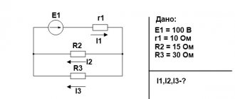
Initial data and diagram:
- E1: Item number: 1
- Amplitude value: 100 V
- Initial phase, °: 0
- Item number: 1
- Item number: 1
- Item number: 1
After clicking the “Calculation” button, the numbering of nodes appears on the original diagram and a solution is generated:
Let's calculate the circuit using the loop current method.
In this scheme: nodes - 2, branches - 3, independent circuits - 2.
The number of equations compiled using the loop current method is equal to $ N_\textrm{v}- N_\textrm{y} + 1 $, where $ N_\textrm{y} $ is the number of branches without current sources, $ N_\textrm{y } $ − number of nodes.
For this circuit, the number of equations compiled using the loop current method is 3 − 2 + 1 = 2.
Let us arbitrarily set the directions for bypassing the circuits and the corresponding circuit currents.
Accepted directions for traversing contours: Contour No. 1 is traversed through the elements $ \underline{E}_{1} $, $ R_{1} $, $ L_{1} $ in the specified order. A loop current $ \underline{I}_{11} $ flows through these elements. Circuit No. 2 is traversed through the elements $ L_{1} $, $ C_{1} $ in the specified order. A loop current $ \underline{I}_{22} $ flows through these elements.
Let's compose equations using the loop current method.
Let's create an equation for circuit No. 1:
$$ \underline{I}_{11} \cdot (R_{1}+jX_{L1})+\underline{I}_{22} \cdot jX_{L1}=\underline{E}_{1} $$
Let's create an equation for circuit No. 2:
$$ \underline{I}_{22} \cdot (jX_{L1}- jX_{C1})+\underline{I}_{11} \cdot jX_{L1}=0 $$
Let us combine the resulting equations into one system, and at the same time transfer the known quantities to the right side, leaving only the components with the desired loop currents on the left side. The system of equations using the loop current method for the original circuit is as follows:
$$ \begin{cases}\underline{I}_{11} \cdot (R_{1}+jX_{L1})+\underline{I}_{22} \cdot jX_{L1} = \underline{E }_{1} \\ \underline{I}_{22} \cdot (jX_{L1}- jX_{C1})+\underline{I}_{11} \cdot jX_{L1} = 0 \\ \ end{cases} $$
Let us substitute the values of resistances and sources into the resulting system of equations and obtain:
$$ \begin{cases}(1+1j)\cdot \underline{I}_{11}+ j \cdot \underline{I}_{22}=100 \\ j \cdot \underline{I}_{ 11}=0 \\ \end{cases} $$
Let us solve the system of equations and obtain the desired loop currents:
$$ \underline{I}_{11} = 0\space\textrm{A} $$
$$ \underline{I}_{22} = -100j\space\textrm{A} $$
Let us arbitrarily set the directions of the currents in the branches.
Accepted directions of currents: Current $ \underline{I}_{1} $ is directed from node '2 y.' to node '1 y.' through the elements $ \underline{E}_{1} $, $ R_{1} $. Current $ \underline{I}_{2} $ is directed from node '1 y.' to node '2 y.' through the elements of $L_{1}$. Current $ \underline{I}_{3} $ is directed from node '1 y.' to node '2 y.' through the elements of $C_{1}$.
Let's calculate the currents in the branches based on the obtained loop currents.
$$ \underline{I}_{1} =\underline{I}_{11}=0=0 $$ $$ \underline{I}_{2} =\underline{I}_{11}+\ underline{I}_{22}=0+(-100j)=-100j $$ $$ \underline{I}_{3} =-\underline{I}_{22}=-(-100j)=100j $$
After the calculation is completed, vector diagrams of currents and voltages are also displayed on the screen.
Recommended Posts
- Calculation of electrical circuits online using the nodal potential method.
Calculation using the nodal potential method has appeared in the online calculation program for electrical circuits. The choice of calculation method is carried out in… - Loop current method for calculating electrical circuits When calculating electrical circuits, in addition to Kirchhoff's laws, the loop current method is often used. Loop current method...
- Calculation of electrical circuits using the method of nodal potentials: conclusion of the method Along with solving electrical circuits according to Kirchhoff’s laws and the method of loop currents, the method of nodal...
Kirchhoff's laws. Calculation of DC circuits
In electrical engineering, there are two basic laws, on the basis of which, theoretically, all circuits can be solved.
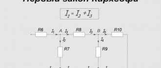
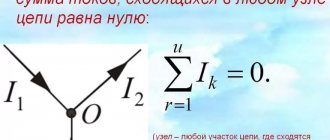
Kirchhoff's first law is as follows. The sum of currents entering a node is equal to the sum of currents leaving the node.
For this figure we have: I1 + I2 + I4 = I3 + I5.
Kirchhoff's second law . The sum of voltages along a closed loop is equal to the sum of the emf along the same loop. For the diagram in the figure (we denote the direction along the contour with an arrow, which we will consider conditionally positive).
Starting from the node where the currents I1, I3, I4 converge, we write down all the voltages (according to Ohm’s law): -I1⋅R1 - I1⋅R2 - in the first branch (the minus sign means that the current is in the opposite direction to the selected direction of the circuit). I3⋅R3 – in the second branch (plus sign, the direction is the same).
Now let's write down the EMF: E2 - E3 (the minus sign at E3, because the direction of the EMF is opposite to the direction of the circuit).
In accordance with Kirchhoff's law, the voltages are equal to the emf: -I1⋅R1 - I1⋅R2 + I3⋅R3 = E2 - E3.
As you can see, everything is quite simple.
In most cases, students are faced with the task of calculating the current values in all branches, knowing the values of the emf and resistors. To calculate a complex, branched DC circuit, such as this one found on the Internet, we will use the following steps.
To begin with, we set conditionally positive directions of currents in the branches (this means that the current can flow in the opposite direction, then it will have a negative value).
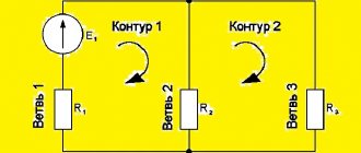
We compose a system of equations according to Kirchhoff’s second law for each closed circuit so as to cover each unknown current (in this circuit we have 3 such circuits). For convenience, we select the directions of the contours clockwise (although this is not necessary):
According to Kirchhoff’s first law, we compose so many equations to cover all unknown currents (in this diagram for any three nodes):
In total, we have a system of 6 equations. To solve such a system, you can use the MathCad program. It is solved as follows:
This is a screenshot of the program. The equal sign in equations should be bold (Boolean tab, CTRL + “=/+”). MathCad can solve systems of any order (for example, a circuit has 10 independent circuits). But, firstly, the “Given” function does not work with complex numbers (more on this later), and secondly, you don’t always have a computer at hand or the condition of the problem is set in such a way that you need to solve the circuit using another method.
This method of solving problems is called the method of direct application of Kirchhoff's laws . Most senior students (who have already taken the TOE course), electrical engineers, even teachers and doctors of science can solve circuits only with this method, because other methods are used extremely rarely.
Calculation of the electric circuit of direct current ENU
Tasks for students’ independent work
Task 1 Calculation of a DC electrical circuit
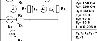
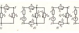
1. For the electrical circuit shown in Fig. 0, using the given resistances and emf, find all currents in the following ways:
a) using Kirchhoff’s laws;
b) loop current method;
c) nodal stress method;
d) determine the current in resistor R6 using the equivalent generator method.
Summarize the calculation results into one table.
2. Determine the voltmeter reading.
3. Draw up a power balance.
Download DC electrical circuit calculation
Task Calculation of a DC electrical circuit
Alternating current.
The circuit must maintain a power balance, that is, the energy given by the sources must be equal to the energy received by the receivers.
The last step is to find the real currents; to do this, you need to write down expressions for them. The operation of an active two-terminal network under load in nominal mode is determined by equation 1.
Let us determine the parameters of the electrical circuit in Fig. Uncontrolled nonlinear elements have one current-voltage characteristic; controlled - a family of characteristics.
Determine the current I1 in a given circuit with a current source using the equivalent generator method. To solve such a system, you can use the MathCad program. The circuit must maintain a power balance, that is, the energy given by the sources must be equal to the energy received by the receivers. You can collapse a circuit using equivalent transformations of serial, parallel, and mixed connections.
Read more: Standards for laying cables underground
AGZ EMERCOM RGR No. 1 Calculation of linear DC circuits
Equations according to the second law are made for independent contours. Let us determine the parameters of the electrical circuit in Fig. The loop current is equal to the actual current that belongs only to this loop. You can collapse a circuit using equivalent transformations of serial, parallel, and mixed connections.
The direction of the circuit bypass coincides with the direction of the circuit currents. Operating mode of the electrical circuit Fig. An alternating sinusoidal current or voltage is given by the equation: Here Im is the amplitude of the current. For example, using Kirchhoff's law, which states that the sum of the emf in the circuit is equal to the sum of the voltages in it. The method of loop currents is that instead of currents in the branches, the so-called loop currents that close in the loops are determined, based on Kirchhoff’s second law.
Determine the currents in all branches of the circuit based on the superposition method.
This current-voltage characteristic is plotted using two points 1 and 2 in Fig. To do this, you need to find the voltage in the circuit, which will be common to both resistors, since the connection is parallel. Therefore, the current source circuit Fig. Let's calculate the similarity coefficient.
Draw up a power balance in the original circuit with a current source, calculating the total power of the sources and the total power of the resistance loads. It is recommended to replace circuit nodes a, b, c, d with 1, 2, 3, 4, respectively. The exception is circuits containing more complex star and delta connections. In our case, these currents are directed clockwise. Kirchhoff's Laws - Theory and Problem