Laying beams in a brick wall
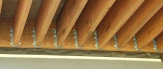
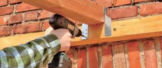
The main reasons for strengthening floors are poor load-bearing capacity, the need to increase the load when building additional attributes, for example, a chimney for a future fireplace. As well as unsatisfactory technical condition, the cause of which is damage to the beams or improper support on the walls. This article will describe the main type of beam fastening, their step-by-step installation and recommendations, as well as the arrangement of supports for the construction of a chimney. In order to support the beams on brick walls, steel supports are used. This type of construction work assumes that the ends of the beam have the ability to deform, that is, at the moment of sagging, they must rotate and also shift along the longitudinal axis under the influence of high temperatures. At the moment when the floors are supported on a brick wall, there must be a ventilated pneumatic gap between the frontal plane and the vault beam.
To achieve this result, movable and fixed sleepers are used. In this case, use of the premises will be safe and reliable, and will also avoid additional pressure.
Equipping the connection between the floor and the base is the most important function of installing beams, which connects it to the wall or columns. Also a significant factor in this process, which guarantees the reliability and strength of the constructed connection between the floor and the support, are: an acceptable choice of support device, as well as the depth to which these beams are embedded, followed by anchoring into the wall.
Beam support for mounting on brickwork
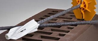
SFH Safety Fast Hangers are an innovative range of supports designed to secure timber beams, trusses/trusses to masonry walls without the need for masonry above the support. Does not require masonry above the connector to achieve the specified load-bearing ratings. Provides improved distribution of vertical and horizontal loads.
- Technical description
- Buy online
Characteristics
Characteristics
Material
- Galvanized steel S250GD. Coating Z275, in accordance with EN 10346B, belongs to the second category of operation.
- The thickness of the zinc coating is 20 μm.
Advantages
- Does not require finishing the masonry above the connector to achieve the specified tabulated load-bearing capacity values.
- Provides improved distribution of vertical and horizontal loads.
- The mini-sling is attached to a support on one side and a beam on the other.
- Using a support allows you to install the interfloor ceiling before the masonry above the support itself is completed.
- SFH/SFHI eliminates the need for support posts.
- The mini sling provides lateral pinch in accordance with NHBC regulations.
- Allows lateral pinching and makes the connection more reliable and secure.
- Technical Data
- Installation
- Technical drawing
Support unit
When supporting metal floor beams on brick walls for supporting purposes, it is first important to decide on a plan for the structural arrangement of the location of the nodes. The selection of methods for forming nodes depends on the support pressure generated under the end of the partition. The metal beam must rest on the brick walls through metal or reinforced concrete load distribution pads.
The hinged support unit provides for the arrangement of the crossbar directly on the brick base through a 15-centimeter cushion of cement-sand mass. In this case, the maximum pressure under the end of the partition built into the wall is distributed to the wall base through steel support plates having a height of 2 cm.
When the supporting load exceeds 10 tons, the reinforced concrete floors are equipped with a distribution pad, the minimum thickness of which is 10 cm. In addition, the crossbar is reinforced with a double reinforced mesh. It is prohibited to support a load-bearing steel beam on the brick wall itself in such conditions. With this method of arrangement, the support nodes are formed rigid.
It makes sense to use hollow-core reinforced concrete slabs when building a high-rise building.
Properly performed minimal support of the floor slab on a brick wall ensures the strength and durability of the finished structure. When constructing a multi-storey building, hollow reinforced concrete slabs are laid between floors. The thickness of the slab ranges from 16-33 mm, length - 1.5-12 m. In this case, the minimum length of support of the end part of the hollow-core slab on the brick base is 9 cm. To obtain more accurate data, a calculation is made.
Defects and their consequences
When there is a displacement of the axis of the beam (crossbar) from the axis of the column, additional forces appear in the column of bending moments, which act in the perpendicular direction relative to the plane of the transverse frames. The consequence of such defects is a decrease in the bearing capacity of the columns.
If there is a displacement of the beam (crossbar) in the plane of the transverse frames, then one of the platform supports will have a shorter length when compared with the design one.
This can cause pulling of the reinforcement (longitudinal), the appearance of cracks and destruction of the beam (crossbar). And also, since the support area is small, concrete destruction at the point of support is possible, since it is crushed or chipped.
- Another defect involves the deviation of the beam (crossbar), or rather its plane, from the vertical. This becomes possible as a result of the skew of the supporting part in the beam. As a result, torques appear for which the beam (crossbar) design is not designed.
- Basically, all of the above defects can also occur when performing installation work on installing a reinforced concrete truss. The consequences caused by these defects (during installation of the truss) are also similar to those mentioned above.
- I would like to note that when making trusses, special attention must be paid to the procedure for reinforcing the nodes. If anchoring of a high degree of reliability is performed in the truss nodes, this guarantees good strength.
Another important point: it is not possible to change such parameters as the quantity and diametrical size of reinforcement (structural) without obtaining the consent of the design organization, or rather, it is not allowed. Reinforced concrete trusses are stored and transported only in a vertical position.
When installing the truss, before you install the slabs, do not forget to check such quality as the stability of the compressed belt in the horizontal plane.
Installation of rafters on the ceiling
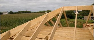
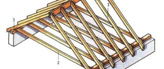
There are several ways to fasten the rafters:
Rafter mounting options
Below I will tell you in more detail about all the installation methods, and you can choose the option that suits you.
Beginners often call the timber on which the rafters rest a rafter beam. In reality, a rafter beam is a type of roof truss that is made of metal or reinforced concrete. These structures are used to cover large buildings without load-bearing walls, for example, workshops or warehouses.
Rafter beams allow you to span large buildings that do not have internal walls
Using fasteners
This method of fastening is the simplest and fastest. Its principle is based on the fact that the leg is cut from the end at an angle equal to the angle of inclination of the slope, which makes it possible to maximize the support area of the rafter leg.
In this case, special fastening elements are used to fix the leg, such as:
- Toothed plates that are clogged at the junction of parts. The plates are laid on both sides of the joint. It must be said that they can be used to connect any parts of the rafter system;
You can ensure a reliable fastening point using serrated plates
- Perforated plates. They are placed at the junction of the parts and tightened with screws or fixed with nails.
The use of fasteners can significantly simplify and speed up the process of constructing a rafter system. However, fasteners do not tolerate thrust loads well.
Therefore, the legs must be tightened with crossbars. In addition, it is additionally advisable to use racks, as in the photo below.
The fastening unit using toothed plates must be reinforced with racks
Inset
The insert allows for rigid fastening of the leg to the base. Moreover, this method can be used to install rafters both on the floors and on the mauerlat.
Floor material and design
Table for calculating the cross-section of floor beams.
In general, a floor is a load-bearing building structure, divided according to its purpose: interfloor, attic, attic. Structurally, the floor can be divided into two types: prefabricated (longitudinal beam and transverse flooring) and monolithic (slab).
In the construction of private houses, prefabricated floors using wooden beams are most widely used. This material is made from durable deciduous and coniferous wood. The size of a standard specimen, depending on the purpose of the floor and loads, ranges from:
- height 150-300 mm,
- width 100-250 mm.
To increase durability, the timber is impregnated with an antiseptic and oiled.
Reinforced load-bearing structures are sometimes made using metal beams. Standard steel beams are available for these purposes. Safety standards state that if such beams are used, their ends must rest on the brickwork through distribution pads.
Monolithic floors are made of reinforced concrete slabs. Factory slabs are used, consisting of reinforcement and concrete mass with standard dimensions. To reduce weight, the slabs are usually made hollow.
Beam sealing methods
Scheme for embedding the ends of wooden beams in the attic floor into a wall 2 bricks thick.
The reliability and safety of the ceiling are largely determined by the correct embedding of the beam into the wall. The embedment determines the nature of the support on the brick wall, and this stage of construction is the most important.
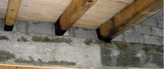
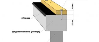
The wooden beam is installed in a niche made in brickwork, up to 150 mm deep. The end ends undergo certain processing: the end is hewn at an angle of about 60º, impregnated with antiseptic and resin, and wrapped in roofing felt or roofing felt. The wrapped ends are laid in a brick wall with a gap of 30-50 mm from the back wall of the niche. The gap is filled with thermal insulation (mineral wool, felt, etc.). The laid ends are usually coated (sealed) with a concrete solution, bitumen or covered with a layer of roofing felt.
A thick brick wall and a beam resting on it
In the case where the thickness of the brick wall exceeds 600 mm (2.5 bricks), a slightly different sealing method is recommended. The nest in the brickwork is made in such a way that there is a distance of at least 100 mm between the end of the beam and the rear wall of the niche. The total depth of the niche is selected taking into account the fact that the beam must rest on the wall at a length of at least 150 mm. The gap left allows you to place heat-insulating material in it and provide an air gap.
The lower part of the nest is reinforced with concrete mortar, a bitumen layer and two layers of roofing felt or roofing felt. In this way, a laying cushion is created, which at the same time levels the surface of the masonry. The niche in its upper and side parts is covered with roofing felt.
Supporting a beam when reducing wall thickness
Scheme for embedding the ends of a beam into a wall with a thickness of 0.64 m or more.
When performing overlapping on brick walls with a thickness of about 500 mm (2 bricks), the sealing method should be changed. A wooden box (box) with 2-3 walls is installed in a niche up to 250 mm deep, left in the brickwork. Tarred felt is placed between the back wall of the niche and the box. The walls of the box are treated with an antiseptic and impregnated with resin.
The lower part of the niche is leveled with two layers of roofing felt or roofing felt. The side walls of the nest are insulated with felt. The box is installed in a niche so that it presses the felt. The floor beam rests on the bottom of the box at a length of at least 150 mm.
With a reduced thickness of the brick wall, you should control the thickness of the wall remaining after the formation of the niche. When the wall thickness is less than 50 mm, there is a danger of cold penetration, and, therefore, it is necessary to provide additional insulation in the area where the beam rests on the brick wall.
Installation and fastening of beams
The process of installing beams in the manufacture of floors depends on the purpose of the floor, its area and loads. Typically, wooden beams are distributed along load-bearing brick walls at a distance of 600 to 1500 cm from each other. The sealing of beams begins with the outer ones and is evenly distributed along the length of the wall. It is recommended to provide a gap of at least 5 cm between the end beam and the edge of the wall.
Scheme of laying floors and subsequent fixation.
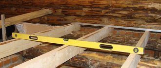
An important element of floor installation is checking that the beams are fastened horizontally and that all beams are at the same level relative to the floor. Horizontal deviation or uneven level will cause additional load in the area of support on the brick wall, especially after further laying of the transverse floor boards.
You can increase the reliability and rigidity of support on a brick wall by using additional fasteners. Steel anchors are most widely used. The anchor is strengthened so that there is a distance of at least 15 mm between the outer surface of the wall and its end. The anchor and the floor beam are fastened with nails and a metal plate measuring at least 6x50 mm.
Floor installation
After completing the installation and sealing of the beams, the transverse flooring is installed. To make the flooring, boards 25-45 mm thick and thick plywood are used. The flooring is installed on top of layers of thermal insulation. When making interfloor ceilings, a noise-insulating layer is also laid. Installation of the flooring is carried out on top of bars (joists), which are fastened across the load-bearing beams.
Sealing the ends of a wooden floor beam
- Floors
In brick houses, wooden floor beams should be placed with their ends on the walls, or inserted into nests arranged for this purpose; in wooden houses, they should be cut into the upper rims of the wall along its entire thickness.
In earthen walls, beams should be placed on the frame. There are areas in interfloor ceilings where condensation can form. It is formed, as a rule, in places where ceilings adjoin external walls. In such places, the structure may freeze and become ventilated. To avoid this, the joints between floors and external walls must have sufficient heat protection and air tightness.
Wooden floor beam, water vapor diffusion
The joint cavity of a wooden floor beam resting on a brick wall must be protected from moist air entering from the premises. This is due to the fact that water vapor contained in the warm air will be cooled by the cold outer walls and condense, moistening the ends of the beam. The ends of the beam are antiseptic to avoid rotting, and their surface is covered with roofing felt in 2 layers.
You cannot paste over the ends of floor beams.
Wooden floor beams resting on brick walls: a - one beam; b - two beams; 1 - sealing with mortar; 2 - two layers of roofing felt; 3 - anchor; 4 — antiseptic part of the beam; 5 - nail; 6 — steel plate 50×6 mm; 7 - two layers of roofing material
When resting wooden floor beams on the wall, the depth should be 12-15 cm, and the depth of the nests should be 18 cm. Such a gap is necessary so that water vapor can freely escape out through its unopened end.
The nests should be 2-3 cm larger than the cross-section of the beam. After installing the beams, the nests are sealed with mortar to protect the joint from the penetration of moist air from the premises.
Wooden floor beams are reinforced one at a time to ensure rigidity with steel anchors, the ends of which, in order to avoid temperature bridges, do not reach the outer surface by 12 cm and protrude inward by 20 cm. The anchors are attached to the wooden beams with steel plates (50×6 mm) and ø5 nails -6 mm.
Open sealing of the ends of the floor beam is permissible only if the humidity in the house is ≤ 60% and there is excellent ventilation. The wall thickness of the nest in a brick wall composed of wooden floor beams supported on brick walls is ≥ 46 cm.
Sometimes open sealing of the ends of the floor beams is performed, but this is only possible in rooms with normal humidity (no more than 60%) with good ventilation of the floor (with slotted skirting boards) and sufficient thermal insulation capacity of the rear wall of the nest. The wall thickness of the nest with a brick wall must be at least 46 cm. If the thickness is less, the nest should be insulated to ensure a heat transfer resistance of 0.57 m²⁰C/W (central Russia).
Floor beam, open ends embedded in a wall 0.51 m thick; 1 - beam; 2 - insulation; 3 - wooden board; 4 - wooden box; 5 — gasket (roofing material) in 1-2 layers
The node for supporting a wooden floor beam on a wall with a thickness of 2 bricks (0.51 m) is solved as follows. A nest 25 cm deep (1 brick) is made in the wall. Its vertical wall is insulated with felt (antiseptic or mineral). 2 layers of roofing material are laid on the lower surface of the nest. After this, an antiseptic wooden box is installed in the nest, with which mineral felt is pressed. The floor beam is supported on the lower surface of the box to a depth of 15 cm so that there is an air gap between the box and the beam. One solution is to use a box without a lower horizontal surface. In this case, the end of the beam is covered with 2-3 layers of roofing felt, laid in a nest.
Floor beam, embedding the ends into the wall with a thickness of 0.64 m or more: 1 - beam; 2 - floor; 3 - lags; 4 - end of the beam wrapped in 2 layers of roofing material; 5 - board 25 mm thick; 6 - roofing material; 7 — insulation (construction felt in 1 layer); 8 - roofing material in 1-2 layers
A wooden beam in walls 2½ bricks thick or more is supported in a nest 25 cm deep. The lower surface of the nest is covered with bitumen. After this, all surfaces are covered with roofing felt. In the nest at its rear surface, thermal insulation (mineral felt) is placed, pressed against the rear wall with a board. An air gap of 4 cm should be left between the beams and the walls.
Wooden beams and requirements for them
In principle, beam floors can also be different: reinforced concrete, metal, or wood. The first two options are not inferior in technical characteristics to slab floors, but they are quite complex to implement, and therefore are practically not used in private construction. But wooden beams are a completely different matter!
- Despite its apparent simplicity, there are also a lot of nuances that must be observed. First of all, you should choose the right lumber. Most often, hard coniferous wood is used for this purpose: larch, pine, spruce, cedar. The price doesn’t matter here - it’s just that coniferous beams work best in bending.
Pine timber for beams
- There are, of course, advocates of deciduous wood who claim that aspen and birch cope well with this task. But building codes recommend that all load-bearing wooden structures - and not just floor beams - be made from softwood lumber. Hard hardwood, suitable only for connecting parts (dowels, dowels, etc.).
- It is possible, and even preferable, to use planed timber rather than glued timber for flooring. It must be well dried and treated with a fire-retardant compound before installation. In heated buildings, solid beams must be installed without intersecting walls and partitions, and the floor structure, as such, must guarantee good ventilation.
Floor plan
- Blind (monolithic) embedding of beams into walls is not allowed - they are placed in nests, and always on shock-absorbing pads made of deciduous wood. The ends of beams mounted using metal fasteners must be protected with a moisture-proof layer, since when condensation forms, metal corrosion can lead to wood corrosion.
But before starting installation work, the load-bearing elements of the floor need to be calculated. Therefore, further you will be offered instructions for selecting the section of beams and determining the step of their installation.
| Naboka Alexander Andreevich St. Petersburg Polytechnic University of Peter the Great (St. Petersburg, Politekhnicheskaya street, 29), [email protected] |
| Key words: reinforced concrete flooring on metal beams reconstruction replacement of flooring units of the floor structure flooring on a profile sheet major repairs | Abstract: Reconstruction and major repairs of buildings have been gaining momentum in recent years. For the central regions of large Russian cities, the problem of eliminating the accident rate of building structures is very relevant. There are a number of regional programs for carrying out major repairs in multi-apartment residential buildings. The article provides design solutions and recommendations for the installation of reinforced concrete floors on metal beams in the old housing stock. |
Main text
In [1] they refer to UNESCO statistics, according to which more than 50% of all European residential buildings were built in the period before the 50s of the last century. The need to repair or reconstruct a large number of residential buildings is now beyond doubt. Thus, in St. Petersburg there is a regional program for the overhaul of common property in apartment buildings in St. Petersburg, for which it is planned to allocate about 32 billion rubles from 2021 to 2021 [2].
Carrying out such a volume of work requires the involvement of a large number of specialists in the field of design. The work contains design solutions for the installation of a new interfloor ceiling in order to facilitate, reduce labor costs and optimize the design process. It is worth noting that the design solutions given are not binding and, in the opinion of the author, are purely advisory in nature and may contain errors and inaccuracies. The application of a particular solution must comply with existing standards and be confirmed by calculations.
The building structures of the old housing stock are not only outdated - the layouts are outdated and the quality of engineering equipment does not meet modern standards, but also physically - individual structures outlive their operational period and are not able to meet the strength and reliability requirements imposed on them at the time of construction. The main causes of physical wear and tear [3] are both time, a long period of use, and operating conditions - untimely and improper care and repairs.
Defects and damage, as well as the causes of their occurrence characteristic of a particular type of structure, can be found in [4].
We are interested in overlaps. The most common types of floors in old apartment buildings are floors on metal and wooden beams. Floor structures are shown in Figures 1 and 2.
Figure 1. The most common design of interfloor ceilings on wooden beams in the old foundation
Figure 2. The most common design of interfloor ceilings on metal beams in the old foundation
When carrying out a major overhaul, it may be discovered that the existing load-bearing beams are in poor condition and require replacement. Then there is a need to install a new floor. The simplest design is a reinforced concrete floor on metal beams using a profile sheet as permanent formwork. Further solutions for the arrangement of this floor will be considered.
First of all, you need to install the metal beams. It is better to use rolled profiles as load-bearing beams. Figure 3 shows a node for supporting a metal beam on a load-bearing brick wall of a house.
Figure 3(a). Beam support unit on brickwork
Figure 3 (B). Supporting unit for a beam on brickwork. Section A-A
Figure 3 (B). Supporting unit for a beam on brickwork. Section B-B.
Where, 1 – stiffener; 2 – support sheet.
The stiffener is installed to ensure the stability of the beam and prevent bending of the I-beam flange. The support sheet is necessary to distribute the load on the brickwork.
Other design options for the support unit can be found in [5].
The span between load-bearing walls sometimes reaches 6 m or more, and it is not possible to deliver a metal beam to the mounting mark in one piece due to its large weight. Narrow entrances, the impossibility of installing lifting mechanisms and equipment for lifting beams - all these are the difficulties that builders encounter. Then it becomes necessary to make an equal-strength installation joint, shown in Figure No. 4.
Figure 4. Equal-strength assembly joint of beams.
The most popular is the assembly joint, in which the top and bottom plates are the same in width and wider than the I-beam flanges. But in construction conditions, for the convenience of welding work, the upper plate can be made narrower than the I-beam shelf, then the lower one should be enlarged. (This is exactly the joint shown in Figure 4).
All metal elements must be protected from corrosion. A typical solution is a layer of GF-021 primer and 2 layers of PF-115 enamel. Fire protection measures for metal structures should also be taken into account.
After installing the beams, they begin to install a reinforced concrete slab along the top flange of the I-beam and inter-beam filling.
The predominant way to install reinforced concrete slabs in the old foundation is to use corrugated sheets as permanent formwork. (If the designer decides to use a profiled sheet also as working external reinforcement, the requirements specified in [6] should be taken into account).
Profiled sheets should be joined together along the longitudinal edges with an overlap using self-drilling screws or rivets with a pitch of no more than 500 mm. They should be attached to load-bearing metal beams using metal screws in each corrugation on the outer supports and through the corrugation in the intermediate ones.
The profile flooring should be selected depending on the pitch of the beams so that it can withstand the load from the weight of the slab until it gains strength.
Figure 5 shows a possible floor reinforcement scheme.
Figure 5. Scheme of reinforcement of a floor slab using a profiled sheet.
The reinforcement consists of longitudinal rods laid in each corrugation of the corrugated sheet and upper reinforcing mesh with a pitch of 150-200 mm. The frame elements are connected either by welding or using steel wire.
Figure 6. Flooring on metal beams using profiled sheets as permanent formwork
The sound attenuation in a reinforced concrete floor slab is too low, so additional sound insulation is necessary to ensure comfortable living conditions and reduce noise levels. There is a wide selection of heat and sound insulating materials on the market, and depending on your budget, you can select the required material. To fix the material on the bottom shelf, use a profile sheet or separate profiles. As a finishing touch, you can use plasterboard facing panels.
At the end the overlap pie will look like shown in Figure 7
Figure 7. Final overlap pie
This overlap will allow you to implement any layout; however, the partitions should be made of lightweight materials, for example, gypsum plasterboard. Possible options for partitions can be found in [7].
It is worth noting that the installation of such an overlap may be accompanied (depending on the type of initial overlap) by an increase in loads on the walls and foundation. When replacing floors on more than just one floor, an inspection should be carried out to ensure that the walls, foundation and base are able to withstand the design loads.
Conclusion.
A sharp increase in the volume of major repairs and reconstruction work carried out in the old building indicates the need to develop standard solutions.
The article contains design solutions and recommendations for the construction of a new floor, which are widely used in rear reconstruction. All accepted materials must be certified and comply with current regulatory documents.
Bibliography
1. Savyovsky, V.V. Repair and reconstruction of civil buildings / V.V. Savyovsky, O.N. Bolotskikh. – Kharkov: Publishing House “Vaterpas” 1999. – 287 p.
2. Decree of the Government of St. Petersburg dated December 8, 2016 No. 1127 (short-term plan for the implementation of the regional program for capital repairs of common property in apartment buildings in St. Petersburg in 2021, 2021 and 2021)
3. Rabinovich G.M. Twice born / G.M. Rabinovich. - Leningrad: Stroyizdat, (Leningrad branch Leningrad, Ostrovsky Square, 6) 1971. - 112 p.
4. Fizdel, I.A. Defects and methods for their elimination in structures and structures (2nd edition, supplemented and corrected) / I.A. Fizdel. – M.: Stroyizdat. 1970. – 175 p.
5. TsNIIproektstalkonstruktsiya. Series 2.440-1 Issue 1. Frame and hinge units of beam cages and connections of crossbars to columns / TsNIIproektstalkonstruktsiya, VNIKTIstalkonstruktsiya Ministry of Montazhspetsstroy of the USSR, VNIPI Promstalkonstruktsiya - approved 12/15/1981 Gosstroy USSR (State Committee of the Council of Ministers of the USSR for Construction Affairs)
6. JSC "TSNIIPSK im. Melnikov." STO 0047-2005 Steel-reinforced concrete floors with a monolithic slab on a steel profiled flooring. Calculation and design / JSC TsNIIPSK im. Melnikov", CJSC "Hilti Distribution Ltd" - M. 2005 - 63 p.
