Kinds
To adapt to different control circuit options, RGB diodes are produced in several modifications:
- Common cathode version
- Version with common anode
- Without common anode or cathode, with six terminals
In the first case, the LED is controlled by positive polarity signals supplied to the anodes, in the second - by negative pulses supplied to the cathodes. The third modification of the design allows any switching options and is usually produced in the form of an SMD component.
Design and purpose of an RGB LED
To display the entire palette of shades, three colors are sufficient, using RGB synthesis (Red - red, Green - green, Blue - blue).
The RGB palette is used not only in graphic editors, but also in website development. By mixing colors in different proportions you can get almost any color. The advantages of RGB LEDs are their simplicity of design, small size and high light output efficiency. RGB LEDs combine three crystals of different colors in one package. RGB LED has 4 pins - one common (the anode or cathode has the longest pin) and three color pins. A resistor must be connected to each color output. In addition, the RGB LED Arduino module can be directly mounted on the board and have built-in resistors - this option is more convenient for robotics classes.
Photo. RGB LED pinout and RGB LED module for Arduino
The RGB LED pinout is shown in the photo above. Note also that many full-color (tri-color) LEDs require diffusers, otherwise the color components will be visible. Next, we will connect a three-color LED to the Arduino and make it first blink in different colors, and then smoothly shimmer in different colors using “pulse width modulation”.
Connection
As an example, we will give a diagram for connecting RGB diodes to the Arduino universal automation unit, created on the basis of the ATMEGA microcontroller. In Fig. Figure 2 shows a connection diagram for an rgb led with a common cathode.
Rice. 2
Below is a diagram with a common anode:
Rice. 3
The RGB pins in both cases are connected to the digital outputs (9, 10,12). The common cathode in Fig. 2 is connected to the minus (GND), the common anode in Fig. 3 is connected to the power supply positive (5V).
Arduino is a simple controller for beginner roboticists, which allows you to create various devices on its base, from ordinary LED color music to intelligent robots.
Control
The LED turns on when direct current passes, when the anode is connected to the plus, the cathode to the minus. A multi-color emission spectrum can be obtained by changing the intensity of the channels (RGB). The resulting hue is determined by the ratio of brightnesses of individual colors. If all 3 colors are equal in luminescence intensity, the resulting color is white.
Periodic rectangular voltage pulses are formed at the digital outputs of the Arduino board, as in Figure 4, with a variable duty cycle.
Rice. 4
For those who forgot. The duty cycle is the ratio of the duration of the pulse repetition period to the pulse duration.
The lower the duty cycle of the channel pulses, the brighter the glow of the corresponding LED diode. The program for controlling the duty cycle of color channel pulses is hardwired into the controller chip. This change in the duty cycle of pulses, carried out for the purpose of controlling the process, is called PWM (pulse width modulation).
Figure 4 shows examples of diagrams of rectangular pulses of various duty cycles.
The color and intensity of the rgb diode can be controlled without PWM. The diagram below uses analog control of three-color LEDs. Its essence is to regulate the direct current of diodes of a certain color.
Rice. 5
In the diagram (Fig. 5) rgb diodes (led1-led10) have a common anode. The cathodes of the same color of all diodes are combined, and through resistors R4.1, R4.2, R4.3 are connected to the emitter of the corresponding transistor. Thus, all red LEDs are connected to transistor VT1.1, green LEDs are connected to VT1.2, blue LEDs are connected to VT1.3. When you move the sliders of potentiometers R1.1, R1.2, R1.3, the base current of the corresponding transistor changes. The magnitude of the base current determines the degree of opening of the emitter-collector junction, and, ultimately, the brightness of the corresponding color. Before connecting, you need to correctly determine the polarity of the LED, otherwise it will not light.
The use of digital programmable controllers provides virtually limitless color control possibilities. In those cases where the creation of dynamic color images is not required, an analog control method can be used. These can be external or interior lamps for static lighting with a choice of colors.
By the way. The use of such regulation in the lighting systems of vehicle instrument panels allows the driver to choose any shade and brightness.
Device and scope of application
Structurally, RGB LEDs are three LED chips with one optical lens, located in one housing. Color control occurs by applying electrical signals to the terminals of each LED chip, and the combination of emissions from all three LEDs allows you to adjust the final color. For example, below is the most popular RGB LED SMD 5050.
An RGB LED is a full-color LED; by mixing three colors in different proportions, any color can be displayed. For example, if you light all three colors at full power, you will get a white glow.
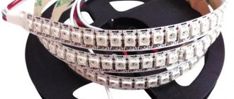
The areas of application of RGB LEDs are directly related to the development of the advertising and entertainment market. Also, ready-made RGB lamps and strips are used in the field of lighting design of architectural and design solutions - night lighting of buildings or fountains, interior lighting, car indicator systems, etc.
Table of wavelengths of smd 5050 LEDs, different luminescence
The variety of applications of multicolor LED light sources determines the main types of external design of RGB LEDs: low-power products are produced in standard round cases with a spherical lens and leads for conventional soldering; low-power RGB LEDs in surface-mount SMD packages are widely used in LED strips or large-area full-color LED screens; in Emitter-type housings they produce powerful RGB light sources with independent control of each LED crystal; super bright LEDs in housings.
To simplify light control systems, control chips are built into the housings of some series of multicolor LED light sources. Pin Layouts (Pinout) Several standard control circuits determine the structure of the external pins of RGB LEDs and their connection inside the housing. There are three main pinout patterns that are followed on most manufactured products:
- In a common cathode circuit, three independent anode terminals are used for control, and the cathode terminals of the LED crystals are interconnected;
- The pinout with a common anode is controlled by negative pulses to the cathode terminals, and the anode electrodes of the LED crystals are connected together;
- The independent connection circuit has six pins according to the number of LED crystals; no connections are made inside the housing.
It will be interesting➡ What are NTC thermistors
There is no single standard for pinout; the specific type of arrangement of external pins is used depending on the tasks assigned. If there are no documents for the LED product, the type of external pins can be easily determined using a multimeter. In the dialing mode, the LED will glow (high-power LEDs are very weak), and the multimeter will make a connection sound if the red probe of the multimeter is connected to the anode of the LED crystal, and the black one to its cathode. In the case of a reverse connection, there will simply be no visible or audible effects.
Three LEDs and their sizes
The simplest way to connect and control the operating modes of RGB LEDs is implemented using standard Arduino microcontrollers. The common pin is connected to a single bus of the microcontroller, and control signals are supplied to the terminals of LED crystals through limiting resistors. The lighting modes of LED crystals are controlled using pulse-width modulation, where the duty cycle of the pulses determines the light intensity. Programming the PWM modulator determines the final color of the entire device or the cyclic operating modes of each color.
Material on the topic: What is a time relay
RGBW LEDs
In order to obtain a pure white color using a multi-colored rgb LED, it is necessary to accurately balance the brightness of the glow across the crystal of each color. In practice this can be difficult. Therefore, to reproduce white color and increase the variety of color effects, the rgb diode was supplemented with a fourth white crystal.
Most often, RGBW LEDs are used in RGBW SMD LED strips. To power such LED strips, special RGBW controllers have been created, usually controlled by infrared remote controls.
The photo shows a powerful four-color LED module SBM-160-RGBW-H41-RF100 manufactured by Luminus Devices Ink.
Rice. 6 RGBW LED module from Luminus
Time after time we are asked where to buy an RGBW LED, so in order not to answer everyone, we decided to write about it in an article.
We buy all LED products in China through the AliExpress marketplace, only from trusted sellers with fast delivery, at the lowest prices. Follow the link and see for yourself - look at the RGBW LED on AliExpress.
How to control an LED on Arduino
The RGB strip is controlled by adjusting the range of pulse width modulation signals, which allows you to adjust the strength of the electric current. Pulse width modulation signals are encoded with numbers in the range from 0 to 255. This encoding method allows you to get 16.8 million different color shades on the Arduino RGB.
To control RGB LEDs, the following components are required:
- Arduino UNO R3, Nano or Mega controller.
- RGB diodes;
- 3 resistors with a resistance of 220 Ohms;
- wired plus-minus mechanisms.
Arduino UNO R3 controller.
When connecting an LED to Arduino, you need to connect the negative wire to the GND ground pin. The blue diode is connected to Pin13, the green to Pin 12, and the red to Pin 11.
After connecting the main components, you need to open the Arduino IDE, connect the board to your personal computer using a USB cable and upload the following sketch to the microcontroller:
| 1 2 3 4 5 6 7 8 9 10 11 12 13 14 15 16 17 18 19 20 21 22 23 24 25 26 27 28 29 30 31 32 33 34 35 | int red_light_pin= 11; int green_light_pin = 10; int blue_light_pin = 9; void setup() { pinMode(red_light_pin, OUTPUT); pinMode(green_light_pin, OUTPUT); pinMode(blue_light_pin, OUTPUT); } void loop() { RGB_color(255, 0, 0); // Red delay(1000); RGB_color(0, 255, 0); // Green delay(1000); RGB_color(0, 0, 255); // Blue delay(1000); RGB_color(255, 255, 125); // Raspberry delay(1000); RGB_color(0, 255, 255); // Cyan delay(1000); RGB_color(255, 0, 255); // Magenta delay(1000); RGB_color(255, 255, 0); // Yellow delay(1000); RGB_color(255, 255, 255); // White delay(1000); } void RGB_color(int red_light_value, int green_light_value, int blue_light_value) { analogWrite(red_light_pin, red_light_value); analogWrite(green_light_pin, green_light_value); analogWrite(blue_light_pin, blue_light_value); } |
int red_light_pin= 11;
int green_light_pin = 10; int blue_light_pin = 9; void setup() { pinMode(red_light_pin, OUTPUT); pinMode(green_light_pin, OUTPUT); pinMode(blue_light_pin, OUTPUT); } void loop() { RGB_color(255, 0, 0); // Red delay(1000); RGB_color(0, 255, 0); // Green delay(1000); RGB_color(0, 0, 255); // Blue delay(1000); RGB_color(255, 255, 125); // Raspberry delay(1000); RGB_color(0, 255, 255); // Cyan delay(1000); RGB_color(255, 0, 255); // Magenta delay(1000); RGB_color(255, 255, 0); // Yellow delay(1000); RGB_color(255, 255, 255); // White delay(1000); } void RGB_color(int red_light_value, int green_light_value, int blue_light_value) { analogWrite(red_light_pin, red_light_value); analogWrite(green_light_pin, green_light_value); analogWrite(blue_light_pin, blue_light_value); } After compiling this code, the crystals will light up in rainbow colors. To configure the gamma of a three-color LED, you need to change the values of the red, blue and green variables in the program code. To make all the diodes white, you need to set all color values to 255.
White LED.
Commands are transmitted sequentially between ports. The movement of PWM signals is indicated by arrows on the Arduino LED strip. 2 x 220 ohm resistors are required to prevent the board ports from burning out or causing a short circuit.
Before connecting the RGB LED to the Arduino, you need to measure the distance between the strip and the microcontroller. If the components are located at a long distance, then it is necessary to purchase wires at least 15 cm long. To protect the mechanisms from interference, it is recommended to twist the wired devices. This will ensure stable operation of the communication protocol.
To control the LED diode, the free GyverRGB electronic library is required. It contains frequently used commands, which simplifies the process of writing a sketch.
The GyverRGB library contains software constructs that perform the following functions:
- Setting colors and shades in HEX format.
- Pulse width modulation polarity control.
- Adjusting the brightness of the LEDs.
- Adjusting the PWM correction frequency.
- Restriction of electric current supply.
- Smooth change of colors as the battery discharges.
The GyverRGB library supports working with RGB diodes simultaneously connected to the Arduino board. It has a built-in LUT correction matrix that allows you to change the color gamut with a minimum PWM signal. The library contains over 1530 values for the ColorWheel tool.
LED diodes.
If, after setting the basic parameters of the software environment, the LED does not light up, then you need to check the availability of drivers for the Arduino board on the computer.
To do this, you need to perform the following algorithm of actions:
- Go to the device manager and find the column with the name of the Arduino microcontroller.
- Click on the “Details” tab.
- From the list that opens, select the “ID equipment” column.
- Copy the device identification number found in the text field.
After this, you need to go to the Internet and paste the copied text into the search bar. A large number of web pages with links to download files will open in the browser. It is recommended to download drivers only on the official websites of software manufacturers. Otherwise, you can download a file containing virus programs. It can lead to damage to the personal computer or loss of the user's personal data.
Application
The main area of application of rgb LEDs is the creation of lighting effects for advertising, stage design of concert venues, entertainment events, festive decoration of buildings, illumination of fountains, bridges, monuments.
Interesting results are obtained when using rgb led diodes for designer lighting design of interiors. For these purposes, the production of various lighting equipment based on rgb and rgbw diode technology has been launched, the range of which continues to expand and conquer new areas of application.
Where can I buy
As we said above, to purchase LED products, including three-color RGB LEDs, we recommend the AliExpress marketplace; recently many high-quality products and trusted sellers have appeared on it at low prices.
As usual, we have prepared for you the best products that meet the basic requirements: the lowest price, positive reviews, a large number of orders, fast delivery and a trusted seller. Let's move on to our selection:
- Buy an RGB 3528 LED from CHANZON - the most popular company on the Chinese market, characterized by good quality and low prices for its products. SMD type LED.
- Buy a surface-mount RGB LED from CHANZON; these are very often used to work with the well-known Arduino microcontroller.
- Buy a powerful RGB LED from LEDGUHON - also a well-known company, such LEDs are also called “Star” due to the fact that they are located on a printed circuit board of the appropriate shape, power 3 W, very similar to the CREE LED.
If you have any questions, use the comment form located immediately below this article and leave your question, we will definitely contact you.
What does RGB mean?
RGB is short for Red Green Blue. And, as you may have guessed, it refers to color and its composition. You may ask why red, green and blue? The answer is that red, green, and blue are primary colors that you can combine in varying amounts to make any other color in the visible spectrum that the human eye can see.
RGB is an additive color model. In other words, to make other colors, you mix the primary colors red, green and blue. If you mix all three colors at maximum intensity (100%), you will get white. On the other hand, if you mix them all at the lowest intensity (0%), you will get black.
RGB color model
In other words, if you mix 100% brightness of red, green and blue you will get light, but if you mix 0% red, green and blue you will get darkness.
RGB can also be considered the opposite of CMY, which stands for "Cyan Magenta Yellow". Why the other way around? Because CMY, as a color model, is the opposite of RGB: combining cyan, magenta and yellow at a maximum intensity of 100% gives you black, and a minimum intensity of 0% gives you white.
CMY color model
Read: What is quality of light?


