What is addressable LED strip
Addressable LED strip is a long color RGB LED strip based on a flexible printed circuit board, on which RGB LEDs with limiting resistors, capacitors and control controllers are placed on one side. An addressable LED strip differs from a regular RGB LED strip in that all the LEDs on it are connected in parallel and each of them is separately controlled by its own controller.
As with any LED strip, an addressable LED strip requires a stabilized power source with a high output current.
The difference between a regular RGB strip and an addressable LED strip
The color of a conventional colored LED strip is set to be the same along its entire length by one external controller, and thus you can set almost any color or shade. In an addressable LED strip, each LED installed on the strip can be controlled separately by its own PWM regulator and controller. It turns out that it will be possible to set different colors for all the LEDs on the strip.
Very often, RGB-controlled LEDs in an addressable LED strip are connected to a 5 V power source, in which case all the LEDs on such an addressable LED strip are connected in parallel. The latest modern versions of such strips began to use a connection of three LEDs per section in series, which made it possible to connect them to a 12 V power source.
Unlike a regular RGB color LED strip, addressable LED strips will not work without control commands coming from an external control processor. Even if they are connected to a power source, not a single LED will light up until the corresponding turn-on command is received.
Addressable LED strips have a beginning and an end, which must be taken into account when connecting. For convenience, many tapes have arrows indicating the direction from beginning to end.
Where is addressable LED strip used?
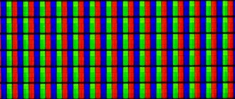
The range of applications for addressable LED strips is as wide as that of conventional RGB strips. They are used for decorative lighting of various objects, car interiors, for interior decoration, and are especially actively used in the design of advertising signs. Thanks to the ability to control each LED individually using addressable LED strips, you can create entire strips to display text or even huge panels to fully display color images.
Most street television panels for displaying video advertising are assembled based on addressable LED strips.
What types of addressable LED strips are there?
WS2811 and WS2812B chips can be used to control the LEDs of addressable LED strips. The WS2811 chip is manufactured in a DIP-8 or SOP-8 package and is mounted directly on the LED strip. If the LED strip is designed for a voltage of 5V, then such an integrated circuit is installed next to each RGB LED. When using 12V power, such a chip is installed one per three LEDs.
The more modern WS2812B chip is so small that it is placed directly in the RGB LED housing. Such LEDs are placed much more densely on the strip and a 5 V source is used for power supply.
In addressable (pixel) LED strips, the LEDs are connected in parallel when powered by 5V, but data is transferred from driver to driver in series. There is one big inconvenience in this: if one of the PWM regulators fails, all the LEDs following it will stop working. To solve this problem, the next series of WS2813 chips was released, which allow the use of a fourth redundant track for data transmission. With WS2813 chips, all working LEDs will work, even if some in the circuit fail.
Specifications
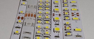
The addressable LED strip consists of RGB LEDs in a 5050 SMD package and PWM driver microchips. Currently, the most popular are addressable LED strips using WS2811 and WS2812B chips. The WS2811 modification is an integrated circuit (IC) in a DIP-8 (9.2x6.4 mm) or SOP-8 (5.1x4.0 mm) package. This 3-channel driver has the following pin configuration:
- 1 – PWM-regulated output (red);
- 2 – PWM-regulated output (green);
- 3 – PWM-regulated output (blue);
- 4 – general;
- 5 – data transmission output;
- 6 – data input;
- 7 – selection of operating mode;
- 8 – +5V power supply.
In an address strip using the WS2811 chip and a 5-volt power supply, the driver chip is located in close proximity to each SMD 5050 RGB LED, next to which there are also current-limiting resistors and a capacitor that protects against interference. But today such models are outdated and extremely rare. Today, addressable LED strips on WS2811 chips are available for sale only with power supply from +12 V. In this case, the WS2811 chip controls not one LED, but a group of 3 pieces.
No sooner had the WS2811 IC gained popularity than the more advanced WS2812B took its place. This type of PWM driver is much more compact and is placed directly in the SMD 5050 LED housing. If you look closely, under the transparent phosphor you can see a miniature black rectangle with outgoing gold-plated conductors.
This unification has made it possible to significantly simplify the assembly of addressable LED strips and modules, and the WS2812B itself has only 4 pins:
- 1 – power supply (+3.5… +5.3 V);
- 2 – data transmission output;
- 3 – general;
- 4 – data input.
The driver IC consumes no more than 1 µA, and the maximum current of one addressable LED is 60 mA. Operating temperature range: from -25 to +80°C.
When choosing an addressable LED strip, an important criterion is the degree of protection from moisture and dust. For outdoor use, only models with IP65 and IP67 are suitable.
How to connect addressable LED strip
To connect a modern addressable LED strip, three contacts are required, two of which relate to power, the third is control. The power contacts, labeled GND, +5V or +12V depending on the modification, are connected to the power source. The third DIN pin is designed to transmit control data (digital input) to controllers; it is connected to the control controller, which is very often an Arduino. To transmit data, the GND pins of the addressable LED strip and the control controller must be connected.
PWM drivers can mistake any interference in the power circuit for a control signal, and so that during operation nothing interferes with the correct flow of the signal through the control channel, high-capacity electrolytic capacitors are installed in the power circuit of the LED strip and Arduino. For example, if everything is powered by a voltage of 5V, then you need to install a 6.3V 1000 µF capacitor on the power circuit of the LED strip, and 6.3V 470 µF on the Arduino power circuit. The DIN pin connects to the Arduino through a resistance of 200 ohms to 500 ohms.
The PWM drivers installed on the addressable LED strip are 8-bit, which means that 256 different gradations of brightness can be set for each color. For one three-color LED, for control, you will need to transfer 3 bytes of information to the driver, which will allow you to get 16.5 million shades.
Controlling the operation of addressable LED strip
An addressable LED strip with a simple power connection will not react in any way to the appearance of power. To turn it on, it requires a control code to be sent to the DIN contact. It is quite possible that accidental or intentional hand touching of this contact can lead to interference, which will be perceived by the driver as a signal and one of the LEDs will begin to glow.
When connected correctly, the control input of the LED strip receives a digital signal of 3 bytes for each LED. 1 bit of information is transmitted in 1.25 μs, the entire data packet for one LED will be transmitted in 30 μs. The first PWM driver takes the first packet of 3 bytes that arrives and transmits the next data further. After sending the first packet, a pause of 50 μs is made, which makes it clear to the next driver that it needs to receive data. This is how data is transferred to all subsequent LEDs until the pause exceeds 50 μs. A longer pause will indicate that the cycle will repeat again with new data being sent.
When using Arduino, it is proposed to use ready-made libraries, with which it is easiest to write programs for controlling addressable LED strips. These include FastLED and Adafruit NeoPixel.
How to connect an address strip to Arduino
For this lesson we will need the following details:
- Arduino Uno / Arduino Nano / Arduino Mega board;
- WS2812B tape;
- bread board;
- 1 resistor from 100 to 500 Ohm;
- male-male wires.
WS2812B LEDs are quite energy-intensive; one LED consumes up to 60 mA at maximum brightness. A strip with 100 diodes will require a power supply of 6 Amps or more. The Arduino microcontroller and the LED strip can be connected to different power sources, but the ground must be common. The fact is that the GND pin is also involved in controlling the address strip from the Arduino Uno board.
Connection diagram for 5 Volt address tape to Arduino
| WS2812B | Arduino Uno | Arduino Nano | Arduino Mega |
| GND | GND | GND | GND |
| 5V | 5V | 5V | 5V |
| DO | 10 | 10 | 10 |
Three popular libraries are used to work with tape - FastLED, AdafruitNeoPixel and LightWS2812. All libraries are available for download on our website here. Working with the FastLED and Adafruit NeoPixel libraries is easy; they differ in functionality and memory footprint. After building this simple circuit and installing the libraries, download the addressable LED strip sketch.
Sketch. Testing the WS2812 address tape
#include // connect the library #define PIN 10 // specify the pin for connecting the strip #define NUMPIXELS 3 // specify the number of LEDs in the strip // create a strip object with the required characteristics Adafruit_NeoPixel strip (NUMPIXELS, PIN, NEO_GRB + NEO_KHZ800); void setup() { strip.begin(); // initialize the tape strip.setBrightness(50); // specify the brightness of the LEDs (maximum 255) } void loop() { strip.setPixelColor(0, strip.Color(255, 0, 0)); // turn on red color on 1 LED strip.show(); // send a signal to the tape delay(500); strip.clear(); // turn off all LEDs strip.setPixelColor(1, strip.Color(0, 0, 255)); // turn on blue color on LED 2 strip.show(); // send a signal to the tape delay(500); strip.clear(); // turn off all LEDs strip.setPixelColor(2, strip.Color(255, 255, 255)); // turn on white color on LED 3 strip.show(); // send a signal to the tape delay(500); strip.clear(); // turn off all LEDs }
Explanations for the code:
- The numbering of LEDs in the strip starts from zero, so if we want to turn on the first LED, then we must indicate “0”.
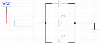
Connection diagram for a 12 Volt address tape to Arduino
If you have a 12 Volt tape, then you need to connect it according to the diagram posted above. The resistor on the digital pin protects it from burnout (if the power to the tape is turned off, it will start to be powered by the digital pin, and the pin may burn out. Also, do not connect the tape’s power to the Arduino board, otherwise the protective diode on the Arduino or USB port may burn out on the computer (in the worst case).
Sketch. Arduino address strip control
#include // connect the library #define PIN 10 // specify the pin for connecting the strip #define NUMPIXELS 3 // specify the number of LEDs in the strip // create a strip object with the required characteristics Adafruit_NeoPixel strip (NUMPIXELS, PIN, NEO_GRB + NEO_KHZ800); void setup() { strip.begin(); // initialize the tape strip.setBrightness(50); // specify the brightness of the LEDs (maximum 255) } void loop() { // turn on the red color one by one for (int i = -1; i < NUMPIXELS; i++) { strip.setPixelColor(i, strip.Color(255, 0, 0)); strip.show(); delay(100); } // turn on the green color one by one for (int i = -1; i < NUMPIXELS; i++) { strip.setPixelColor(i, strip.Color(0, 255, 0)); strip.show(); delay(100); } // turn on the blue color one by one for (int i = -1; i < NUMPIXELS; i++) { strip.setPixelColor(i, strip.Color(0, 0, 255)); strip.show(); delay(100); } }
Explanations for the code:
- Using the Adafruit NeoPixel library, it's quite easy to manage the address strip. In the examples for the library you can find many different effects. We demonstrated a simple option using a for loop to turn on the feed.
Conclusion . In this review, we only looked at the connection and the ability to control the address strip from Arduino. Since the possibilities of working with FastLED libraries, AdafruitNeoPixel are quite diverse. More interesting examples on Arduino and WS2812B are posted in the Arduino Projects section, where projects with a ticker on the address tape and other lighting effects are presented.
Addressable LED strip power
The power of an addressable color LED strip depends on the density of the LEDs on the strip and the length of the strip. The drivers that control the LEDs consume so little that they can be ignored in the calculations.
Each color LED on the strip consumes about 60 mA on average, which is approximately 20 mA per color. Knowing the number of LEDs placed on one meter of strip, you can easily calculate the total power of the connected strip.
In a 5V LED strip, all LEDs are connected in parallel. If we take as an example one meter of addressable LED strip with a density of 60 LEDs per meter, then the total current consumption of such a strip will be 3.6A. This must be taken into account when choosing a power supply.
Protocol
Now that we have figured out how to connect our tape to the Arduino, we need to understand how to control it; for this, the datasheet contains a description of the protocol, which we will now consider. Each WS2812B LED has one input (DIN) and one output (DO). The output of each LED is connected to the input of the next one. Signals must be sent to the input of the very first LED, so it will start the circuit, and data will flow from the first to the second, from the second to the third, etc. Commands to the LEDs are transmitted in batches of 24 bits (3 bytes, one byte for each color, the byte for green is transmitted first, then for red, and ends with the byte for blue LED.
LED strip sign.
Bit order is from most significant to least significant). Before each burst there is a pause of 50 μs. A pause of more than 100 μs is perceived as the end of the transmission. All bits, whether 0 or 1, have a fixed time of 1.25 µs. Bit 1 is encoded with a 0.8 µs pulse, followed by a 0.45 µs pause. Bit 0 is encoded with a pulse of 0.4 µs, followed by a pause of 0.85 µs. Actually, a visual diagram is in the photo below. Small errors of 0-150 ns per edge are also allowed. Well, it should be taken into account that this must be repeated for each LED on the strip, after which a pause of at least 100 μs must be made. Then you can repeat the transfer.
Looking at all these numbers, it becomes clear that doing all this using standard functions digitalWrite, delay and the like is simply impossible, due to their long operation and inaccuracy. Such a protocol can only be implemented by using special libraries like CyberLib or writing your own in pure C or, even worse for the current programmer, in Assembly. But not everything is as bad as it seems. WS2812B LEDs are quite popular in the Arduino community, which means that we don’t have to go into such complications, and just choose one of the solutions you like.
It will be interesting➡ What is a Zener Diode
Advantages and disadvantages of addressable LED strips
The main advantages and disadvantages of addressable LED strips are the same as those of conventional LED strips. But there are some features that set them apart.
Advantages of pixel LED strips: many options for use; high brightness and low power consumption; possibility of rendering any color; the ability to control each LED individually.
Disadvantages of pixel LED strips: inability to use at low temperatures, driver malfunctions occur;
it is impossible to turn on the LED strip without control signals; Requires powerful power supplies.