Calculation of a resistor for one LED
To power one LED, we need a power source, for example two AA batteries of 1.5V each. Let's take a red LED, where the forward voltage drop at an operating current of 0.02 A (20 mA) is equal to -2 V. For conventional LEDs, the maximum permissible current is 0.02 A. The LED connection diagram is shown in Fig. 1.
Why do I use the term "forward voltage drop" and not supply voltage. But the fact is that LEDs do not have a supply voltage parameter as such. Instead, the voltage drop characteristic of the LED is used, which means the amount of voltage the LED outputs when the rated current passes through it. The voltage value indicated on the packaging reflects the voltage drop. Knowing this value, you can determine the voltage remaining on the LED. This is the value we need to use in our calculations.
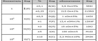
The forward voltage drop for various LEDs depending on the wavelength is presented in Table 1.
Table 1 - LED characteristics
| Color characteristic | Wavelength, nM | Voltage, V |
| Infrared | from 760 | up to 1.9 |
| Reds | 610 — 760 | from 1.6 to 2.03 |
| Orange | 590 — 610 | from 2.03 to 2.1 |
| Yellow | 570 — 590 | from 2.1 to 2.2 |
| Greens | 500 — 570 | from 2.2 to 3.5 |
| Blue | 450 — 500 | from 2.5 to 3.7 |
| Purple | 400 — 450 | 2.8 to 4 |
| Ultraviolet | up to 400 | from 3.1 to 4.4 |
| White | wide range | from 3 to 3.7 |
The exact value of the LED voltage drop can be found on the packaging for this LED or in the reference literature.
The resistance of the resistor is determined by the formula:
R = (Un.p – Ud)/Id = (3V-2V)/0.02A = 50 Ohm.
- Un.p – supply voltage, V;
- Ud — forward voltage drop across the LED, V;
- Id – operating current of the LED, A.
Since there is no such resistance in the standard series, we select the nearest resistance from the nominal series E24 upward - 51 Ohms.
To guarantee long-term operation of the LED and to eliminate errors in calculations, I recommend using not the maximum permissible current - 20 mA, but a little less - 15 mA.
This reduction in current will not in any way affect the brightness of the LED for the human eye. In order for us to notice a change in the brightness of the LED, for example, by 2 times, we need to reduce the current by 5 times (according to the Weber-Fechner law).
As a result, we get the calculated resistance of the current-limiting resistor: R = 50 Ohms and power dissipation P = 0.02 W (20 mW).
Features of connecting diodes
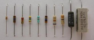
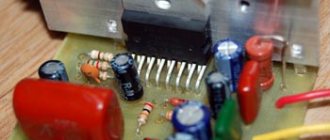
In all cases, resistors are needed to connect the elements. They often become an individual pair for each diode. The BDR-M1 block for diodes is offered at https://amtorg.com.ru/blok-dioda-i-rezistora-bdr-m1 in the railway automation section. Resistors (from resist - resistance) are necessary to adjust the voltage.
The diodes themselves are subject to fluctuations in the network. Without additional protection, they wear out faster. Diode failure, depending on its type, can have serious consequences. So, resistors can affect the operation of the TV screen. If there are problems with them, there is a risk of LED failure, which leads to the disappearance of the backlight. As a result, the image disappears. When buying a TV or other finished equipment, a person hardly thinks about the characteristics of resistors. But when independently assembling circuits with diodes of any type, you have to independently calculate these parameters. There are standards for determining the required quantities.
Calculation of a resistor for series connection of LEDs
In the case of calculating a resistor for a series connection, all LEDs must be of the same type. The LED connection diagram for a serial connection is shown in Fig. 2.
For example, we want to connect to a 9 V power supply, three green LEDs, each 2.4 V, operating current - 20 mA.
The resistance of the resistor is determined by the formula:
R = (Un.p – Ud1 + Ud2 + Ud3)/Id = (9V - 2.4V +2.4V +2.4V)/0.02A = 90 Ohm.
- Un.p – supply voltage, V;
- Uд1…Uд3 — forward voltage drop across the LEDs, V;
- Id – operating current of the LED, A.
We select the nearest resistance from the nominal series E24 upward - 91 Ohms.
Calculating an LED Resistor Using Ohm's Law
Ohm's law states that the resistance of a resistor is R = V / I, where V = voltage through the resistor (V = S – VL in this case), I = current through the resistor. So R = (VS – VL) / I. If you want to connect several LEDs at once, this can be done in series. This reduces energy consumption and allows you to connect a large number of diodes at the same time, for example, as some kind of garland.
Calculation example: Red, yellow and green diodes - when connected in series, a supply voltage of at least 8V is required, so a 9-volt battery will be an almost ideal source. VL = 2V 2V 2V = 6V (three diodes, their voltages are summed). If the supply voltage VS is 9 V and the diode current = 0.015A, Resistor R = (VS – VL) / I = (9 – 6) /0.015 = 200 Ohm. We take a 220 Ohm resistor (the nearest standard value, which is larger).
Calculation of resistors for parallel-series connection of LEDs
Often in practice we need to connect a large number of LEDs, several dozen, to a power source. If all the LEDs are connected in series through one resistor, then in this case the voltage at the power source will not be enough for us. The solution to this problem is a parallel-series connection of LEDs, as shown in Fig. 3.
Based on the power supply voltage, the maximum number of LEDs that can be connected in series is determined.
For example, we have a 12 V power supply, based on the voltage of the power supply, the maximum number of LEDs for one circuit will be equal to: 10V/2V = 5 pcs, taking into account that the voltage drop across the LED (red) is 2 V.
Why we took 10 V and not 12 V is due to the fact that there will also be a voltage drop across the resistor and we must leave somewhere around 2 V.
The resistor resistance for one circuit, based on the operating current of the LEDs, is determined by the formula:
R = (Un.p – Ud1 + Ud2 + Ud3+ Ud4+ Ud5)/Id = (12V - 2V + 2V + 2V + 2V + 2V)/0.02A = 100 Ohm.
We select the nearest resistance from the nominal range E24 upward - 110 Ohms.
The number of such chains of five LEDs connected in parallel is practically unlimited!
Calculation of a resistor when connecting LEDs in parallel
This connection is not desirable and I do not recommend using it in practice. This is due to the fact that each LED has a technological voltage drop, and even if all the LEDs are from the same package, this is not a guarantee that their voltage drop will be the same due to the production technology.
As a result, one LED will have more current than the others and if it exceeds the maximum permissible current, it will fail. The next LED will burn out faster, since the remaining current will already pass through it, distributed among other LEDs, and so on until all the LEDs fail.
When should you connect an LED through a resistor?
There are several cases where such an electrical circuit is appropriate. First, a current-limiting resistor is worth using if circuit efficiency is not a primary concern. An example is the use of LEDs as indicators in devices. In this case, the glow itself is important, not its brightness.
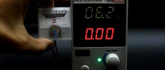
Secondly, the use of a resistor is justified in cases where it is necessary to determine the polarity and performance of the LED element. One method is to connect the device to a power supply. In this capacity, batteries from mobile phones or batteries are often used. The voltage on them can reach 12 V. This is a very high value, and connecting the LED directly will cause damage. To limit the voltage, a resistor is inserted into the circuit.
Thirdly, the resistor is used for research purposes to study the operation of new LED samples.
In other cases, you can use a driver - a device that stabilizes the current.
Calculation of resistance for an LED
With a large number of connected LEDs, especially if they are connected both in series and in parallel, manually calculating the resistance of each resistor can be problematic. The easiest way in this case is to use one of the many programs for calculating resistance.
It includes a small database of the most common LEDs, so you don't have to manually enter the voltage and current drop values, just enter the supply voltage and select the desired light-emitting diode from the list. The program will calculate the resistance and power of resistors, and also draw a connection diagram or circuit diagram.
The diode has low internal resistance. If you connect it directly to the power supply, the element will burn out. To prevent this from happening, the LED is connected to the circuit through a current-limiting resistor. The calculation is made according to Ohm's law: R=(U-Uled)/I, where R is the resistance of the current-limiting resistor, U is the power supply; Uled is the nameplate voltage value for the LED, I is the current strength. Based on the obtained value, the power of the resistor is selected.
It is important to calculate the voltage correctly. It depends on the connection diagram of the elements.
You don't have to calculate the resistance if you use a powerful variable or tuning resistor in the circuit. Current limiting resistors come in different accuracy classes. There are products for 10%, 5% and 1% - this means that the error varies within the specified range.
When choosing a current-limiting resistor, you need to pay attention to its power. almost always, if with little heat dissipation the device will overheat and fail. This will lead to a break in the electrical circuit.
When to use a current limiting resistor:
- when the issue of circuit efficiency is not the main one - for example, indication;
- laboratory research.
In other cases, it is better to connect LEDs through a stabilizer - driver, which is especially true in LED lamps.
Mathematical calculation.
To select resistance, you will have to remember your school physics course.
The figure shows a simple series electrical circuit connecting a resistor and a diode. The following designations are used in the diagram:
- U – input voltage of the power supply;
- R – resistor with voltage drop UR;
- LED – LED with voltage drop ULED (nameplate value) and differential resistance RLED;
Since the elements are connected in series, the current strength I in them is the same.
According to Kirchhoff's second law:
At the same time we use Ohm's law:
Substitute formula (2) into formula (1) and get:
Using simple mathematical transformations from formulas (1) and (3), we find the desired resistance of the resistor R:
For a more accurate selection, you can calculate the power dissipation of resistor R.
Let's take the power supply voltage U = 10 V.
Diode characteristics: ULED = 2V, I = 40 mA = 0.04A.
Let's substitute the necessary numbers into formula (4), we get: R = (10 – 2) / 0.04 = 200 (Ohm).
Dissipation power (5): will be P = (10 – 2) * 0.04 = 0.32 (W).
Installation of decoy resistors for LED lamps
When installing LED lamps in a car, some owners encounter problems with frequent blinking turn signals and on-board computer errors. How to solve them.
When installing LED lamps in a car, some owners encounter problems.
First: when installing LED lamps in turn signals, the turn signal relay operates more often, as if some lamp had burned out. This happens because the turn relays are designed for standard halogen lamps, the power of which can be in the range from 1W to 21W. LED lamps consume from 0.1 W to 6W.
The way out of this situation is to install additional resistors (decoys) or special turn relays designed for the use of LED lamps .
Since special relays are quite expensive and can only be used with LED lamps (for example, you cannot install 2 LED lamps and 2 halogen lamps), we will consider the option of connecting resistors (decoys) .
For an example of calculation, let's take a standard car that has 2 turn signal lamps in the headlights, 2 turn signal lamps on the wings and 2 turn signal lamps in the rear lights. Next, we need to determine the type of lamp: usually 21W lamps are used in headlights and lanterns, and 5W lamps are used in repeaters on the wings or mirrors.
And so, we have 4*21W+2*5W. Rated relay power 94W. At this power, the relay turns on the turn signals once every 0.5 seconds. When replacing only the front lamps and lamps in the repeaters with LED ones , the total power of the lamps is 2*3W+2*1W+2*21W = 50W. With this power, the relay will operate every 0.27 seconds, or almost 2 times more often. At the moment there are resistors with a power of 25W and 50W. It is necessary to top up the circuit to approximately 94W. At the same time, do not forget that resistors must be installed on both the left and right sides. 25W resistors were selected After connecting the resistors to the circuit, we calculate the total power: 2*3W+2*1W+2*21W +2*25W = 100W. At this power, the relay will operate once every 0.52 seconds, which practically coincides with the original time. It is very difficult to tell the difference by eye.
The second problem is a problem with the on-board computer. Many modern cars have a lamp fault detection system, which signals that a lamp has failed. In other, more advanced systems, the power supply to the damaged network is turned off and (or) its functionality is switched to other lamps (for example, burnt-out brake lights will light up in the fog lamps of the taillight). When replacing lamps with LED ones , these systems signal that the lamp has burned out. This happens because LED lamps consume much less energy than halogen lamps (for which this system is designed). For example, instead of a 55W fog light there is only 7.5W. The way out of the situation is the same resistors (falsehoods) . Installing a resistor with a power of 55W to the 7.5W available in the LED lamp will give a total of 62.5W, which does not go beyond the errors of such control systems (their error
20-30% of face value).
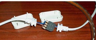
Installation of resistors (decoys) in the circuit is carried out using connectors that are included in the delivery kit. They do not damage the wires (during installation, a small cut in the wire insulation occurs, which ensures electrical contact with the conductor). When dismantling, traces of their installation are invisible. Schematic diagram of the installation of faux resistors : From the power source through a switch (or relay), current is supplied to the lamp through 2 wires “+” and “–”. The resistor is connected to the circuit in parallel. That is, one of the resistor wires, via a connector, is connected to the positive wire, the second resistor wire is connected to the negative wire. As a result, a stable system is obtained that meets factory specifications.
Next, we will consider in detail the resistor, its mounting and connection. The following figure shows 2 resistors with a power of 25 and 50 watts. Overall dimensions of the decoy resistors are 30*27*15mm and 30*50*15mm, respectively:
The kit includes a resistor, as well as 2 clamp-connectors for wires:
The resistor is connected as follows: a wire from the turn signal lamp and one of the wires from the resistor are inserted into the connector. After which, the latch snaps into place. The second wire from the turn signal is also clamped to the second wire of the resistor. In this case, the metal connector closes the wires. After closing the latch, the metal connector becomes hidden, and the body is “slammed” with the same latch:
Why should an LED be connected through a resistor?
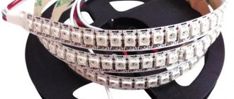
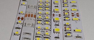
There are resistors on LED strips, there are resistors on printed circuit boards (where LEDs serve as indicators), even LED lamps have resistors.
What's the matter? Why is an LED usually connected through a resistor? Why does an LED need a resistor? In fact, everything is very simple: an LED needs a very small constant voltage to operate, and if you apply more, the LED will burn out. Even if you apply a little more, 0.2 volts more than the nominal value, the life of the LED will begin to rapidly decrease, and very soon the life of this semiconductor light source will end in tears.
For example, a red LED needs exactly 2.0 volts for normal operation, while its current consumption is 20 milliamps. And if you apply 2.2 volts, a breakdown of the pn junction will occur. For different LED manufacturers, depending on the semiconductors used and the technology for creating LEDs, the operating voltage may differ slightly in one direction or another. However, take an example of the current-voltage characteristic of a red SMD LED from one well-known manufacturer:
Here you can see that already at 1.9 volts the LED begins to glow faintly, and when exactly 2 volts are applied to its terminals, the glow will turn out to be quite bright, this is its nominal mode. If you now increase the voltage to 2.1 volts, the LED will begin to overheat and rapidly lose its resource. And if more than 2.1 volts are supplied, the LED will burn out.
Now let's remember Ohm's Law for a section of a circuit: the current strength in a section of a circuit is directly proportional to the voltage at the ends of this section, and inversely proportional to its resistance:
Therefore, if our current through the LED is 20 mA with a voltage at its terminals of 2.0 V, then what resistance does the LED have in operating condition, based on this law? Correct: 2.0/0.020 = 100 ohms. An LED in working condition is equivalent in its characteristics to a resistor with a nominal value of 100 Ohms, with a power of 2 * 0.020 = 40 mW.
But what if there is only 5 volts or 12 volts available on the board? How to power an LED with such a high voltage without it burning out? So developers everywhere decided that it was most convenient to use an additional resistor.
Why resistor? Because this is the most profitable, most economical, least costly in terms of resources and power dissipation, way to solve the problem of limiting current through an LED.
So, if there are 5 volts available, and you need to get 2 volts from a 100 Ohm “resistor”, then you need to divide these 5 volts between our useful 100 Ohm glowing resistor (which is represented by THIS LED), and another resistor whose value Now we have to calculate based on what is available:
In this circuit, the current is constant, not alternating, the elements are all linear in steady state, therefore the current throughout the entire circuit will be the same value, in our example 20 mA - this is what the LED needs. Therefore, we will choose resistor R1 of such a value that the current through it would also be 20 mA, and the voltage across it would be exactly 3 volts, which need to be put somewhere. So: according to Ohm's law I=U/R, hence R=U/I = 3/0.02 = 150 Ohm. What about power? P=U^2/R = 9/150 = 60 mW. A 0.125 W resistor is suitable so that it does not get too hot. Now it’s clear to everyone what a resistor is for an LED.
Is there a tape with SMD without resistors in nature?
Is there a tape with SMD without resistors in nature?
iurii » Jun 26, 2015, 03:03
Re: Is there an SMD tape without resistors in nature?
ivdor » Jun 26, 2015 04:23 am
It is neither something as nor any what. And as far as it’s concerned, it’s unconditional. It wouldn’t be necessary, but if such a thing were to happen, here I am for you. I'm done.
PS: Use the above information at your own risk.
Re: Is there an SMD tape without resistors in nature?
iurii » Jun 26, 2015, 12:35 pm
Re: Is there an SMD tape without resistors in nature?
ivdor » Jun 26, 2015 12:39 pm
It is neither something as nor any what. And as far as it’s concerned, it’s unconditional. It wouldn’t be necessary, but if such a thing were to happen, here I am for you. I'm done.
PS: Use the above information at your own risk.
Re: Is there an SMD tape without resistors in nature?
iurii » Jun 26, 2015 12:55 pm
Re: Is there an SMD tape without resistors in nature?
Svetoch » June 26, 2015, 13:03
Weren't you the one who wrote? There is a tape simply with series-soldered leads of 0.5 watts or less (without resistors) for connection to the driver. Cut the required amount and then either one piece or in parallel if the driver is for a higher current. I think it would be very convenient to work with one like this for gluing on aluminum slats
Where is the silicone shell?
Re: Is there an SMD tape without resistors in nature?
ivdor » Jun 26, 2015 1:09 pm
It is neither something as nor any what. And as far as it’s concerned, it’s unconditional. It wouldn’t be necessary, but if such a thing were to happen, here I am for you. I'm done.
PS: Use the above information at your own risk.
Re: Is there an SMD tape without resistors in nature?
iurii » Jun 26, 2015 1:23 pm
Where is there just ice one after another without resistors https://www.transistor.ru/catalog/ledribbon/614/ And why should such a tape be specific? Is there really no rationale for using something like this?
Re: Is there an SMD tape without resistors in nature?
Invisible_Light » June 26, 2015, 08:27 pm
Re: Is there an SMD tape without resistors in nature?
Sergey106 » 07 Jul 2015, 14:51
Re: Is there an SMD tape without resistors in nature?
» 08 Jul 2015, 00:41
Re: Is there an SMD tape without resistors in nature?
ivdor » July 08, 2015, 00:49
It is neither something as nor any what. And as far as it’s concerned, it’s unconditional. It wouldn’t be necessary, but if such a thing were to happen, here I am for you. I'm done.
PS: Use the above information at your own risk.
Re: Is there an SMD tape without resistors in nature?
» 08 Jul 2015, 02:19
Re: Is there an SMD tape without resistors in nature?
ivdor » 08 Jul 2015, 03:21
So the driver generally doesn’t care what is connected to it - be it a standard tape or load resistors. Its task is to provide current. It’s just that when you connect a tape designed for 12V, roughly speaking, a quarter of the power will go into heating the resistors. By replacing them with jumpers or 1.Ohm resistors, we reduce unnecessary losses. We get a slight difference in the calculations of the required feeder and belt.
I didn't come across any tapes with pure series resistors. Only 0.5m of “ribbon”. But for a fee, it seems to me, they can quite easily solder it into a long strip - demand creates supply.
It is neither something as nor any what. And as far as it’s concerned, it’s unconditional. It wouldn’t be necessary, but if such a thing were to happen, here I am for you. I'm done.
PS: Use the above information at your own risk.
Re: Is there an SMD tape without resistors in nature?
GafferZV » Jul 09, 2015, 08:46 pm