Do-it-yourself dial voltmeter for any voltage
Greetings, Samodelkins!
Analogue measuring instruments are gradually being replaced by digital ones, but despite this, pointer heads are still quite widespread, and not only do-it-yourselfers use them in their home-made designs. Of course, such devices are not famous for their extremely high accuracy, but nevertheless, in some measurements an analog device is simply irreplaceable.
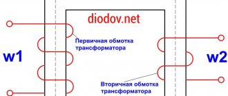
In this article we will take a detailed look at the manufacturing technology of a pointer voltmeter for a wide variety of tasks, for literally any voltage. Such a voltmeter can be used as a voltage meter in chargers, regulated power supplies, and so on. The author of this project is “AKA KASYAN” (YouTube channel “AKA KASYAN”). I think everyone knows how to measure voltage. To begin with, we naturally need an electromagnetic measuring head.
You can make such a head yourself, but this process is not so simple, so an easier option would be to find a ready-made one. Literally any dial indicator of any size is suitable for this homemade product.
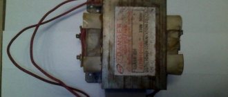
It is also desirable that the indicator have a linear measuring scale. In this example, the author used the head of a high-voltage AC voltmeter, which was safely removed from the stabilizer.
In this case, the author set the task of making a low-voltage DC voltmeter with a scale of 15-20 volts from a high-voltage alternating voltage voltmeter. As you understand, this sample is designed for operation in alternating voltage circuits, and the scale is 300V.
The first step is to open and disassemble the electromagnetic measuring head.
Inside we can see a rectifying diode and a current-limiting resistor.
The voltage from the voltmeter terminals is supplied to the winding of the measuring head through this chain of diode and resistor. We will get rid of them a little later, but now we carefully remove the scale; it is attached with double-sided tape.
After this, the scale must be scanned.
Next, the resulting drawing needs to be edited. Any editor is suitable for this purpose; even the well-known “Paint” can cope with this task without much difficulty. We remove all defects, draw incomplete lines, symbols and inscriptions, and of course change the numbers to the required ones.
In this case, it was decided to make the scale at 16V.
Then we take a ruler and measure the dimensions of the native scale.
After that, open Word, insert our drawing there, indicate the resulting dimensions, and of course, print out the whole thing, it’s better to have several pieces at once, you never know.
Then we glue it in place with any available glue.
So, we seem to have sorted this out, now we carefully bite off the chain of resistor and diode, which was mentioned at the beginning of the article.
Now you need to solder the protruding leads to each other like this:
Thus, the voltage that we apply to the terminals of the voltmeter will directly go to the winding of the measuring head. This electromagnetic measuring head is quite sensitive, and the needle is completely deflected if only 0.5V is applied to the terminals.
It won't work that way. This is no good, since according to our idea, the instrument needle should deflect to the limit only if a voltage of 16V is applied to the terminals. In order to fix this, we need a variable, or better yet, a tuning multi-turn resistor with a resistance of 20-50 kOhm.
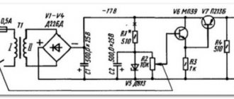
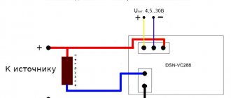
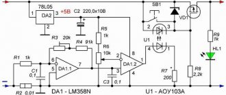
After which you need to assemble this simple circuit, which is now in front of you:
To calibrate the indicator, it is very desirable to have a laboratory power supply, but in the absence of one, you can easily limit yourself to any 6 volt power adapter. Next, you need to connect a multimeter in parallel to the power source; we will have it as a standard.
Now we apply voltage to the input and slowly rotate the trimming resistor until the arrow shows the voltage that we see on the multimeter.
That is, it is enough just to calibrate the head at a specific mark, and due to the fact that the scale is linear, our meter will also adequately display other voltage values.
Next, you need to measure the resulting resistance, and in place of the soldered trimming resistor, install a constant resistor with the same resistance.
If you do not have the required resistor at hand, you can connect several resistors in series to obtain the required resistance value.
For this project, it is advisable to use resistors with an error of 1 percent or less.
Of course, you can leave the trimmer, but before that you will need to tape the adjusting screw to prevent it from moving.
And that's all. Thank you for attention. See you again!
Author's video:
Source
Become the author of the site, publish your own articles, descriptions of homemade products and pay for the text. Read more here.
Digital voltmeter circuit
A conventional digital voltmeter circuit is based on discrete quantities. The input device plays an important role in it. In this case, the control device interacts with the digital readout unit through decimal numbers. A special feature of the input device is a high voltage divider. If the work comes down to determining the alternating current, then it works like a regular converter. In this case, the output is constant current.
At this time, the central unit is engaged in the analog signal. In this system it is presented in the form of a digital code. The conversion process is characteristic not only of voltmeters, but also of multimeters. Some device models use binary code. In this case, the process of receiving a signal is greatly simplified, and the conversion occurs much faster. Older voltmeter models worked exclusively with decimal numbers. At the same time, the measurement value was recorded. Additionally, the digital voltmeter circuit has a central unit, which is responsible for all the important components of the device.
Homemade voltmeters
You can make a voltmeter (digital) with your own hands. First of all, a detector is selected that is designed to determine the rectified average value. In this case, it is usually installed next to the AC converter. The minimum voltage detector is determined from 100 MV, however, some models are capable of recognizing current strength up to 1000 MV. Additionally, in order to make a voltmeter (digital) with your own hands, you will need a transistor, which affects the sensitivity of the device, namely its threshold. It is associated with the level of quantum voltage amplitude. The sensitivity of the device is also affected by the discreteness of the device. If the voltage is less than 100 MV, then the resistance level will certainly increase and may ultimately reach 10 ohms.
Circuit resistance
The resistance that is formed in the system depends on the number of signs in the circuit. In this case, it should be understood that the scales of voltmeters can vary greatly. The ratio of the measured quantity is directly proportional to the voltage. Additionally, you need to take into account noise immunity, which also affects the resistance of the device. It should be noted here that it is the digital built-in voltmeter that has large amplitudes.
In this case, this has a great influence on the occurrence of interference in the circuit. The most common cause of a sudden surge is considered to be improper operation of the power supply. In this case, the average frequency of the device may be disturbed. Thus, there was, for example, 50 Hz at the input to the circuit, and 10 Hz at the output. As a result, resistance is generated in the connecting wire. Gradually this leads to a leak, and this happens in the place where the terminals are located. In this case, the problem can be solved by grounding this area. As a result, the interference passes to the input circuit and the frequency in the device stabilizes.
Pulse code voltmeters
The pulse-code digital AC voltmeter operates on the principle of bit-by-bit balancing. In this case, the compensation voltage measurement method is applicable to these devices. The calculation process, in turn, is carried out using a precision divider. Additionally, the reference voltage in the electrical circuit is calculated.
In general, the compensated current has several levels. According to quantum theory, calculations are performed in the binary-decimal system. If you use a two-digit digital voltmeter for a car, the voltage is recognized up to 100 V. The entire process is carried out according to commands. The comparison of voltages deserves special attention in this work. It is based on the principle of control impulses, and they occur in the system at certain time intervals. In this case, it is possible to switch the resistance of one divider.
As a result, the output frequency changes. At the same time, it is possible to connect a separate device to compare indicators. The main thing is not to forget to take into account the size of the divider in the link. In this case, the device signal may not be received. As a result, the data can be compared by key positions. Essentially, they are a code that is read by a voltmeter.
Double integration voltmeters
The double integration digital DC voltmeter operates on the principle of periodic repetition. In this case, the return of the source code in the chain is carried out automatically. This system operates exclusively with direct current. In this case, the frequency is pre-rectified and supplied to the output device.
Sampling errors are not taken into account in voltmeters. Thus, moments of mismatch of counting pulses may occur. As a result, one parameter can be very different at the beginning and end of the interval. However, as a rule, the error is not critical due to the operation of the converter.
A particular problem is noise interference. As a result, it can significantly distort the voltage indicator. Ultimately, this is reflected in the magnitude of the pulse, namely its duration. Thus, these types are not very popular among digital voltmeters.
Digital voltmeter converters
Today, there are many different types of converters that are installed in voltmeters. The most common are time-pulse models. Additionally, there are pulse code converters.
Their distinctive feature from other devices is the ability to perform bit-by-bit balancing. At this time, pulse-frequency models are deprived of such a privilege. However, they can be used to perform spatial coding, which can be extremely important in some studies. This is especially true for voltage measurements in closed electrical circuits.