Do-it-yourself step-up/step-down voltage converter
Good day everyone, dear DIYers! In this homemade product, AKA KASYAN will make a universal step-down and step-up voltage converter.
The author recently assembled a lithium battery. And today he will reveal the secret for what purpose he made it.
Here is a new voltage converter, its operating mode is single-cycle.
The converter has small dimensions and quite high power.
Conventional converters do one of two things. They only increase or only decrease the voltage supplied to the input. The version made by the author can both increase,
and lower the input voltage to the required value.
The author has various regulated power sources with which he tests assembled homemade products.
Charges batteries and uses them for various other tasks.
Not long ago, the idea of creating a portable power source appeared. The problem statement was as follows: the device should be able to charge all kinds of portable gadgets.
From ordinary smartphones and tablets to laptops and video cameras, and even coped with powering the author’s favorite soldering iron TS-100.
Naturally, you can simply use universal chargers with power adapters. But they are all powered by 220V
In the author’s case, what was needed was a portable source of various output voltages.
But the author did not find any of these for sale.
The supply voltages for these gadgets have a very wide range. For example, smartphones need only 5 V, laptops 18, some even 24 V. The battery manufactured by the author is designed for an output voltage of 14.8 V. Therefore, a converter is needed that can both increase and decrease the initial voltage.
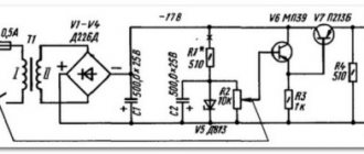
Please note that some of the values of the components indicated on the diagram differ from those installed on the board.
These are capacitors.
The diagram shows the reference values, and the author made the board to solve his own problems. Firstly, I was interested in compactness.
Secondly, the author's power converter allows you to easily create an output current of 3 Amps.
AKA KASYAN nothing more is needed.
This is due to the fact that the capacity of the storage capacitors used is small, but the circuit is capable of delivering an output current of up to 5 A.
Therefore, the scheme is universal. The parameters depend on the capacitance of the capacitors, the parameters of the inductor, the diode rectifier and the characteristics of the field switch.
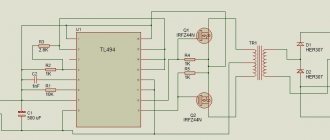
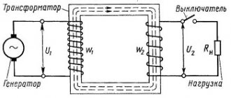
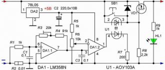
Let's say a few words about the scheme. It is a single-cycle converter based on the UC3843 PWM controller.
Since the voltage from the battery is slightly higher than the standard power supply of the microcircuit, a 12V 7812 stabilizer was added to the circuit to power the PWM controller.
This stabilizer was not indicated in the diagram above. Assembly. About jumpers installed on the mounting side of the board.
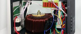
There are four of these jumpers, and two of them are power ones. Their diameter must be at least a millimeter! The transformer, or rather the choke, is wound on a yellow ring made of powdered iron.
Such rings can be found in the output filters of computer power supplies. Dimensions of the core used. External diameter 23.29mm.
Inner diameter 13.59mm.
Thickness 10.33mm.
Most likely, the thickness of the insulation winding is 0.3mm. The choke consists of two equal windings.
Both windings are wound with copper wire with a diameter of 1.2 mm. The author recommends using wire with a slightly larger diameter, 1.5-2.0 mm.
There are ten turns in the winding, both wires are wound at once, in the same direction.
Before installing the throttle, seal the jumpers with nylon tape.
The functionality of the circuit lies in the correct installation of the inductor.
It is necessary to solder the winding terminals correctly.
Simply install the throttle as shown in the photo.
The transistor current is not lower than 30A.
The author used an IRFZ44N transistor.
The output rectifier is a YG805C dual diode in a TO220 package.
It is important to use Schottky diodes, as they give a minimal voltage drop (0.3V versus 0.7) at the junction, which affects losses and heating. They are also easy to find in notorious computer power supplies.
In blocks they are located in the output rectifier.
In one case there are two diodes, which in the author’s circuit are paralleled to increase the passing current. The converter is stabilized and there is feedback.
The output voltage is set by resistor R3
It can be replaced with an external variable resistor for ease of operation.
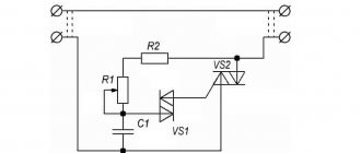
The converter is also equipped with short circuit protection. Resistor R10 is used as a current sensor.
This is a low-resistance shunt, and the higher its resistance, the lower the protection response current. An SMD option is installed on the side of the tracks.
If short circuit protection is not needed, then we simply exclude this unit.
More protection. There is a 10A fuse at the input of the circuit.
By the way, the battery control board already has short circuit protection installed.
It is highly desirable to take capacitors used in the circuit with low internal resistance.
The stabilizer, field-effect transistor and diode rectifier are attached to an aluminum radiator in the form of a bent plate.
Be sure to isolate the transistor and stabilizer substrates from the radiator using plastic bushings and heat-conducting insulating pads. Don't forget about thermal paste. And the diode installed in the circuit already has an insulated housing.
Thanks to PWM control, the efficiency of the converter is very high. For example, the no-load current, depending on the supply voltage, is in the range of 20mA - 40mA.
Let's start testing. First, let's check the output voltage ranges. Let's apply 12 V to the input. The output voltage reaches twenty-five. You can’t raise it higher, the output capacitors are 25 V.
The minimum output voltage is 4.85 V. Therefore, you can charge all USB gadgets.
Stabilization works great! By increasing the input voltage to 22.2 V, the output is exactly within the specified limits.
It is important to reinforce the wide power traces of the printed circuit board with solder. Because large currents flow there.
Links to components are in the description of the original video. Link to the original video - below the text is the “source” button. Source
Become the author of the site, publish your own articles, descriptions of homemade products and pay for the text. Read more here.
Everything with your own hands
Hello. Today I will try to please you with a review of a step-down module on the LM2596 chip. I already wrote about a step-down converter on the XL4015, LM2596 is about the same converter, only designed for a current of up to 3A. They come from China. I buy such modules for only 40 R each plus delivery. At one time I ordered a dozen, let them sit. Together with delivery, I paid 650 rubles for a dozen. You can buy the module using this link.
Well, to the module itself. I'll start with what the module itself looks like. A small scarf in itself, an entrance and an exit. The output voltage is adjusted using a variable multi-turn resistor
Before turning it on, I will indicate the main characteristics of the LM2596
Output voltage 1.23 V – 37 V Output current up to 3 A Maximum input voltage up to 40 V Conversion frequency 150 kHz Thermal protection and current limitation
First of all, I’ll connect the module to the 24V power supply, which I talked about in the laboratory power supply article. Current consumption at idle is only 24.6 mA, with most of the current consumed by the LED indicator
Now I'll try to short-circuit the output. The current consumption is only 200mA, with the same 24V supply. At this moment, Short Circuit protection is enabled
In the leftmost position of the variable resistor, the minimum output voltage is 1.3V
The maximum output voltage is 24.6V with a power supply of 25.3V. The internal drop on the chip is approximately 0.6-0.7V
Now that all the simple tests are over, we can move on to the load. The load is an MLT-2 3 Ohm resistor placed in a jar of distilled water.
In the photo below, the consumption from the power supply is 1.81A, while at the output of the LM2596 module the consumption is 3A.
Under a load of 3A, the output of the module is 9.48V, when the module is powered by 22V. You can also calculate the efficiency: 22V*1.81A-9.48V*3A=39.82W-28.44W=11.38W is the power dissipation, efficiency 71.5%
Now I’ll connect it under a 2A load. At the same time, the consumption from the power source is 0.79A.
Under a 2A load, the output voltage is 7V, supply voltage is 22.7V. At 2A load efficiency 78%
I will carry out the next test under a load of 1A. Current consumption 0.16A. In the photo you can see I made a mistake and did not take a picture of the supply voltage; the module was powered by 24V.
At the output of the 3.5V module, consumption is 1A, efficiency is 91%. It follows from this that the highest efficiency depends on the current consumption
Throughout all the tests, the module gets quite hot and it would be ideal to glue a small radiator to it with hot glue. In this option, the module will feel more adequate, although during the entire test the thermal protection did not work. Personally, my opinion is not to load the module with more than 2A
Next was another unplanned test. I tried to charge the LI-Ion 18650 battery, the module coped with the task easily. I set the power supply to 14.8V, set the output voltage to 4.19V and connected the battery via an ammeter. From the start, the current consumption was 0.8A, but after a minute it dropped to 0.68A
After 2 hours the battery was already fully charged, the ammeter doesn’t even see the current consumption)
This is such a simple to use, reliable and very cheap module. It can be used anywhere, from a voltage stabilizer in circuits, for example, a relay and a valve in homemade argon arc welding were powered from such a module, to chargers. Subscribe to or
With uv. Edward