Modern power switching transistors have very low drain-source resistances when on, which ensures low voltage drop when large currents pass through this structure. This circumstance allows the use of such transistors in electronic fuses.
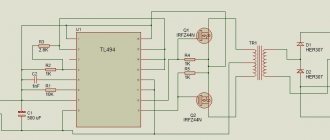
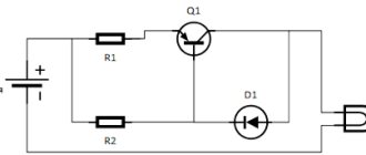
For example, the IRL2505 transistor has a drain-source resistance, with a source-gate voltage of 10V, only 0.008 Ohms. At a current of 10A, power P=I² •R will be released on the crystal of such a transistor; P = 10 • 10 • 0.008 = 0.8W. This suggests that at a given current the transistor can be installed without using a radiator. Although I always try to install at least small heat sinks. In many cases, this allows you to protect the transistor from thermal breakdown in emergency situations. This transistor is used in the protection circuit described in the article “Protection for car battery chargers.” If necessary, you can use surface-mounted radioelements and make the device in the form of a small module. The device diagram is shown in Figure 1. It was calculated for a current of up to 4A.
IRF4905 Datasheet PDF
In principle, this value also limits the minimum supply voltage of this circuit. With a drain current of 10A, it will generate a power of 2 W, which will entail the need to install a small heat sink. The maximum gate-source voltage of this transistor is 20V, therefore, to prevent breakdown of the gate-source structure, a zener diode VD1 is introduced into the circuit, which can be used as any zener diode with a stabilization voltage of 12 volts. If the voltage at the input of the circuit is less than 20V, then the zener diode can be removed from the circuit. If you install a zener diode, you may need to adjust the value of resistor R8. R8 = (Upit - Ust)/Ist; Where Upit is the voltage at the circuit input, Ust is the stabilization voltage of the zener diode, Ist is the zener diode current. For example, Upit = 35V, Ust = 12V, Ist = 0.005A. R8 = (35-12)/0.005 = 4600 Ohm.
Part 2: Insulated Gate MOSFET
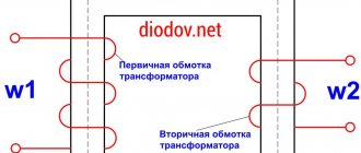
An insulated gate field effect transistor is a transistor whose gate is electrically isolated from the conducting channel of the semiconductor by a dielectric layer.
Due to this, the transistor has a very high input resistance (for some models it reaches 1017 Ohms). The operating principle of this type of field-effect transistor, as well as a field-effect transistor with a control PN junction, is based on the influence of an external electric field on the conductivity of the device.
According to its physical structure, an insulated gate field-effect transistor is called a MOS transistor (Metal-Oxide-Semiconductor), or MOS transistor (Metal-Dielectric-Semiconductor). The international name of the device is MOSFET (Metal-Oxide-Semiconductor-Field-Effect-Transistor).
MOS transistors are divided into two types - with a built-in channel and with an induced channel. Each type has transistors with an N-channel and a P-channel.
LM358 Datasheet PDF
The gain of this amplifier is equal to (R3 + R4)/R1 = 100. Thus, with a current sensor having a resistance of 0.01 Ohm, the conversion coefficient of this current-voltage converter is equal to unity, i.e. One ampere of load current is equal to a voltage of 1V at output 7 DA1.1. You can adjust the Kus with resistor R3. With the indicated values of resistors R5 and R6, the maximum protection current can be set within.... Now let's count. R5 + R6 = 1 + 10 = 11kOhm. Let's find the current flowing through this divider: I = U/R = 5A/11000Ohm = 0.00045A. Hence, the maximum voltage that can be set at pin 2 of DA1 will be equal to U = I x R = 0.00045A x 10000 Ohm = 4.5 V. Thus, the maximum protection current will be approximately 4.5A.
Current-voltage characteristics (CV characteristics) of a MOS transistor with an induced channel.
The current-voltage characteristics of a field-effect transistor with an insulated gate are similar to the current-voltage characteristics of a field-effect transistor with a control PN junction. As can be seen in graph a), initially the current Ic increases in direct proportion to the increase in voltage Uc. This area is called the ohmic region (Ohm's law applies), or the saturation region (the transistor channel is saturated with charge carriers). Then, when the channel expands almost to its maximum, the current Ic practically does not increase. This area is called the active region.
When Uc exceeds a certain threshold value (the breakdown voltage of the PN junction), the structure of the semiconductor is destroyed and the transistor turns into an ordinary conductor. This process cannot be restored, and the device becomes unusable.
Circuit operation
The scheme works as follows. For example, with a load current of 3A, a voltage of 0.01 x 3 = 0.03V will be released at the current sensor. The output of amplifier DA1.1 will have a voltage equal to 0.03V x 100 = 3V. If in this case, at input 2 of DA1.2 there is a reference voltage set by resistor R6, less than three volts, then at the output of comparator 1 a voltage will appear close to the supply voltage of the op-amp, i.e. five volts. As a result, the optocoupler LED will light up. The optocoupler thyristor will open and bridge the gate of the field-effect transistor with its source. The transistor will turn off and turn off the load. You can return the circuit to its original state with the SB1 button or by turning the power supply off and on again.
The disadvantage of the circuit is the unipolar power supply of the operational amplifier; therefore, at low values of the voltage drop across the current sensor, a large nonlinearity of the gain of the op-amp DA1.1 occurs.
Download article
DIY reverse polarity protection board
Greetings, Samodelkins!
As you know, many homemade and factory-made devices often do not have protection against incorrect power polarity, in other words, they do not have protection against power reversal. In particular, this applies to various homemade products, as well as ready-made devices, sound amplifiers, built-in sound modules, etc.
Any user, through inattention, can accidentally confuse the polarity of the power supply, after which in the vast majority of cases the device may require urgent assistance in the form of repairs. Or it may even happen that after such abuse the device simply becomes unusable, and no repair will help bring it back to life.
In order to avoid such an unpleasant situation, reverse polarity protection should be used. They are different. One of the popular options is the use of diodes or diode bridges for power supply, which are capable of passing current only in one direction and thereby preventing the possibility of polarity reversal. This is a fairly budget-friendly and simplest solution. But there is also a disadvantage to this method of protection, namely, the presence of a voltage drop across the diode. Do not forget also that at high currents and the presence of a voltage drop, the diodes heat up quite a bit and if cooling is not used, they may fail.
For example, this audio amplifier with a TDA7377 chip has a diode bridge installed.
In this case, it is primarily used here as a voltage rectifier when powered by an alternating voltage current source. But if the device is connected to a power source with a constant voltage, then this diode bridge works precisely as protection against polarity reversal. And no matter how we connect the battery, the diode bridge will prevent polarity reversal by passing current in the right direction.
And if instead of a diode bridge there was simply a positive diode, then if the power supply is connected incorrectly (polarity reversal), the diode will not pass current and the amplifier simply will not turn on.
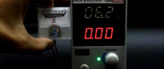
But, as mentioned above, both the diode bridge and the diode have a voltage drop. To demonstrate this, the author of the YouTube channel “Radio-Lab” measured the voltage before and immediately after the diode bridge.
As you can see, the voltage on the battery is 12.06V, and after the diode bridge the voltage is approximately 1.5V lower. It seems that the losses are not so large, but this in turn will affect the power of the amplifier, in the end it will be slightly lower and part of the battery energy will be used to heat the diode bridge.
Let's calculate the losses and heat dissipation on the diode bridge. For example, with a load current of 2A and a voltage drop across the diode bridge of 1.5V, the heat dissipation on the diode bridge will be about 3W. And additional losses are not a plus, especially when powering an audio amplifier or other device from a battery, where it is desirable to spend energy sparingly and its quantity in the battery is limited.
Here's a comparison of the voltage drop across a conventional diode:
As you can see, it is about 0.4V. On a Schottky diode, the voltage drop is already lower and amounts to 0.2V.
The voltage drop across the diode bridge is the largest and is 0.6V.
During load, voltage drops may be slightly higher. In fact, it is not often possible to reverse the polarity of the power supply, but the loss in the presence of a drop on the diodes or diode bridge will be constant and, as a result, there will be heating, which in turn leads to the need for cooling. As you can see, diodes can be used as protection against polarity reversal, they work, but you still want better protection so that there is no heating, losses are minimal, and good operating currents. The author offers one simple, but quite good power supply reverse polarity protection circuit using a powerful field-effect transistor.
This circuit is suitable for protecting devices with single-supply power. Power field-effect transistor - IRF1405 powerful N-channel.
Such a transistor is capable of switching a fairly large current and, in turn, has a fairly small resistance, which is why there will be practically no voltage drop, and, therefore, there will be almost no heating, or it will be minimal, and there will be no such losses as on diodes.
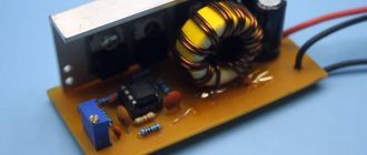
The author drew this miniature scarf for this protection scheme.
The operation of the circuit is extremely simple: if everything is connected correctly, the transistor is turned on and current flows through the transistor.
If the power polarity is not connected correctly, the transistor closes, thereby creating a break in the power circuit and the associated plus does not pass further than the transistor.
All the necessary parts for assembling the protection board were purchased on the radio market.
First of all, the author installs the 100 kOhm resistor in place and solders it.
Next, we will install zener diodes at 15V 0.5W, making sure to observe the polarity of the cathode marks.
Next, install a non-polar capacitor with a capacity of 0.1 µF.
Now the terminal blocks for power input and output.
The board is almost ready, there is only one element left - the power transistor. To install it, the author bent the legs of the transistor - like this:
And installed it in its place. The result is such a small and convenient power supply reverse polarity protection board for amplifiers and devices with single-polar power supply. Unipolar power is where there are two power wires: plus and minus. After soldering is completed, the board must be washed to remove any remaining flux so that everything is clean and beautiful.
Now let's check the functionality of the protection board we assembled. To test the board, connect a battery with a supply voltage of 12.1V to its input. The author connected multimeter probes to the output of the board. First, connect the battery correctly, observing the polarity.
As you can see, there is voltage at the output of the board, and the voltage drop is so low that the multimeter does not notice it. Now we change the polarity of the power supply and connect the battery, confusing the plus with the minus.
As you can see, the transistor has closed, the protection board has tripped and is no longer letting anything through, thereby protecting the device (in this example, a multimeter) from polarity reversal. If you connect the power correctly again, the transistor will open and the battery voltage will appear at the output of the board. Great, the board works. After we have tested the homemade board and are convinced of its functionality, we can connect the protection board to the sound amplifier. We will use the simplest amplifier on the TDA7377 microcircuit without any protection against polarity reversal, and if the polarity of the power supply is confused, then at least the polarized capacitor on the power supply will explode and the microcircuit will burn out.
The protection board is connected to the plus and minus gap of the amplifier power supply, where there is a possibility of polarity reversal. We must connect the power wires coming from the protection board to the amplifier board observing the polarity.
That's it, now our amplifier has protection, and it is not afraid of polarity reversal. Connect the power correctly.
As you can see, the LED on the amplifier lights up, everything is fine, the amplifier has power. Now, connect the power by reversing the polarity.
As you can see, nothing smoked and the LED on the amplifier board does not light up, therefore, no power is supplied to the amplifier, which means our homemade protection board is working and completely fulfills its task.
This board can be used to protect against polarity reversal of audio amplifiers with single-supply power, including class D amplifiers, portable speakers and many other devices. Remember, if there is even the slightest chance of mixing up the polarity of the power supply, then at the right time, at a minimum, protection against polarity reversal will save you money and protect your product from accidental polarity reversal and, as a result, breakdown.
It is also important to understand that in some cases it is more convenient to use diodes or a diode bridge as protection against polarity reversal, and in others, an assembled protection board; this must be looked at according to the tasks. Try, collect and repeat. The archive with the board can be downloaded HERE. Thank you for attention. See you again!
Video:
Source
Become the author of the site, publish your own articles, descriptions of homemade products and pay for the text. Read more here.