Friends, I warmly welcome you to my next instruction article. Nerd from WiFiGid is in touch. Throughout my life, I have already assembled an unlimited number of computers, but the most difficult thing that a beginner in this business can face is the final assembly. In this article I would like to share with you my experience on how to properly connect a motherboard. Step by step, in pictures, for dummies.
But if you still have any questions or comments (the world is changing, articles sometimes become outdated) - welcome to the comments. We will discuss and supplement.
I also strongly recommend preparing instructions for your motherboard - in the form of a book or downloading from the Internet for your model. While the general steps are always clear, the pinout of the front panel is sometimes not indicated on the board at all - you will have to read the instructions or waste time going through it.
Photos based on the example of my not very old ASUS B360K. But this will not affect the essence of the story.
Testing the assembly
After successful assembly, we move on to testing. It's very normal if something doesn't work. Simply listening to sounds (if you have connected a speaker) or reading messages on the screen with a translator is also a great option. The main thing here is not to be afraid.
General testing procedure:
- We turn on the power supply and in some cases the lights on the board light up. This means the board is connected to power correctly.
- Press the power button on the front. If it doesn’t work, go to the front panel connection section and fiddle with that small connector. But usually the backlight starts to light and the fans rotate.
- We immediately check the rotation of the fans: processor, video card, case fans. If something doesn't work, we look for the reason.
- While we were checking, the system (or at least the BIOS) should have already loaded - if nothing bad is written or everything has loaded, we move on. As an example, information about missing disks (checking the cable and power) or the need to connect power to the video card may be written here. Sometimes squeaks start - listen to the speaker squeak, open the instructions for your board and only then read the error codes (to put it bluntly, systems differ, instructions from other boards may not be suitable). Sometimes it’s not at all clear - in my case, it turned out that the processor came out after the board, and the board in the drain did not know about its existence and gave an error. She had to look for an old processor that she knew, flash the BIOS, and after that everything started successfully. Watch and don’t be afraid to negotiate with any service that has hardware on hand.
- In the system properties, we check the amount of RAM - everything should correspond to the installed one.
- We look at the number of hard drives - if there was no logical partitioning, everything should correspond to what was installed.
- We connect to the front USB connector - for example, a mouse or keyboard. We check the work.
- Connect headphones to the front jack.
- Click the reboot button.
The checks can be expanded further, but it is better to do this before the case is finally closed, so as not to go inside again later. Here I also run the same AIDA64 system for a stress test to check the cooling performance, but this is not for everyone.
About connecting PC elements to the motherboard
You can connect these components in any order, but it is still recommended to initially connect the power supply in order to be able to monitor the performance of the system.
In addition, some components require connection not only to the motherboard, but also to the power supply. How to install a motherboard in a system unit How to start a power supply without a motherboard
Step 1: Connecting the Power Supply
The power supply is one of the main elements of any computer. It is advisable to connect it first. The connection is made using a special cable with 24 contacts (24 pin). There are also options where the main cable has the form 20+4, then 20 main contacts and 4 additional additional ones. When installing, do not connect the power supply to the mains under any circumstances.
In addition to the main contacts on the power supply, there are additional ones that are needed to supply power to the hard drive, processor, video card, etc. In this step you will be working with a basic 24 pin cable.
Find him. It is the largest among all cables, plus, sometimes it can be highlighted in color or indicated by an appropriate inscription. Similarly, you need to find a connector for it on the motherboard. He is also larger than the others and can bear certain markings. Just connect the wire to this connector and that's it. Make sure the cable is installed tightly enough, but do not force it as you may damage the motherboard and/or cable. Some models have special latches, use them.
Step 2: Connecting Power to the Socket
Before installing the central processor and cooler into the processor socket, you need to power it from the power supply. Despite the fact that the socket is also located on the motherboard, it receives power from a separate cable. This cable has only 4 contacts (designated as 4 pin), differs from the others in its small size, as well as its pronounced square shape.
Connects to the connector located near the chipset. Make sure that you install the cable tightly into the connector; use special latches for a tighter fixation, if they are provided in the design.
Step 3: Front Panel Connection
The front panel contains power buttons, power indicators, USB connectors and audio devices. It is advisable to connect this panel immediately after you have powered the motherboard, so that you can immediately check the functionality of the entire computer.
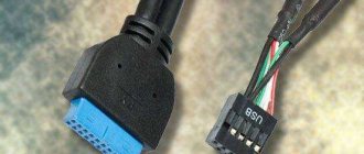
The cables presented on the front panel have 1-2 pins (contacts) and connect directly to the motherboard. They need to be connected in a certain sequence and to certain connectors. Connectors and cables have special marks, so you can hardly make a mistake, but regarding the connection sequence, you need to look in the documentation for the motherboard or front panel.
There are several cables in total:
- PowerSW – is responsible for the functionality of the power button. It can be indicated in red, white or green, less often yellow and black. Has 2 contacts;
- ResetSW – is responsible for the button to restart the computer. Usually indicated in yellow. Also has 2 contacts;
- PowerLED is a cable responsible for the operation of the power indicator. It has only 1 contact, does not have a special color designation;
- DDLED – this cable may not exist, or there may not be a connector for it on the motherboard. The cable is responsible for the functionality of the hard drive loading indicator. Has only 1 contact.
Also, cables for USB and Audio outputs can be built into the design of the front panel.
Connect the cables in strict accordance with the instructions included with the front panel or motherboard. Try to secure the contacts as tightly as possible, but do not use force, as they are very fragile.
Completion
Finally, they usually try to somehow remove the excess wires through any hole under the back cover of the case, while the coils of wire are put away in ties. And then everything is simple - the side covers are closed, and the computer goes to the last test - the hearing test. We just run it and listen so that nothing rattles against the body. Sometimes rattling can be heard even before closing, but most of the vibrations come from these covers.
This is where I finish our super review. If something is not clear, or there is something to add, be sure to write in the comments. If you have already solved your problem before I even answered, write your solution in the comments. Perhaps this will be very useful for someone else. After all, much that is obvious can be completely unobvious and an important addition for our other readers. Thank you!
Using Explorer
The monitor cable is not always suitable for connecting to the connector of the computer itself. In such a situation, a guide will help. It will also help if a port is simply missing. The conductor has two different sides - one is connected to the hole for the screen in the block, and the other is used to secure the wire of the desired connector. Using cables, the monitor is also connected to the system unit or video card.
After this, you just need to connect the computer and monitor using the selected cable and check their operation.
IMPORTANT! The adapter is inexpensive, the main thing is not to make a mistake with the holes and buy what you need for your wire and equipment.
How to choose a power supply for a computer? Power supply efficiency
The efficiency of a power supply unit is the ratio of electricity consumed from the network to the voltage supplied to the system components, while part of the energy will be lost as heat.
The efficiency of the power supply is regulated by 80 Plus certificates. There are five types: 80 Plus Bronze, 80 Plus Silver, 80 Plus Gold, 80 Plus Platinum and 80 Plus Titanium. The higher the certification, the more energy efficient it is and consumes less electricity from the network. However, the cost difference between 80 Plus Bronze and 80 Plus Titanium certified power supplies can be more than double.
For example, an 800-watt 80 Plus Bronze certified power supply at maximum load will draw 800 x (1 / 0.81) = 987 watts from the network. While the same unit with 80 Plus Titanium certification at maximum load will consume 800 x (1 / 0.91) = 879 W.
How to connect a printer, scanner, copier?
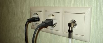
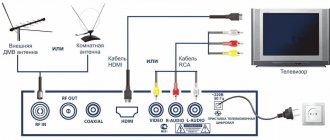
Now is a good time to connect any other peripherals such as a printer, copier/scanner or speakers. Most of these items will be connected via a USB port. However, some older printers use a pink parallel port. See picture above. Likewise, some speakers still use the green/pink circular audio jack. Use the picture above, along with the color and size, to get all your cables in the correct ports. Once all your cables are connected and you've double-checked everything, we're ready to turn on your new computer.
Wired connection
As you already understand, this material will be devoted to creating small computer networks at home or in a small office. Agree that it is better to learn the basic subtleties once, and then carry out all the settings yourself, than to invite a specialist every time and pay him a lot of money for it.
So, if you are a small entrepreneur or an enthusiast who wants to connect a friend's laptop to your computer and play your favorite games all night long, then stay with us until the end. So, let's go!
network hardware
We will start with the simplest and gradually complicate the connection diagram. This way you can better understand the meaning of the interaction of the periphery, and subsequently apply the knowledge in practice.
LAN network connector: how to connect two computers with a wire
The first thing you should know is whether your computer has a LAN network port. It looks as shown in the picture above, and you need to look for it on the back panel of your system unit, or, if you have a laptop or all-in-one, then on the side panels.
Laptop side panel
In addition to the specified connector, the side panel of the laptop may contain USB ports in varying numbers, as well as VGA and HDMI jacks, to which you can connect a wire connecting the computer and TV.
So:
- The vast majority of modern motherboards already have built-in network equipment , and its software contains all the necessary drivers necessary for the correct operation of the device.
- But many representatives of old equipment, for example, some motherboards for the LGA 775 socket, which many people still use, do not have this equipment on board . In this case, you will need a separate network card, which you can buy at any computer store.
- The price of such a card ranges from 300 to 1000 rubles , depending on the manufacturer and the card’s throughput.
- You will also have to purchase a network card if the built-in equipment fails, if you need an additional connector to connect an independent network, or to organize a server.
Network card for a personal computer
This card is installed in a PCI-Express slot, which you can find by removing the left side cover from your system unit (optional for cases of various models). This is done very simply - just unscrew the screws holding the cover on the back of the case and slide it back.
Advice! Before you begin any manipulations with the system unit, do not forget to first turn it off and disconnect it from the electrical network in order to avoid electric shock.
Motherboard: 1 – PCI-Express; 2 – terminal panel
- Removing the side cover reveals the motherboard. They can be of different sizes and colors, but the vast majority have at least one PCI-Express slot. In the photo above, there are as many as 6 of them.
- Each connector on the rear panel has a corresponding window for the board pins. If it is still blank on your PC, then break it out with pliers. Be careful and try not to touch nearby electronic circuit parts.
- Next, install the network card into the slot. Do this with noticeable pressure to ensure that the board is connected securely.
- Afterwards, secure the card with a screw if required by the design of the PC case.
Installation of network equipment
That's it, now you are ready to connect computers to the network
Direct connection
The simplest connection option is to connect two computers directly via a network cable, without using routers.
To do this, you will need a “twisted pair” wire, which can be purchased as a ready-made solution of a certain length, or taken in the required molding, followed by crimping the connectors. Salespeople at a computer store will help you complete this procedure.
Twisted pair network cable: a wire connecting two computers
We insert both ends of the wire into the LAN outputs on the network cards of the connected computers. Now all you have to do is wait until the smart system sets all the parameters and start using the network. You probably would like to hear exactly these words? But in reality, this is not a very good joke. In any case, you will have to dig deeper into the settings.
We will analyze the network debugging process using the example of today's most popular operating system, Windows 7. If you are the owner of older or newer versions, then do not rush to get upset, since the setup is no different. The whole difference lies in the location of the necessary settings, which can easily be found on the Internet.
The setup instructions will be discussed step by step, with detailed images of each stage - so doing the setup yourself will not be difficult for you.
Network configuration
Press the start button and select “Control Panel”.
We open access to all categories and settings
If a window opens in front of you with a view like in the photo above, then it will be much more convenient to go to the classic view of this panel, where all available system settings will be available. In the upper right corner, click on the “View” drop-down menu and select “small icons”.
Control panel menu
In the window that opens, we are interested in the “Network and Sharing Center” item. Find it in the list and click once with the left mouse button.
LAN Settings
Your operating system will automatically detect a new local network connection and label it as an unidentified network. If this does not happen, then just below is the item “Set up a new connection or network”. In it you can step by step recognize the network and configure it. If everything is determined automatically, then go to the highlighted item “Local Area Network Connection”.
All further steps are completely identical to the settings in other Windows operating systems, including XP.
Let's move on to setting up the network connection
A small window will open in front of you in which you can monitor the current state of the network. We are interested in the “Properties” button.
Setting up the TCP/IP protocol
In the next window you can choose between network services and protocols. We are interested in one single item called “Internet Protocol Version 4 (TCP/IPv4)”. Double-click on it with the left mouse button and go to the IP address settings menu.
Protocol settings
You see before you the properties of the Internet Protocol, where we will manually set a unique computer name, called an IP address. It is required for the system to correctly recognize computers on the network. If this is not done, or it happens that two PCs have the same addresses, then an IP address conflict will occur and the network will not work.
So:
- The first step is to change the label to “use the following IP address”.
- Next, enter the IP value in the following format. The address consists of four numbers separated by dots: enter them one by one, following the position of the cursor: 192.168.0. n, where n is any value from 1 to 255. The main thing is that the selected number does not coincide with the number on the second computer.
- The next step is to click on the “Subnet Mask” field. It will automatically fill in and set the value: 255.255.255.0
Next, click “OK” and close all windows. Now we need to set the workgroup name. To do this, right-click on the “My Computer” icon and select “Properties”.
The following window will open in front of you, where we need the “Advanced system settings” item.
My computer: properties
In the window that opens, select the “Computer name” tab.
Computer name
In the open tab you will see the following items. We need an "Edit" button. By clicking on it, you will see a window where you can set a new computer name and workgroup name. We are interested in the second.
Setting up the workgroup name
Unlike the IP address, the workgroup name must be identical on all machines included in the network. It is written in capital letters of the Latin alphabet. The most commonly used names are MSHOME or WORKGROUP. But you are free to set the name yourself at your own discretion.
At this point, the network setup is complete, and its current configuration will allow you to open access to the printer, folders and even the Internet, but this is a topic for another article.
Connection via switch
The instructions given for setting up a network connection apply to any type of connection - be it a separate cable or a multiport router. A switch or network concentrator (hub) is a device of the same type designed to branch a signal and connect two or more computers into a network.
8 port con
For the average ignorant user, a switch is a small plastic or metal box with a bunch of blinking lights. A knowledgeable person can easily connect several computers to a network using it.
Hubs are available in different types, and can be designed to connect both a small number of computers and fairly large networks. The price of such devices primarily depends on these parameters.
Wire connectors for connecting a computer and laptop
We have at our disposal an old Chinese hub that supports networks at speeds of up to 100 Mb/s.
Let's use his example to analyze the structure of such devices:
- On the front cover of the hub there is a light indication of the network status. This information board will allow you to easily identify all correctly functioning network elements.
- On the rear panel there are connectors for connecting cables from computers. They are designated: 1x, 2x, 3x... etc.
- One of the connectors may be marked as “UP-Link” - it is not an independent port, but duplicates one of the standard ones (usually the first or last), and is intended for daisy-chaining several hubs into one chain.
- Some hub models may have an MDI/MDI-X switch, which switches the socket layout from the standard state to UP-Link mode. This technique allows manufacturers to save on ports.
- There are also often models with automatic connection recognition. They are marked “Auto-MDI”. This feature is very convenient and does not require user intervention.
Using the UP-Link connector, you can connect any number of computers to the network. It is enough to connect one end of the cable to the standard output of the first hub, and the other to the corresponding socket on the second.
How to connect two computers to a network with a wire
To make a connection, connect all existing computers using a twisted pair cable to the switch, taking one at a time the free slots.
Connecting the switch
Next, connect the device to the electrical network, and perform the settings already described on all connected PCs. Remember that IP addresses must always be unique. Therefore, in order not to get confused, assign a serial number to each machine, which you enter into the settings. Now you can be online as a whole group.
Assembling a computer part 3 connecting wires
The case wires were described in detail in the article “Description of case connectors”. Each motherboard has a completely individual connection to the case wires, so open the manual for your motherboard and find the connection diagram there. Next, following the diagram, connect the case wires.
If there are no instructions, then you can always find them on the Internet on the website of the motherboard manufacturer.
Below is a photo of the connected body wires.
Next, we connect the wires of external usb and external audio inputs/outputs, here we also check the instructions for the motherboard.
Now we connect the additional processor power connector. The power supply has a special output with 4 wires, so we connect it to the additional processor power socket.
The figure shows a white four-pin connector. There is a special key on it that prevents incorrect connection.
Connecting a video card
If you are using a processor with an integrated video card, then there will be no video card connection. But most often, users prefer to use powerful graphics platforms that connect via a PCI-E connector and require additional power.
The video card is powered from a 4-pin connector. The power supply location, depending on the video card model, may be somewhere on the side, but most often it is located at the back. If the video card is very powerful and requires power, then it can be powered from a 6-pin connector. Therefore, when choosing a power supply, pay attention to exactly which and how many power wires it has. When connecting the card, the connector should snap into place - pay attention to this.
How to clean up your PC case - perfect cable management
Many advanced users can now assemble a system unit on their own. The PC is assembled, and the assembler immediately forgets what’s inside, moving on to installing the operating system. And wires may remain hanging inside. Why this is bad and how to put things in order in the three types of housing will be discussed in this article.
Hanging wires can block air movement. It's even worse if they get into the fans and stop them from rotating. To avoid this, you need to take care of cable management inside the system unit.
Careful placement and fixation of wires will not only save you from many problems and reduce noise levels, but will also help in case of maintenance and repairs in the future. In addition, in cases with transparent walls and backlighting, the mess in the wires is especially noticeable.
Why connect your computer to your TV at all?
When you connect a PC to a TV, the latter begins to act as a monitor. What capabilities does this provide to the user? First of all, of course, watching movies and TV series on a convenient big screen. You can watch your favorite movie alone at the computer desk, but for family gatherings a TV and a cozy sofa are more suitable.
It is much more difficult for a family to gather behind a small computer monitor
The second purpose is to turn the computer into something like a game console. If you have a large, high-quality TV, but do not have a good monitor, then you can appreciate modern games with cool graphics by connecting your PC to the TV. Of course, this won't improve your computer's performance, but it can significantly increase resolution, especially if you have an older monitor.
Don't forget about home photo and video presentations! If relatives have come to visit you and you want to please them with high-quality family photos, then you can’t think of a better platform for this than TV. By connecting your PC to it, you can display your photo archives in a more impressive format.