Starting current and its multiplicity
To move (start) the engine, you need a huge starting current (Ip). Enormous - compared to the rated (operating) current In at steady speed. Articles usually indicate that the starting current exceeds the operating current by 5-8 times. This number is called “Starting current multiplicity” and is designated as coefficient Kp = Ip / In.
Starting current is the current that the electric motor consumes during starting. You can find out the starting current by knowing the rated current and the Kp coefficient:
Iп = Кп · In
The rated current is always indicated on the motor nameplate:
Rated motor current for different voltages and circuits
Gearbox is an operating parameter that is indicated in the engine characteristics, but it is never indicated on the engine body.
I note that there is no need to confuse rated and operating currents. The rated current is the current at which the motor can operate for a long time; it is limited only by heating the stator winding. The operating current is the real current in a given unit; it is always less than or equal to the rated one. In practice, operating current is measured using a clamp meter, ammeter or current transformer.
If the operating current is greater than the rated current, expect trouble. Read my article about how to protect an electric motor from overload and overheating.
Multiplicity of starting current. It is usually not on the nameplate, but it is present in the documentation and on manufacturers’ websites:
Engine parameters. Starting current ratio
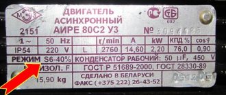
Example from the first line in the picture: a specific 1.5 kW motor has a rated current of 3.4 A. This means that the starting current at some point (how long this “moment” lasts - we’ll look at it below) can reach a value of 3.4 x 6 .5 = 22.1 A!
Judging by the catalogs (they can be downloaded at the end of the article, as usual with me), the starting current exceeds the rated current in the range from 3.5 to 8.5 times.
The starting current multiplicity depends primarily on the engine power and the number of pole pairs. The lower the power, the lower the starting current. And the fewer pairs of poles (the higher the rated speed), the greater the starting current.
That is, high-speed motors (3000 rpm, 2 pairs of poles) of relatively high power (more than 10 kW) have the highest starting current (7 - 8.5 from the nominal value).
This happens because the current consumption and moment of inertia at start-up depend on the design of the motor and the winding method. Few poles - low winding resistance. Low resistance - high current. In addition, high-speed engines require more time to fully rev up, and this is again a difficult start.
To explain it in more scientific language, it goes like this. When the engine is stationary, its slip degree S = 1. When spinning up (or, as experts like to say, unwinding), S tends to zero, but never reaches it - that’s why the motor is called asynchronous, because the rotation of the rotor will never catch up with the rotation of the stator field due to losses. At the same time, the rotor core is saturated with a magnetic field, the self-induction emf and inductive resistance increase. This means the current decreases.
For those who want to know more, at the end of the article I have posted several good books on the topic.
In fact, it’s not that simple, let’s start digging deeper.
How to calculate starting current
The amount of starting current required to drive the engine is significantly (sometimes 8-10 times) higher than the current supplied for normal operation. The result of a sharp increase in energy consumption is a drop in voltage in the power supply networks, which can lead to:
It is possible to minimize the negative impact by using additional devices. The parameters of auxiliary equipment are determined based on the starting current value for a given engine model.
You can figure out how to calculate the starting current of an electric motor yourself by reading the technical documentation for the unit and the calculation formulas. First you will need to determine the rated current (IH, depending on the motor type). For this, the following formulas are provided (all the necessary data is in the technical data sheet for the equipment):
Next, the actual value of the starting current (IP) is calculated using the formula Кп (multiplicity of direct current to the rated value, indicated in the technical documentation) * IH.
Ways to reduce inrush current
The problem of reducing the starting current and smoother voltage supply is solved using special equipment:
A competent approach to calculating the starting current value for an electric motor will allow you to get accurate results and select the most effective means of protecting the switching line.
Starting currents of asynchronous electric motors | Useful articles - Kabel.RF
The current needed to start an electric motor is called starting current. As a rule, the starting currents of electric motors are several times higher than the currents required for operation in a normally stable mode.
Asynchronous electric motor A large starting current of an asynchronous electric motor is necessary in order to spin the rotor from standstill, which requires much more energy to be applied than to further maintain a constant number of its revolutions. It is worth noting that, despite a completely different operating principle, single-phase DC motors are also characterized by large starting currents.
High inrush currents for electric motors are undesirable because they can result in short-term power shortages for other equipment connected to the grid (voltage drop).
Such measures also make it possible to reduce the level of costs for starting an electric motor (use wires of a smaller cross-section, stabilizers and diesel power plants of lower power, etc.).
One of the most effective categories of devices that alleviate difficult starting conditions are soft starters and frequency converters.
Their ability to maintain the starting current of AC motors for a long period—more than a minute—is considered especially valuable.
Calculation of the starting current of an asynchronous electric motor
Figure 2. Asynchronous electric motor with a frequency converter Calculation of the starting current of the electric motor may be required in order to select suitable circuit breakers that can protect the switching line of a given electric motor, as well as in order to select additional equipment (generators, etc.) suitable for the parameters.
The calculation of the starting current of the electric motor is carried out in several stages:
Determination of the rated current of a three-phase AC electric motor according to the formula: In=1000Pn/(Un*cosφ*√ηn). Рн here is the rated power of the engine, Un is the rated voltage, and ηн is the rated efficiency. Cosφ is the rated power factor of the electric motor. All this data can be found in the technical documentation for the engine.
Calculation of the starting current value using the formula Istart = In*Kpusk. Here In is the rated current value, and Startup is a multiple of the direct current to the rated value, which should also be indicated in the technical documentation for the electric motor.
Knowing exactly the starting currents of electric motors, you can correctly select circuit breakers that will protect the switching line.
Calculation of the possibility of starting a 380 V electric motor
This article will consider the change in voltage (loss of voltage) when starting an asynchronous motor with a squirrel-cage rotor (hereinafter referred to as the motor) and its effect on changes in voltage at the terminals of other electrical receivers.
When the engine is turned on, the starting current can exceed the rated current by 5-7 times, which is why turning on large engines significantly affects the operation of receivers connected to the network.
This is explained by the fact that the inrush current causes a significant increase in voltage losses in the network, as a result of which the voltage at the receiver terminals is further reduced. This is clearly visible in incandescent lamps, when the luminous flux sharply decreases (light flickering). At this time, running engines slow down and, under some conditions, may stop altogether.
In addition, it may happen that the starting engine itself, due to a strong voltage drop, will not be able to deploy the mechanism attached to it.
In = Pн/(√3Uн x сosφ), kA
where Pn is the rated power of the engine, kW, Un is the network voltage, kV (0.38 kV). Power factor (cosφ) – engine nameplate values.
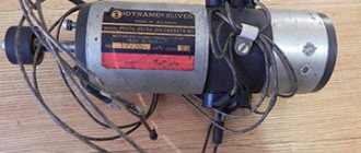
Rice. 1. Electric motor passport.
If the power factor of the motor is not known, then its rated current with a small error is determined by the ratio “two amperes per kilowatt,” i.e. If the rated power of the motor is 10 kW, then the current it consumes from the network will be approximately 20 A.
For the motor mentioned in the figure, this ratio also holds (3.4 A ≈ 2 x 1.5). More accurate current values when applying this ratio are obtained with electric motor powers of 3 kW and above.
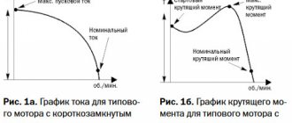
When the electric motor is idling, a small current is consumed from the network (no-load current). As the load increases, the current also increases. As the current increases, the heating of the windings increases. Large overload leads to overheating of the motor windings, and there is a risk of failure of the electric motor.
When starting from the network, the electric motor consumes a starting current Istart, which is 3 to 8 times higher than the rated current. The characteristic of the current change is presented on the graph (Fig. 2, a).
Rice. 2. Characteristics of changes in the current consumed by the electric motor from the network (a), and the effect of high current on voltage fluctuations in the network (b)
actual value of the starting current for an electric motor is determined by knowing the magnitude of the starting current multiplicity - Istart/Inom. The starting current multiplicity is a technical characteristic of the engine, it is known from catalogs. The starting current is calculated according to the formula: I start = Ix. x (Istart/Inom).
Understanding the true value of the starting current is necessary for selecting fuses, checking the activation of electromagnetic releases during engine starting, when selecting circuit breakers, and for calculating the magnitude of the voltage drop in the network during start-up.
A large starting current causes a significant voltage drop in the network (Fig. 2, b).
If we take the electrical resistance of the wires laid from the source to the electric motor equal to 0.5 Ohm, the rated current Iн = 15 A, and the starting current Iп equal to five times the rated one, the voltage loss in the wires during starting will be 0.5 x 75 + 0.5 x 75 = 75 V.
At the terminals of the electric motor, as well as at the terminals of nearby operating electric motors, the voltage will be 220 - 75 = 145 V. This decrease in voltage causes braking of the operating electric motors, which entails an even greater increase in the current in the network and failure of the fuses.
In electric lamps, when electric motors start, the intensity decreases (the lamps “blink”). Therefore, when turning on electric motors, they strive to reduce starting currents .
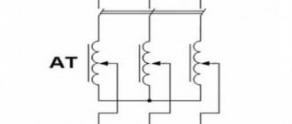
To reduce the starting current, an electric motor starting circuit is used with switching the stator windings from star to delta.
Rice. 3. Scheme for starting an electric motor with switching the stator windings from star to delta.
It is of fundamental importance that not every engine can be switched on according to this scheme. Widespread asynchronous motors with an operating voltage of 220/380 V, including the motor shown in Figure 1, will fail when switched on according to this circuit.
To reduce the starting current of electric motors, special processor-based soft start devices (soft starters) are vigorously used.
Battery inrush current
It is not for nothing that the battery is considered one of the important elements of a car. Its main function is to supply voltage to existing electrical equipment. This is mainly the starter, car radio, lighting and other devices. In order to successfully solve this problem, the battery must not only accumulate, but also maintain charge for a long time.
One of the main battery parameters is the starting current. This value corresponds to the parameters of the current that flows in the starter at the time of its start. The starting current is directly related to the operating mode of the vehicle. If the vehicle is driven very frequently, especially in cold conditions, then the battery must have a high starting current. Its nominal parameter is usually in accordance with the power of the power source supplied for 30 seconds at a temperature of minus 18 C. It appears at the moment when the key is turned in the ignition switch and the starter begins to operate. The current value is measured in amperes.
Starting currents can be completely different for batteries that are identical in appearance and basic characteristics. This factor is significantly influenced by the physical properties of the materials used for manufacturing and the design features of each product. For example, an increase in current can be observed if lead plates become porous, their number increases, or phosphoric acid is used. An overestimated current value does not have a negative effect on the equipment; it only helps to increase starting reliability.
Smooth start of an electric motor diagram
Star and delta connection of electric motor windings
Frequency converters: operating principle
Synchronous motor device
Asynchronous motor with squirrel-cage rotor diagram
Source
Electric motor power calculation
Calculation of electric motor power by current can be done using our online calculator: The result obtained can be rounded to the nearest standard power value.
Standard values of electric motor power : 0.25; 0.37; 0.55; 0.75; 1.1; 1.5; 2.2; 3.0; 4.0; 5.5; 7.5; eleven; 15; 18.5; 22; thirty; 37; 45; 55; 75 kW, etc.
Engine power is calculated using the following formula:
P=√3UIcosφη
- U - Rated voltage (voltage to which the electric motor is connected);
- I - Rated current of the electric motor (taken from the passport data of the electric motor , and in their absence is determined by calculation);
- cosφ - Power factor - the ratio of active power to total power (taken from 0.75 to 0.9 depending on the power of the electric motor);
- η - Efficiency factor - the ratio of the electrical power consumed by the electric motor from the network to the mechanical power on the motor shaft (taken from 0.7 to 0.85 depending on the power of the electric motor);
Operating modes of electric motors
The operating mode determines the load on the electric motor. In some cases it remains virtually unchanged, in others it may change. The nature of the expected load must be taken into account when choosing an engine. Current standards provide for the following operating modes:
Mode S1 (long-term). In this operating mode, the load remains constant for the entire time until the temperature of the electric motor reaches the required value. Drive power is calculated using the formulas given above.
Mode S2 (short-term). When operating in this mode, the engine temperature during its switching on does not reach the steady-state value. During shutdown, the electric motor cools down to ambient temperature. During short-term operation, it is necessary to check the overload capacity of the electric drive.
Mode S3 (periodically-short-term). The electric motor operates with periodic shutdowns. During periods of switching on and off, its temperature does not have time to reach the set value or cool down to the ambient temperature. When calculating engine power, the duration of pauses and losses during transition periods must be taken into account. When choosing an electric motor, an important parameter is the permissible number of starts per unit of time.
Modes S4 (periodically short-term, with frequent starts) and S5 (periodically short-term with electric braking). In both cases, the engine operation is considered according to the same parameters as in operating mode S3.
Mode S6 (periodically-continuous with short-term load). Operation of the electric motor in this mode involves operation under load, alternating with idling.
Mode S7 (intermittent-continuous with electric braking)
Mode S8 (periodically-continuous with simultaneous change in load and rotation speed)
Mode S9 (mode with non-periodic changes in load and rotation speed)
Most models of modern electric drives, which have been in operation for a long time, are adapted to changing load levels.
How to find out the starting current?
The starting current multiplicity (the ratio of the starting current to the rated current) is not so easy to find in the engine documentation. But you can measure (evaluate, find out) yourself. Here are a few ways off the top of your head:
- The first way (the best) is to use an oscilloscope. Take a shunt (for example, a 0.1...0.5 Ohm resistor, the smaller compared to the windings, the better), and look at the oscillogram on it at the time of start-up. Next, from the maximum amplitude value, we determine the effective voltage (divide by the root of 2), then, according to Ohm’s law, we calculate the starting current. You don’t have to multiply or divide anything - just measure the current with clamps in operating mode, and multiply it by the difference in currents on the oscilloscope screen. The good thing about this method is that you can see transient processes caused by self-induction emf, instantaneous current values, and acceleration duration. In addition, the parameters of the supply network are taken into account. Another plus is that the starting current is measured real, on a real engine and mechanism.
- The second way to measure the starting current is to apply a reduced (5-10 times) operating frequency voltage to the motor and measure the current. Why reduced? This is necessary so that the rotor can be easily fixed without overheating. Recalculate the measured current to obtain the starting current. It is enough to measure the current in one phase. For others, the currents will be (must be) the same. This method is used in the production and testing of engines. It is in this way that manufacturers obtain tabular data. The method is based on the rated current; in reality (on a real mechanism) the starting current may be different!
- Measure the starting current with a clamp meter. The advantage of this method is simplicity and efficiency. Pincers are used in most cases to check engine operating conditions. The downside is that such pincers are quite inertial, and we need to see what is happening in a split second. But this minus is leveled out when we measure the current when starting a load with a high moment of inertia (fans, pumps with massive impellers). The start-up lasts more than 10 seconds, and everything is visible on the ticker screen.
- Current transformer. This is used, for example, in electricity metering units - thanks to the current transformer, there is no need to measure the real current, but you can measure the current reduced by a precisely known number of times. They also measure current in electronic starting devices (frequency converters, soft starters). The disadvantage of this method is that the current transformer is designed for a frequency of 50/60 Hz, and transient processes during startup have a wide spectrum and many harmonics. Therefore, we can say that this method also has high inertia.
Of course, reality is different from experiment. First of all, the short circuit current of a real power supply network is not infinite. That is, the wires supplying the engine have a resistance at which the voltage drops at the moment of starting (sometimes by up to 50%). Because of this limitation, the actual starting current will be less and acceleration will take longer. Therefore, you need to understand that the value of the starting current multiplier specified by the manufacturer will always be less in reality.
What are engines for - to power machinery and make a profit!
Now let's look at another question -
What is motor starting current
If you take any technical data sheet for the engine, then in addition to the operating current, power, revolutions, type of pole connection and voltage, you can find such a parameter as starting current. In this article I want to dwell in detail on this parameter and tell you what it is and how you can measure the starting current of a real motor. So, let's begin.
Starting current and its multiplicity
So, first, let's give a definition. Starting current is the current consumed by the electric motor at the moment of its starting (spin-up). In most cases, this current is 6-8 times greater than the operating current. The value showing how many times the starting current is is called the multiplicity and is written as a coefficient:
It turns out that if the coefficient is known, then the starting current is extremely easy to find using this formula:
Note. Please do not confuse rated and operating currents. The rated current is the current at which the motor is able to operate for a long time and is limited only by the thermal heating of the stator. And the working current is the real current flowing through the windings during operation of the unit and it is always equal to or slightly less than the rated current.
The multiplicity of starting currents has a direct dependence on the power of the engine itself and on how many pairs of poles are implemented in it. That is, with less power there will be less starting current. And in the case of pairs of poles, the fewer there are, the greater the starting current.
It turns out that motors with a speed of 3000 rpm, two poles and a power of more than 10 kW (7-9 times the nominal) have the highest starting current.
Why is this happening
The thing is that current consumption and inertial torque at startup depend on the design features of the engine and on how the windings are wound.
Few poles mean minimum winding resistance. Such low resistance automatically means high current. And high-speed engines need more time to fully reach operating parameters, and this automatically makes the start difficult.
To put it in more literate language, in a static position any engine has a slip degree equal to S = 1. During the spin-up cycle, this parameter tends to zero, but never reaches it, since there are losses in the engine, and the rotor rotation speed will never reach rotation speed of the electromagnetic field of the stator (therefore the motor is asynchronous).
In addition, the rotor core goes through a stage of saturation with a magnetic field, as a result of which the self-induction emf increases and the inductive resistance and current decreases.
How to find out the magnitude of the starting current
If information on the starting current multiplicity of a particular motor is not available, then it can be measured in the following ways:
1. First way
, the most accurate, but it requires a lot of equipment. To do this, we connect the shunt and use an oscilloscope to look at the oscillogram on the shunt at the moment the engine starts. Then we divide the maximum amplitude value by the root of 2 (we get the effective value), then we carry out the calculation using Ohm’s law. Using clamps, we measure the operating current and multiply the resulting value by the difference in currents on the oscilloscope screen. This method is good for everyone.
2. Second way
. To do this, we apply a voltage to the motor that is 5 to 10 times lower than the rated voltage and measure the current. Why use reduced resistance? Yes, that's all for that. to fix the rotor, that is, to prevent it from overheating. We simply recalculate the resulting current value and obtain the starting value. This is exactly the method that manufacturers themselves use and obtain tabular values.
3. Third way
. We measure the starting current with a current clamp. This is the simplest measurement option, but at the same time the roughest, since during such a measurement the clamps do not take into account all the transient processes that occur during startup, and the device itself is quite inertial. But they are well suited for measurements when motors with a high moment of inertia (fans, pumps with large impellers, etc.) are started, when the starting torque lasts more than 10 seconds.
What is the harm from inrush current?
Inrush current is a problem. This -
- overload of the supply network, leading to heating (up to the contacts burning out) and voltage sags;
- excessive wear, overload and overheating of the engine; some manufacturers indicate among the engine parameters the maximum number of starts per hour or per day - precisely because of overheating;
- wear and overload of the mechanical drive (bearings, gearboxes, belts), especially those with a large moment of inertia,
- interference caused by the activation of contactors, which are transmitted not only through wires, but also through an electromagnetic field,
- problems with technology - many processes cannot be started abruptly.
The starting current overloads everything, and the moment of starting becomes a burden to all participants in the process. It is at this critical moment that a “weak link” may appear. In addition, many power participants operating on this network experience problems - for example, light bulbs dim due to low voltage, and controllers can freeze due to strong interference.
And at the same time, starting current is a problem that cannot be avoided if you immediately supply the motor with rated power and do not use special methods.
So let's figure it out
What determines the starting current of a car battery?
We have already figured out what the starting current should be for an average battery, but how do manufacturers achieve its increase while maintaining the same body size?
Of course, by increasing the area of the plates, you can achieve a corresponding increase in power, but there is practically nowhere to move in this direction. On the contrary, there is a tendency to reduce the size of modern batteries. How is it possible to maintain and even increase the starting current of the battery?
Let's look at specific examples. Chinese batteries have about 30% less power than their European counterparts. Manufacturers from the Middle Kingdom save on the quality of the material from which the plates are made: instead of pure lead, they use alloys with additives. In addition, Chinese batteries have 4 plates in one tank, while European batteries have 5 plates.
To charge a battery with fewer plates, more charging current is required, which negatively affects battery life.
The tightness of the housing is also important, especially in relation to maintenance-free batteries - excessive loss of electrolyte negatively affects the service life of both the power source itself and the surrounding elements of the engine compartment.
They try to increase the starting current by reducing the thickness of the housing walls, which affects the strength characteristics of the device. Below we will look at what the starting current of a car battery affects, but for now we will focus on how you can independently determine the value of the DC.
High inrush current problem: solution
High inrush current can cause a sudden, albeit short-term voltage drop, causing other devices connected to the network to experience a lack of power. This is undesirable because it negatively affects the safety of operation and the durability of the equipment.
To solve the problem, special additional devices are provided, the installation of which during the process of connecting and adjusting the engines allows:
- reduce the starting current as much as possible;
- improve startup smoothness;
- reduce the cost of starting the unit, since it becomes possible to use less powerful diesel power plants, stabilizers, wires with a smaller cross-section, etc.
The most effective are modern devices such as frequency converters and soft starters. They provide a high (more than a minute) duration of maintaining the inrush current.
How to reduce the starting current of an asynchronous motor
The problem of high inrush current can be solved electrically in two ways:
- First, apply a reduced voltage to the motor, and then, as it accelerates, increase the voltage and rotation speed to the nominal value. This method is used in electronic engine starting devices - soft starters (soft starters) and frequency converters (frequency converters).
- Use starting current limiters when, when starting, the engine is powered through powerful resistors, and then switches to nominal using a timer. The resistance of the resistors is commensurate with the resistance of the starter winding (units of Ohm, depending on the power). This device is easy to make yourself (contactor + time relay).
- Immediately apply full voltage, but first connect the windings in such a tricky way that the engine does not spin up to full power. And only when in this mode the engine spins up as much as possible, turn it on at full speed. This scheme is called “Star - Triangle”, read the next article.
You can design some kind of clutch, gearbox, variator - in order to spin the engine idle, and then connect a mechanical torque consumer.
In modern equipment, motors more powerful than 2.2 kW are almost never directly switched on, so inrush currents do not play a role for them. To reduce the starting current (and not only), frequency converters are mainly used, which will be discussed in separate articles.
Subtransient current and protection setting
- The peak value of subtransient current can be extremely high. Typically this value is 12-15 times the rms nominal value Inm. Sometimes this value can be 25 times the Inm value.
- Circuit breakers, contactors and thermal relays are designed to start motors at extremely high subtransient currents (subtransient peak value can be up to 19 times the rms rated value Inm).
- If the overcurrent protection suddenly trips during startup, this means that the starting current goes beyond normal limits. As a result, switchgear parameters may be reached to their limits, service life may be shortened and even some devices may fail. To avoid such a situation, it is necessary to consider increasing the rated parameters of switchgears.
- Switchgears are designed to protect motor starters from short circuits. Depending on the risk, the tables show combinations of circuit breaker, contactor and thermal relay to provide type 1 or 2 coordination.
Thermal effect of starting current
If we move on to the formulas, the starting current has a thermal effect on the electric motor, which is described by the so-called Joule integral. Simply put, the thermal energy produced by an electric current is proportional to the square of the current multiplied by the time. This quantity is denoted by I2t.
The good news is that the circuit breaker has approximately the same thermal (time-current) characteristic as the time-current characteristic of motor acceleration.
Compare:
Time-current characteristics of the circuit breaker
What do we see? To protect the engine, automatic machines with characteristic D are mainly used, precisely in order to react less to short-term overloads. Read more here.
And for the motor starting current the graph will be something like this:
Starting current graph (theoretical) at Kp = 6
The linearity of the graph is conditional. It all depends on the change in load torque during acceleration. The theoretical graph is shown with a dotted line. On this graph Kp = Ip / In = 6, but this is a theoretical (tabular) value. Acceleration time to nominal = tп.
The actual graph is drawn with a solid line. On it Iп` is the real value of the starting current, which is always less than the theoretical one. This is due to the fact that the supply network has non-zero resistance, and as the current increases, voltage losses occur on the wires.
I wrote about losses at low voltage here, and about losses in 0.4 kV networks here.
It is clear that due to losses, the acceleration time will be longer; it is indicated on the graph by tп`.
Now let's rotate the last graph to bring the axes to the same coordinate system:
Time from current, so to speak
Isn’t it very similar to the time-current characteristic of a protective motor?
It turns out that both characteristics compensate each other, and when choosing a machine, it is enough to adjust its setting to the rated current of the motor. For particularly difficult starts, when the area under the motor starting curve is greater than the area under the curve of the circuit breaker, it is worth thinking about a soft start - soft starter or inverter.
Starting currents
Do you want a voltage stabilizer, uninterruptible power supply or generator to operate without failure? Then this article will be useful for you.
One of the main characteristics of household appliances is the electrical power output. It reflects the ability to power the connected load. To correctly select an AC voltage stabilizer, UPS or generator, you need to know the power of the device. To calculate it, you need to calculate the sum of the electrical power of all devices that can be connected at the same time.
One of the main conditions for long and stable operation of the stabilizer, generator and UPS: the power of the equipment should not exceed their output power capabilities. It is better that the total electrical power of electrical appliances that operate simultaneously is 20% less than the output power of the power supply device. The less the stabilizer or UPS operates under overload, the longer it lasts.
The main difficulty lies in calculating the total power. The passport of any device indicates the power in kW. It seems that everything is simple: you need to add up the power of the devices. But therein lies the main mistake.
Devices that have electric motors, pumps or compressors in their design, at the moment of startup, place a load on the network that exceeds the nominal value by 2–7 times. This phenomenon is due to the presence of inrush currents.
The same rule applies to devices that include inertial components or elements whose physical properties at the time of startup differ from their normal values during operation. A classic example is the change in resistance of an ordinary incandescent lamp.
The design of such lamps contains a tungsten filament; when turned on, the electrical resistance of the tungsten is less (the filament is cold) than during operation. Resistance increases with increasing temperature, therefore, when the lamp is turned on, its power is much greater than during operation. When an incandescent lamp is turned on, inrush currents are present.
The power of any device is calculated as the product of voltage (in volts) and current (in amperes).
As the current increases, the power increases, which means the load on the stabilizer, generator and power source increases.
The definition of starting currents can be formulated as follows: electrical appliances or their elements that have inertial properties, at the moment of starting, place a greater load on the electrical network or power supply than during operation.
The value of starting currents depends not only on the effort to spin the motor or pump rotor to rated speed, but also on the change in conductor resistance. The lower the resistance, the greater the amount of current that can flow through it. When heated, the resistance decreases and the ability of the conductor to pass large currents decreases.
In addition to torque and electrical resistance, inductive power provides additional electrical power to the device at the moment of starting. When the fluorescent lamp is turned on, the inductive coil has low resistance. There is also power to ignite the discharge, which increases the current.
The influence of inrush currents is especially important for voltage stabilizers and on-line uninterruptible power supplies. Stabilizers operate in one of two operating modes: nominal or limit.
In nominal operating mode, power is maintained, but when the quality of power supply deteriorates in the network, very low or, conversely, very high voltage is observed.
In this case, the stabilizer goes into maximum operating mode, its output power is reduced by approximately 30%. If an overload of starting currents occurs, it will turn off and the protection system will work.
If this is repeated frequently, the service life of a high-quality stabilizer will be short (let alone Chinese technology).
With on-line UPS, things are more complicated. If such a device is subjected to a load that exceeds the rated load (and inrush currents have a very high speed, and they pass any protection), the fuses do not have time to operate, and the power source may burn out. This is a non-warranty case and repairs will cost a significant amount.
The only type of UPS that can withstand inrush currents 2-3 times higher than the rated value is line-interactive backup power supply systems.
The maximum starting currents are given by refrigerator compressors (single-chamber - up to 1 kW, double-chamber - up to 1.8 kW), as well as deep-well pumps. Their power during startup exceeds the nominal value by 5–7 times.
The smallest starting factor (equal to 2) is observed for Grundfos pumps with a soft start system.
When choosing power supplies or a voltage stabilizer, you need to take into account the time factor of the influence of inrush currents. When you first turn on the stabilizer or generator, all electrical appliances will start working simultaneously and the total load will be large.
During further work, the consumer must evaluate the likelihood of simultaneously starting devices with high starting currents (for example, a refrigerator, pump and washing machine).
If the stabilizer or UPS has low power, then you should independently control the switching on of equipment with inrush currents.
Conclusions:
Inrush currents can be associated with the start of a bicycle's movement: when it starts to move, it takes a lot of force to spin the wheels, but once the bicycle starts moving, less force is required to maintain speed.
Examples of rated power and starting power of household appliances
The table does not reflect the exact values of electrical appliances; only approximate figures are provided for understanding the algorithm for choosing a voltage stabilizer and UPS.
How to measure starting current
Today there are a large number of clamp meters (multimeters) on the market that provide inrush current measurement. You can also use the Fluke 376 FC True-RMS Clamp Meter to measure inrush current. Sometimes the inrush current shows a value that is higher than the rated value of the circuit breaker, but still the circuit breaker does not trip. The reason for this is that the circuit breaker operates on a current versus time curve, such as if you were using a 10 A circuit breaker, so inrush current greater than 10 A must flow through the circuit breaker for more than the rated time.
Follow these steps to measure inrush current:
- The device under test must be disabled initially.
- Turn the dial and set the switch to Hz-A.
- Place a live wire in a clamp or use a probe connected to a meter.
- Press the inrush current measurement button as shown in the figure above.
- By turning on the device under test, you will receive the inrush current value on the device display.
© digitrode.ru
Tags: starting current, transformer, electric drive
How to limit starting current
You should always be aware of the inrush current in induction motors, transformers and in electronic circuits that consist of inductors, capacitors or cores. As mentioned earlier, the inrush current is the maximum peak current observed in the system and can be two to ten times the normal rated current. This unwanted surge of current can damage the device, and the inrush current can cause the breaker to trip every time it is turned on. Adjusting the switch tolerance can help us, but the components must be able to handle the peak value.
When located in an electronic circuit, some components must withstand high inrush currents for a short period of time. But some components become very hot or damaged if the fast start value is very high. Therefore, it is better to use an inrush current protection circuit when designing an electronic circuit or PCB.
For inrush current protection, you can use an active or passive device. The choice of protection type depends on the frequency of the inrush current, performance, cost and reliability.
You can use an NTC (negative temperature coefficient) thermistor, which is a passive device that works like an electrical resistor whose resistance is very high at low temperature. The NTC thermistor is connected in series with the input power line. It is highly stable at ambient temperatures. Therefore, when we turn on the device, the high resistance limits the inrush current that flows into the system. As current flows continuously, the temperature of the thermistor rises, which significantly reduces the resistance. Therefore, the thermistor stabilizes the inrush current and allows DC current to flow into the circuit. NTC thermistor is widely used for current limiting due to its simple structure and low cost. It also has some disadvantages, such as not being able to rely on the thermistor in extreme weather conditions.
Active inrush current limiting devices are more expensive and also increase the size of the system or circuit. They consist of sensing components that switch high incoming current. Some of the active devices are soft starters, voltage regulators and DC/DC converters.
These protections are used to protect both the electrical and mechanical system by limiting the instantaneous inrush current. The graph below shows the inrush current value with and without protection circuit. We can clearly see how effective inrush current protection is.
Electric motor power calculation
The conversion of electrical energy into kinetic energy is carried out using various types of electric motors. These devices are widely used in modern production and in everyday life. Most often, electric motors serve as electric drives for machines and mechanisms and are used to ensure the operation of pumping equipment, ventilation systems and many other units and devices. In connection with such a wide application, the calculation of electric motor power is of particular relevance. For these purposes, many different methods have been developed that allow calculations to be performed in relation to specific operating conditions.
What role does the starting moment play?
There are situations when motors are connected directly to the network, and switching is carried out using a conventional magnetic starter. To do this, linear voltage is applied to the windings, a rotating magnetic field of the stator is formed, due to which the equipment begins to operate.
In this case, it is impossible to avoid an inrush current, which in magnitude will exceed the rated current by 5-7 times. And the more powerful the engine and the higher the load, the longer the duration of such excess will be. More powerful motors demonstrate a long start, and the stator windings in them take a current overload longer.
Low power engines, not exceeding 3 kW, can easily withstand such changes. The network also copes quite well with short-term power surges, since the network in any case has a certain power reserve. This explains why small household electrical appliances, as well as small machines, fans and pumps are connected directly without worrying about them being overloaded. The stator windings in motors of low-power equipment are connected in a “star” when the calculation is for a 3-phase voltage of 380 volts or in a “triangle” when we are talking about 220 volts.
But if the engine is more powerful, with an indicator of 10 kW or more, then it is unacceptable to connect it directly to the network. It is necessary to limit the inrush current, otherwise you can provoke a significant overload, which will lead to dangerous consequences.
What does the PT of a battery depend on?
Very few car owners pay attention to the starting current indicator when purchasing a battery. Meanwhile, it can vary within quite a wide range, about 30-40%, and a particularly large difference is noticed between products made in China and Europe. The question arises: what is the reason for such discrepancies?
The answer is simple, in the technologies used:
- purified lead, even in acid batteries, promotes fast charging; low-quality lead plates with a large number of foreign inclusions both charge and release the charge more slowly, providing a lower DC value with the same capacity;
- the more plates, the better. European manufacturers place 5 plates in one jar, the Chinese – only 4 with the same body dimensions;
- European products, due to the smaller thickness of the plates, accommodate a larger amount of electrolyte, which has a positive effect on the inrush current;
- low-quality batteries do not have the best seal, which contributes to the loss of electrolyte and a decrease in battery performance.
Of course, both the quality of workmanship and the integrity of the manufacturing company matter (this refers to the deliberate overestimation of indicators).
Modern gel and AGM batteries are record holders for DC, which in some models reaches values of 1000 A, delivered for 30 seconds.
Note that when starting the engine, the voltage supplied by the car battery drops to 9 volts - this is normal, since the current increases much more. As soon as the engine starts, the voltage will return to normal, and the charge lost during startup will be restored by the generator. A decrease in starting voltage to 6 volts indicates that the battery is on its last legs and will soon have to be replaced.
Calculation of electric motor power for a pump
The choice of electric motor for a pumping installation depends on specific conditions, first of all, on the water supply scheme. In most cases, water is supplied using a water tank or a water boiler. Centrifugal pumps with asynchronous motors are used to drive the entire system.
The selection of the optimal pump power is carried out depending on the need for fluid supply and pressure. The QH pump flow is measured in liters delivered per hour and is designated as l/h. This parameter is determined by the following formula: Qn = Qmaxch = (kch x kday x Qav.day) / (24 η), where Qmaxch is the possible maximum hourly water flow rate, l/h, kch is the coefficient of unevenness of hourly flow, kday is the coefficient of unevenness daily flow rate (1.1 - 1.3), η - efficiency of the pumping unit, taking into account water losses), Qavg.day - value of the average daily water flow rate (l/day).