Advantages of using variable frequency drives for IM control
- Facilitates the starting mode of the drive.
- Allows the engine to run for a long time, regardless of the load level.
- Provides greater accuracy of adjustment operations.
- Allows you to monitor the status of individual nodes in the circuits of an industrial electrical network. Due to this, it is possible to keep a constant record of the amount of time the engines have worked in order to later evaluate their performance.
- The presence of electronic components makes it possible to diagnose engine malfunctions remotely.
- Various feedback sensors (pressure, temperature) can be connected to the device. As a result, the rotation speed will be stable under constantly changing loads.
- When the mains voltage fails, controlled braking and restart are activated.
- As a result:
- the level of efficiency increases due to which you can save about 30-35% of electricity;
- the quantity and quality of the final product increases;
- wear of component mechanisms is reduced;
- equipment service life increases.
Methods for controlling the speed of an IM with a wound rotor
The rotation speed of an IM with a wound rotor is changed by changing the slip. Let's look at the main options and methods.
Changing the supply voltage
This method is also used for IMs with a short-circuit rotor. The asynchronous motor is connected through an autotransformer or LATR. If you reduce the supply voltage, the engine speed will decrease.
But this mode reduces the overload capacity of the engine. This method is used for regulation within a voltage range not higher than the rated voltage, since an increase in the rated voltage will lead to failure of the electric motor.
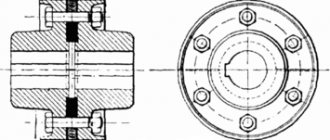
Active resistance in the rotor circuit
When using this method, a rheostat or a set of high-power constant resistors is connected to the rotor circuit. This device is designed to smoothly increase resistance.
Slip increases in proportion to the increase in resistance, and the rotation speed of the electric motor shaft decreases.
Asynchronous valve cascade and dual-fed machines
Changing the operating speed of asynchronous electric motors in these cases is done by changing the slip. In this case, the rotation speed of the electromagnetic field remains unchanged. Voltage is supplied directly to the stator windings. The adjustment occurs through the use of sliding power, which is transformed into the rotor circuit and forms an additional EMF. Such methods are used only in special machines and large industrial devices.
Completed projects
NPO "Vint", Moscow.
Thrusters for ship propulsion. Vessels equipped with them gain greater maneuverability when mooring, passing through narrow spaces, and trawling. The risk of ship collisions is significantly reduced. Unloading and loading times are reduced, saving time and money. Stroybezopasnost LLC, Tikhoretsk. Equipment for tower crane drives. This solution simplifies control, makes it possible to finely regulate the speed over a wide range, and results in the absence of inrush currents.
JSC "Tagmet", Taganrog. Roller conveyors of a slot hardening furnace. They ensure accurate pipe catching in the loading zone and separation at the outlet and trouble-free operation of the equipment. The main economic effect of using frequency converters is improving product quality.
OJSC "Ulyanovsk Sugar Factory", r.p. Tsilna, Ulyanovsk region. Press drive 500 kW. It regulates the speed according to the load: as a result, the chips are supplied unevenly and there are no transfers, while maintaining the desired level of pressure in the shaft. The service life of equipment is increased, the number of emergency stops is reduced, and process maintenance is simplified.
MUP "Vodokanal", Novocheboksarsk. Automated operational dispatch control system (ASODU) for water supply in Novocheboksarsk. In addition to reducing direct energy costs, the accident rate has decreased and the quality of service has improved.
Main types of single-phase electric drives
As mentioned, a single-phase motor cannot develop starting torque, which makes it impossible to start it independently. To do this, they came up with several ways to compensate for a magnetic field that is opposite in sign to the main one.
Motors with starting winding
In this starting method, in addition to the main winding P, which has a phase zone of 120, a starting winding P, which has a phase zone of 60, is also wound on the stator. Also, the starting winding is shifted relative to the working winding by 90 electrical. In order to create a phase shift between the winding currents Ip and Ip, an element leading to a phase shift ψ (phase-shifting resistance Zp) is connected in series to the starting winding:
Where: a) connection diagram of the machine, b) vector diagrams when using different resistances.
The best conditions for starting are to include a capacitor in the starting winding. But since the capacitor capacity is quite large, its cost and dimensions also increase accordingly. It is often used to obtain increased starting torque. Inductive starting has the worst performance and is not currently used. Quite often, starting with the help of active resistance can be used, while the starting winding is made with increased active resistance. After the electric motor starts, the starting winding is turned off. The connection diagrams and their starting characteristics are shown below:
Where: a, b) motors with a starting winding, c, d) capacitor motors
Capacitor motor
This type of electric motor has two working windings, one of which is connected to the working capacitance Cp. These windings are shifted relative to each other by 90 electrical and have phase zones also 90. In this case, the powers of both windings are equal, but their currents and voltages are different, and the number of turns is also different. Sometimes the size of the working capacitor is not enough to generate the required starting torque, so a starting one can be hung in parallel with it, as shown in the figure above. The diagram is shown below:
Where: a) circuit of a capacitor electric motor, b) its vector diagram
In this type of single-phase machines, the power factor cosφ is even higher than that of three-phase machines. This is due to the presence of a capacitor. The efficiency of such an electric motor is higher than that of a single-phase electric motor with a starting winding.
Dual mode regulators
The design of a two-mode automatic speed controller for the VE fuel pump and its operation in various modes are shown in the figures below, which have a general specification. The regulator shaft receives rotation from the injection pump shaft through a gear overdrive with a gear ratio of 1:1.6 and transmits it to a holder with four weights.
The VE fuel pumps with all-mode regulators discussed above have a similar design to this unit.
The amount of fuel supply changes when the position of the metering clutch 15 changes, which is determined by the balance of the centrifugal force of the loads applied to the clutch and the force from the action of the operating springs of the regulator, depending, in particular, on the position of the accelerator pedal.
The diesel start mode is shown in the figure. When the engine is not running, the regulator weights are brought together and clutch 19 is in the extreme left position. The corrector lever 16 and the starting lever 18 are pressed under the action of the starting feed spring 12 to the regulator coupling 19, turning relative to the M2 axis. Thus, the metering clutch 15 is moved by the lower hinge of the lever system to the right in the figure below, providing a starting feed. The accelerator pedal may remain in the unpressed position when starting the diesel engine. The amount of starting feed is determined by the active stroke ΔS1.
Rice. Diagram of a two-mode regulator. Diesel start mode: 1 — weight holder; 2 — regulator weights; 3 - earring; 4 — control lever axis; 5 - nominal mode spring; 6 — partial mode spring; 7 — maximum feed adjusting screw; 8 — damper spring; 9 — minimum mode idle spring; 10 — power lever; 11 — adjustment lever; 12 — starting feed spring; 13 — support spring; 14 — injection pump plunger; 15 - dosing coupling; 16 — negative corrector lever; 17 — negative corrector spring; 18 — starting lever; 19 — regulator coupling; 20 — regulator spring housing; 21 — feed cut-off holes; hinges of the lever system of the regulator: M1 - the lever system at this point is supported by two movable fingers installed in lever 2; M4 - common axis of the starting and corrector levers; ΔS1 is the stroke of the metering coupling.
After starting the engine, the regulator weights diverge under the action of centrifugal force and push the regulator coupling 19 to the right, overcoming the resistance of the starting feed spring 12. In this case, the head of the rod of the corrector lever 16 rests at point A on the power lever 10, and the M4 axis moves to the right on hinge A until until the force of the regulator clutch is equal to the force of the idle spring 9. Accordingly, the metering clutch 15 is moved by the M2 hinge to the left until the idle supply is established, which corresponds to the diagram in the figure.
Rice. Operation of the regulator at idle speed of the minimum mode
The figure shows the interaction of the regulator elements when the diesel engine is operating at partial speed modes, when the accelerator pedal is lightly pressed. The sequence with which the regulator springs come into operation is determined by their stiffness and preliminary deformation. The damper spring 8 works first, followed by the partial mode spring 6 and finally the nominal mode spring 5.
The control lever is connected to the accelerator pedal. When you press it, the damper spring 8 is compressed and the power lever is pulled to the left, as a result of which the metering clutch moves to the right, towards an increase in feed with a corresponding increase in rotation speed. The regulator clutch 19, due to the increase in the centrifugal force of the loads, presses on the corrector lever, which rests against the power lever at a point as a result of which the idle spring 9 is compressed as much as possible, and then the power lever, with two hinge points A and B, moves to the right, together with the axis M2. Under these conditions, when the power arm moves to the right and the spring body is moved to the left by the driver, the part-load spring is compressed until a balance of forces is achieved. When the load decreases and the rotation speed increases, the power lever will move under the action of the regulator clutch 19 to the right by the stroke ΔS2 of the spring 6, and the metering clutch 15 to the left, in the direction of decreasing the flow until the steady-state speed mode of the diesel engine is reached.
Rice. Controller operation in partial speed mode
Rice. Regulator operation at full load
The operation of the diesel regulator at full load is illustrated in the figure. In this case, the accelerator pedal is pressed until the control lever stops in the maximum mode adjusting screw. In this case, the power lever 10 is on the stop M3, and the starting, minimum idle 9, damper 8 and partial load springs 6 are in a fully compressed state. The regulator coupling 19 is in equilibrium under the action of oppositely directed centrifugal forces of weights and the pre-tightening force of the working spring 5. Fuel supply at full load mode is determined by the active stroke of the plunger, indicated by two arrows at the metering coupling 15. The two-mode regulator considered here is equipped with a negative fuel supply corrector. When the diesel engine is operating on the left branch of the external speed characteristic, at n < nm, the spring 17 of the negative corrector is unclenched and, through a system of levers, moves the metering clutch 15 in the direction of decreasing the flow, moving the external characteristic away from the smoke limit.
Rice. Negative corrector operation
The maximum idle speed mode and the formation of the corresponding regulatory characteristic occur when the load of the engine operating at full (nominal) power is reduced. In this case, the rotation speed of the engine shaft and the regulator weights increases, and the latter moves the clutch 19 to the right, which causes the regulator spring 5 to compress and thereby rotates the lever system clockwise relative to the M2 axis, reducing the fuel supply to the idle supply value. This process is shown in the figure.
If, when the load is completely removed, there is an uncontrolled increase in rotation speed, which is dangerous for the engine, the regulator completely stops the supply of fuel to the diesel cylinders. In this case, the regulator operates in accordance with the figure, only at a rotation speed higher than at the maximum idle speed mode. At the same time, the metering clutch moves even more to the left, completely opening the shut-off holes 21, as a result of which all the fuel from the high-pressure chamber of the injection pump returns to the internal cavity of the pump housing and fuel injection stops.
Rice. Operation of the regulator at idle speed of maximum mode
The graph of the fuel supply speed characteristics of the dual-mode regulator discussed above is shown in the figure; the purpose of the various curves on the characteristic is indicated by captions. The presence of a partial mode spring in the regulator allows for greater smoothness and stability of regulation at low loads and speeds. Otherwise, the characteristics of the two-mode controller discussed above are similar to the general characteristics.
Rice. Speed characteristics of the fuel supply of an injection pump with a two-mode regulator: a - starting supply, b - section of supply reduction after starting the diesel engine, c - stroke when compressing the partial mode spring, d - driver control area for supply, e - regulatory characteristics of the maximum mode
Frequency controller structure
All modern frequency converters are built on the principle of so-called double conversion. That is, alternating current is converted into direct current through an uncontrolled rectifier and filter. Next, through a pulse inverter (it is three-phase), the reverse conversion of direct current into alternating current occurs. The inverter itself consists of six power switches (transistor). So, each winding of the electric motor is connected to certain rectifier switches (positive or negative). It is the inverter that changes the frequency of the voltage that is applied to the stator windings. In fact, it is through it that the frequency regulation of the electric motor occurs.
In this device, power transistors are installed at the output. They act as keys. If we compare them with thyristors, it should be noted that the former produce a signal in the form of a sinusoid. It is this shape that creates minimal distortion.
All-mode regulators
Schemes of operation of the all-mode speed controller of the VE fuel pump with a system of levers and operating positions of the metering clutch at various load and speed modes are shown in Figures a, b, c, d.
Rice. Operation of an all-mode regulator: a - position at start-up; b — idling of the minimum mode; c — load reduction mode; d — load increase mode; 1 — regulator weights; 2 — regulator coupling, 3 — power lever; 4 — pressure lever, 5 — starting feed spring; 6 - dosing coupling; 7 - cut-off holes in the plunger; 8 - plunger; 9 — minimum idle speed adjustment screw; 10 — control lever; 11 — maximum mode adjusting screw; 12 — control lever axis; 13 — working spring of the regulator; 14 — spring retainer; 15 — minimum mode spring; 16 — stop of the power lever; M2 - axis of rotation of levers 4 and 5; h, and h2 active stroke of the plunger in various modes
Regulator weights 1 (usually four weights) are installed in a holder, which receives rotation from the drive gear. The radial movement of the loads is transformed into the axial movement of the regulator coupling 2, which changes the position of the pressure 4 and power 3 levers of the regulator, which rotate relative to the M2 axis. move the dosing coupling 6, thereby determining the active stroke of the plunger 8.
An idle spring 15 is installed in the upper part of the power lever, and between the power and pressure levers there is a plate spring of the starting feed 5. The control lever 10 acts on the operating spring of the regulator 13, the second end of which is fixed in the power lever on the latch 14. Thus. position of the lever system and. therefore, the metering clutch is determined by the interaction of two forces - the pre-tightening force of the working regulator spring, determined by the position of the control lever, and the centrifugal force of the loads driven to the clutch.
Operation of the regulator when starting a diesel engine
Before starting the diesel engine, when the crankshaft is not yet rotating and the fuel pump is not working, the regulator weights are at rest at the minimum radius, and the push lever 4 (its other name is the start lever) under the action of the starting feed spring 5 is shifted to the left in Figure a, having the ability to swing relative to the M2 axis. Accordingly, the lower hinged end of the lever ensures the extreme right position of the dispenser 6 relative to the plunger 8, which corresponds to the starting feed due to the increased active stroke of the plunger h1. As soon as the engine starts, the regulator weights diverge and clutch 2 moves to the right by the amount of stroke “a”, overcoming the resistance of a rather weak starting spring 5. Lever 4 rotates clockwise on the M2 axis, moving the metering clutch in the direction of decreasing feed (to the left by Fig. b).
Controller operation at minimum idle speed
When there is no load and the control lever is positioned against the stop in adjusting screw 9, the diesel engine should operate stably at a minimum idle speed in accordance with the diagram in Figure b. Regulation of this mode is ensured by the idle spring 15. The force of which is in equilibrium with the centrifugal force of the loads, and as a result of this equilibrium, the fuel supply is maintained, corresponding to the active stroke of the plunger h2. Diesel operation in this mode corresponds to point 5 in the characteristic of the first figure. As soon as the engine speed goes beyond the minimum idle speed, the “c” stroke of the power lever is realized when the spring 15 is compressed under the influence of the increasing centrifugal force of the loads.
Operation of the regulator under load conditions
In operation of a diesel engine with an all-mode regulator, the speed mode is set by the driver by acting through the accelerator pedal on control lever 10. In operating modes, the starting feed spring 5 and the idle spring 15 do not work, and the operation of the regulator is determined by the preliminary deformation of the operating spring 13. When turning the control lever to stop 11 (figures c, d) in the direction of increasing the speed mode and the corresponding stretching of the working spring, its force is transmitted to the power lever 3 and then through the lever 4 to the regulator clutch 2, forcing the loads 1 to converge. In this case, the lever system rotates relative to the M2 axis counterclockwise in the figure, moving the metering clutch 6 in the direction of increasing the feed to the external speed characteristic modes. The rotation frequency of the diesel crankshaft and, accordingly, the regulator loads increases, the centrifugal force of the loads and the resistance of the latter to the force of the working spring also increase, and at some point a balance of forces and an equilibrium of position of all elements of the regulator occurs. In the absence of load changes, the engine operates at a steady state at a constant speed (without taking into account the rotation instability natural to the LAN).
If in this mode there is a change in the load, then the automatic regulator comes into operation in accordance with the diagrams shown in figures c, d. When the load decreases, the rotation speed increases, the regulator weights diverge and, overcoming the resistance of the working spring, move the regulator coupling to the right (figure V). In this case, the lever system rotates relative to the M2 axis clockwise, moving the metering clutch to the left, in the direction of decreasing feed. As a result, regulatory branch 4 in the first figure is formed. If the control lever is installed in some intermediate position, then, in comparison with the regulator setting shown in figures c, d, one of the regulatory characteristics shown by the dotted line in the first figure b will be formed, i.e. in the latter case, the regulator starts working earlier - at a lower rotation speed.
Figure d shows the operation of the regulator when the control lever is positioned on stop 11 and when the load increases. In this case, the rotational speed of the diesel shaft decreases, the governor weights converge, the centrifugal force of the weights decreases, and under the force of the working spring, the governor clutch moves to the left, and the system of levers 3 and 4 moves the metering clutch to the right, in the direction of increasing feed. If the diesel engine was working on the regulatory branch before the load began to increase, then with an increase in the supply it will reach a higher power mode and then the external speed characteristic. If the diesel engine operates on the external characteristic at the nominal or close to it mode, then when the load increases, an overload mode is realized, to overcome which the diesel engine must have a sufficiently high adaptability coefficient. Positive correction of the fuel supply is carried out in section 3 of the characteristic using a positive corrector or with the appropriate selection of the fuel supply characteristics of the injection pump.
Fuel correctors
Correction of the fuel supply in diesel engines, positive or negative, is carried out in order to form the external speed characteristics of the engine if it is necessary to increase the maximum torque by increasing the supply when reducing the rotation speed from nnom to nm in the so-called overload mode (positive correction) or to reduce diesel smoke when operating at n < nm according to the external speed characteristic. The effect of the correction on the external speed characteristics of the diesel engine is shown in the figure below. Positive correction is necessary to ensure a given reserve of engine torque.
Rice. External characteristics of the diesel engine: Me - torque, n - rotation speed, nm - rotation speed at maximum Me, nnom - nominal mode rotation speed, n min - minimum rotation speed according to the external characteristic
Correction of the characteristic can be carried out using the injection valve of the injection pump or a mechanical corrector in the regulator. With the help of a mechanical corrector, negative correction is also carried out. The latter is usually used in engines to reduce soot emissions at n < nm1, as well as in turbocharged engines and high-pressure fuel injection pumps without a boost pressure corrector, i.e. without feed limitation in LDA system.
Operation of positive and negative correctors
The design and operation of the positive and negative mechanical fuel supply correctors of the VE fuel pump is illustrated in Fig. a, b.
Rice. Diagram of a regulator with a positive (a) and negative (b) fuel supply corrector: 1 - starting lever; 2 — corrector springs; 3 — working spring of the regulator; 4 — power lever 5 — stop; 6 — corrector levers; 7 — corrector rod; 8 - dosing coupling; 9 — starting feed spring; 10 — regulator coupling; 11 — stop point; Mg - axis of rotation of levers 1 and 4; M4 - axis of rotation of levers 1 and 6; ΔS—feed correction stroke
The onset of action of the direct (positive) fuel supply corrector is determined by the stiffness and pre-compression of its spring, which are coordinated with the corresponding speed mode of the diesel engine. The positive corrector works as follows. In the nominal mode, the metering clutch 8 occupies the position indicated by the dotted line in Fig. A. The corrector spring 2 is compressed due to the influence of the centrifugal force of the loads through the clutch 10 of the regulator on the lever 6, which presses on the head of the rod 7, turning on the stop 5 in the power lever 4. Lever 1 is rotated clockwise and the dispenser provides a cyclic feed , which meets the requirements of the nominal diesel mode (see dotted line in Fig. a). If the load in this mode increases (overload mode), the rotation speed decreases, the force on the side of the regulator clutch also decreases, and the corrector spring 2 through lever 6 turns lever 1 counterclockwise, moving the metering clutch to the right, in the direction of increasing the feed by the amount ΔS ( Fig. a).
Negative corrector operation
When working with the minimum frequency on the external characteristic, lever 6 of the corrector rests on the power lever at point 5 (Fig. b). The head of the corrector rod 7 also rests against the power lever 4. As the rotation speed increases, the centrifugal force of the loads applied to the clutch overcomes the force of the corrector spring 2, compressing it. as a result, lever 6 moves to the right in the figure, towards the head of the rod, while the common axis of the levers M4 changes its position. At the same time, lever 1 rotates relative to the M2 axis, moving the metering clutch 8 in the direction of increasing the feed. The course of correction ΔS is determined by the compression stroke of the corrector spring until lever 6 stops against the head of rod 7. When the diesel engine is running on the left side of the external speed characteristic, with an increase in load and a decrease in rotation speed, spring 2 turns lever 6 clockwise, and the latter causes lever 1 to rotate relative to the axis M2 clockwise, moving the metering clutch 8 in the direction of decreasing feed, thus performing a negative correction (area nmin < n < nm in the figure).
VFD Application Industries
The list of industries is extensive; it is more difficult to find an industry where emergency situations are not applied:
Oil production and refining
: pumping equipment, drive of air cooling units (ACU) and cooling towers, comprehensive automation of various technological lines.
Metallurgy
: drives of roller tables, conveyors, rolling mills, winding devices of drawing mills, pumps, fans.
Mechanical engineering
: drive of processing machines, pumps, conveyor lines, printing machines.
Mining and processing production
: crushers, mixers, conveyors, sand and pulp pumps.
Chemical industry
: pumps, mixers, granulators, extruders, centrifuges, smoke exhaust and fan drives, automated control systems.
Food industry
: granulators, extruders, mills, crushers, cutters, pulp presses, labeling machines, conveyors, production lines, pumps, fans.
Housing and communal services
: various pumping equipment, automated control systems.
Construction complex
: cranes, lifting mechanisms.
Transport
: ship drive, electric transport.
Vector feedback control
Feedback vector control uses the same control algorithm as open-loop VAC. The main difference is the presence of an encoder, which allows the variable frequency drive to develop 200% starting torque at 0 rpm. This point is simply necessary to create an initial moment when moving off elevators, cranes and other lifting machines, in order to prevent subsidence of the load.
The presence of a speed feedback sensor allows you to increase the system response time to more than 50 Hz, as well as expand the speed control range to 1:1500. Also, the presence of feedback allows you to control not the speed of the electric machine, but the torque
In some mechanisms, it is the torque value that is of great importance. For example, winding machine, capping mechanisms and others
In such devices it is necessary to regulate the torque of the machine.