The battery is a faithful friend and assistant in the most difficult situations, but, unfortunately, it does not last forever. It would be okay if the battery died instantly, without hope of recovery. But it gradually loses its characteristics, so it often turns out that it is simply impossible to turn the starter. The peak of battery failure occurs in winter, when it is especially difficult for equipment to start in cold weather. And then either a neighbor in the garage comes to the rescue with wires for lighting, or a spare battery. Or a good starting device, which every thrifty car enthusiast has.
Types of starting devices
Having some skills in radio electronics, we assemble a starting device for a car with our own hands. We will show drawings and photos, but first we will decide on its type, since they are different. Regardless of the type, it is important for us, as users, that the PU can work without the help of a battery and starts the engine not at the limit of its capabilities, turning red and smoking, but working stably even in severe frost. This is the most important condition when choosing a ready-made charging and starting device or assembling it yourself.
There is no special pickle here. The mechanism can be one of four types:
- pulse;
- transformer;
- battery;
- capacitor.
The essence of the work of each of them ultimately comes down to supplying the on-board electrical network with a current of the required rating and voltage, 12 or 24 volts, depending on the type of electrical equipment on board.
Classification of starter-chargers
Despite similar functions for starting internal combustion engines, ROMs come in several types in terms of design and mechanism. Types of ROM:
- transformer;
- battery;
- capacitor;
- pulsed.
There are also factory models, among which you need to choose ROMs that start without a battery and work stably even in severe frost.
The output of each of them produces a current of a certain value and a voltage (U) of 12 or 24 V (depending on the device model).
Transformer ROMs are the most popular due to their reliability and repairability. However, among other types there are worthy models.
Transformer type
The operating principle of transformer ROMs is very simple. The transformer converts the mains U into a reduced variable, which is rectified by a diode bridge. After the diode bridge, the direct current with pulsating amplitude components is smoothed out by a capacitor filter. After the filter, the current rating is increased using various types of amplifiers made of transistors, thyristors and other elements. The main advantages of transformer type ROM are the following:
- reliability;
- high power;
- starting the car if the battery is “dead”;
- simple device;
- regulation of U values and current strength (I).
The disadvantages are its dimensions and weight. If you can’t buy one, then you need to assemble a starting charger for the car with your own hands. The transformer type has a fairly simple device (diagram 1).
Scheme 1 - Homemade starting device for a car.
To make a starter-charger with your own hands, the circuit of which includes a transformer and a rectifier, you need to find radio components or purchase them at a specialized store. Basic requirements for a transformer:
- power (P): 1.3−1.6 kW;
- U = 12−24 V (depending on the vehicle);
- winding current II: 100−200 A (the starter consumes about 100 A when rotating the crankshaft);
- area (S) of the magnetic circuit: 37 sq. cm;
- wire diameters of windings I and II: 2 and 10 sq. mm;
- the number of turns of winding II is selected during calculation.
Diodes are selected according to reference literature. They must be designed for large I and reverse U > 50 V (D161-D250).
If it is not possible to find a powerful transformer, then the circuit of a simple car starting-charging device will have to be complicated by adding an amplifier stage using a thyristor and transistors (scheme 2).
Scheme 2 - Do-it-yourself starting and charging with a power amplifier.
The principle of operation of a ROM with an amplifier is quite simple. It must be connected to the battery terminals. If the battery charge is normal, then U does not come from the ROM. However, if the battery is discharged, then the thyristor junction opens and the electrical equipment is powered by the ROM. If U increases to 12/24 V, then the thyristors close (the device turns off). There are two types of thyristor transformer ROMs:
- full-wave;
- pavement.
This is interesting: Tuning Mercedes Gelendvagen with photo
With a full-wave manufacturing circuit, you need to choose a thyristor of about 80 A, and with a bridge circuit, from 160 A and above. Diodes must be selected taking into account a current from 100 to 200 A. The KT3107 transistor can be replaced with a KT361 or another analogue with the same characteristics (it can be more powerful). Resistors located in the thyristor control circuit must have a power of at least 1 W.
Boosters and capacitors
Battery-type ROMs are called boosters and represent portable batteries that operate on the principle of a portable charger unit. They are domestic and professional. The main difference is the number of built-in batteries. Household ones have a capacity sufficient to start a car with a dead battery. It can only power one unit of equipment. Professional ones have a large capacity and are used to start not one car, but several.
Capacitors have a very complex design, and, therefore, it is unprofitable to make them yourself. The main part of the circuit is the capacitor block. Such models are expensive, but they are portable ROM, capable of starting the starter even with a “dead” battery. Frequent use causes the battery to wear out very quickly if it is new. The most popular among all models were Berkut (Figure 1) with starting currents of 300, 360, 820 A. The operating principle of the device is to quickly discharge the capacitor unit and this time is enough to start the internal combustion engine.
If you compare battery and capacitor ROM, you need to take into account the features of use in a specific situation. For example, when traveling around the city, the battery type is suitable. In the event that long trips occur, then you should choose an autonomous type of ROM, namely capacitor.
Transformer control panel, parameters
Transformer PUs are popular among DIYers. There is probably no need to explain the principle of their operation - it is a transformer that converts network electricity to the required parameters. These devices have one disadvantage - their enormous size and weight. But they are reliable and change the output parameters of voltage and current as needed. They are quite powerful and start the engine even with a dead battery. The simplest drawing for a transformer-based starter is shown below.
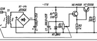
Schematic diagram
The starting charger circuit contains a triac voltage regulator (VS1), a power transformer (T1), a rectifier with powerful diodes (VD3, VD4) and a starter battery (GB1). The charging current is selected by the current regulator on the triac VS1, its current is regulated by the variable resistor R2 and depends on the battery capacity.
The input and output charging circuits have filter capacitors, which reduce the degree of radio interference during operation of the triac regulator. Triac VS1 provides regulation of the charging current when the network voltage varies from 180 to 220 V.
Transistor tester / ESR meter / generator
Multifunctional device for testing transistors, diodes, thyristors...
More details
The triac wiring consists of R1-R2-C3 (RC circuit), dinistor VD2 and diode bridge VD1. The time constant of the RC circuit affects the opening moment of the dinistor (counting from the beginning of the network half-cycle), which is included in the diagonal of the rectifier bridge through the limiting resistor R4. The rectifier bridge synchronizes the switching on of the triac in both half-cycles of the mains voltage. In the “Regeneration” mode, only one half-cycle of the mains voltage is applied, which helps clean the battery plates from existing crystallization. Capacitors C1 and C2 reduce the degree of interference from the triac in the network to acceptable levels.
How to choose a transformer
To make the device yourself, it is enough to find a suitable transformer, and for a reliable start it must produce at least 100 A and a voltage of 12 V, if we are talking about a passenger car. If you ask a fifth grader, he will be able to calculate the power. In our case, it is 1.2, or better yet 1.4 kW. Without a battery, it will hardly be possible to start the engine with such current, because the starter needs at least 200 A. A standard battery will help spin the crankshaft, and while rotating, the starter consumes no more than 100 A, which is what our device will produce.
The core area cannot be less than 37 cm², and the primary winding wire must be at least 2 mm². The secondary is wound with copper wire with a cross-section of 10 squares, and the number of turns is selected experimentally so that the open circuit voltage is no more than 13.9V.
Details
The charger and starting device uses a power transformer from the Rubin TV. It is also possible to use a TCA-270 type transformer. Before rewinding the secondary windings (the primary windings remain unchanged), the frames are separated from the iron, all former secondary windings (up to the screen foil) are removed, and the free space is wound with copper wire with a cross-section of 1.8...2.0 mm2 in one layer (up to filling) secondary windings. As a result of rewinding, the voltage of one winding should be approximately 15 ... 17 V.
To visually monitor the charging and starting current, an ammeter with a shunt resistor is introduced into the circuit of the charging and starting device. Network switch SA1 must be designed for a maximum current of 10 A. Network switch SA2 (type TZ or P1T) allows you to select the maximum voltage on the transformer in accordance with the network voltage. The internal battery of the 6ST45 or 6ST50 brand should be enough for 3-5 simultaneous starts. Resistors in the ZPU can be used like MLT or SP, capacitors C1, C2 - KBG-MP, C3 - MBGO, C4 - K50-12, K50-6. The D160 diodes (without radiators) can be replaced with others with a permissible current of more than 50 A, the triac is of the TC type. The connection of the charger to the car battery must be made using powerful “Crocodile” clamps (for operating current up to 200 A). It is important to use grounding in the device.
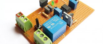
Diagram and details of PU assembly
Calculating the parameters of a transformer is not all. The device works like this. We connect the power wires directly to the battery terminals, while there is no voltage at the output of the control unit until the battery voltage drops below the response threshold of the thyristors, which are indicated in the diagram. As soon as the voltage at the battery terminals drops, the thyristors open the input and only then the electrical equipment is powered by the device. As soon as the voltage at the battery terminals rises to 12 V, the thyristors close and the device automatically turns off. This allows you to save the battery from overload.
The thyristor version can be assembled using two methods - using a full-wave circuit and using a bridge circuit. If the rectifier is a bridge rectifier, then the thyristors must be selected twice as powerful. That is, according to the first scheme, thyristors are rated at a minimum of 80 A, and with a bridge circuit - at least 160 A. Diodes are rated for a current of at least 100 A. These elements are easily recognized by their braided output tip. The KT3107 transistor can be replaced with the 361st. There is only one requirement for resistance in the control circuit - their power must be at least one Watt.
The output wires, naturally, must correspond to the current and, as a rule, for this they take an analogue from a welding machine. Naturally, they are no thinner than the secondary wire. The wire that connects the network has a cross-section of each core of at least 2.5 square millimeters. A simple and reliable assembly that will start the engine in any frost. However, there are other options that you can buy in the store.
Starting device for cars, diagram
Winter, frost, the car won’t start, while we tried to start it, the battery is completely discharged, we are scratching our heads, thinking about how to solve the problem... Is this a familiar situation? I think those who live in the northern regions of our vast country have more than once encountered problems with their car in the cold season. And then such a case arises, we begin to think, it would be nice to have on hand a starting device designed specifically for such purposes.
Naturally, buying such an industrially produced device is not a cheap pleasure, so the purpose of this article is to provide you with information on how you can make a starting device with your own hands at minimal cost.
The starting device circuit that we want to offer you is simple but reliable, see Figure 1.
This device is designed to start the engine of a vehicle with a 12 volt on-board network. The main element of the circuit is a powerful step-down transformer. The bold lines in the diagram indicate the power circuits going from the starter to the battery terminals.
At the output of the secondary winding of the transformer there are two thyristors, which are controlled by a voltage control unit. The control unit is assembled on three transistors; the response threshold is determined by the value of the zener diode and two resistors forming a voltage divider.
The device works as follows. After connecting the power wires to the battery terminals and turning on the mains, no voltage is supplied to the battery. We begin to start the engine, and if U of the battery drops below the operating threshold of the voltage control unit (this is below 10 volts), it will give a signal to open the thyristors, the battery will receive recharge from the starting device.
When the voltage at the terminals reaches above 10 volts, the starting device will disable the thyristors and recharge the battery will stop. As the author of this design says, this method avoids harming the car battery.
Transformer for starting device.
In order to estimate how much power a transformer is needed for a starting device, you need to take into account that at the moment the starter starts, it consumes a current of about 200 amperes, and when it spins up, it consumes 80-100 amperes (voltage 12 - 14 volts). Since the starting device is connected directly to the battery terminals, when the car starts, some of the electricity will be supplied by the battery itself, and some will come from the starting device. We multiply the current by the voltage (100 x 14), we get a power of 1400 watts. Although the author of the above diagram claims that a 500-watt transformer is enough to start a car with a 12-volt on-board network.
In the original design, a transformer with an overall power of 500 watts was used, the cross-section of the wire of winding II was 14 square meters. mm (this is a wire folded in half with a diameter of 3 mm). Output voltage 15…18 volts.
Just in case, let us recall the formula for the ratio of wire diameter to cross-sectional area, this is the diameter squared multiplied by 0.7854. That is, two wires with a diameter of 3 mm will give (3*3*0.7854*2) 14.1372 sq. mm .
It doesn’t make much sense to provide specific data on the transformer in this article, because first you need to at least have more or less suitable transformer hardware, and then, based on the actual dimensions, calculate the winding data specifically for it.
The remaining elements of the scheme.
Thyristors:
with a full-wave circuit - for a current of 80A and above. For example: TS80, T15-80, T151-80, T242-80, T15-100, TS125, T161-125, etc. When implementing the second option using a bridge rectifier (see diagram above), the thyristors must be 2 times more powerful. For example: T15-160, T161-160, TS161-160, T160, T123-200, T200, T15-250, T16-250 and the like.
Diodes:
for the bridge, choose ones that hold a current of about 100 amperes. For example: D141-100, 2D141-100, 2D151-125, V200 and the like. As a rule, the anode of such diodes is made in the form of a thick rope with a tip. KD105 diodes can be replaced with KD209, D226, KD202, any with a current of at least 0.3 ampere will do. The stabilization zener diode U should have about 8 volts, you can use 2S182, 2S482A, KS182, D808.
Transistors:
KT3107 can be replaced with KT361 with a gain (h21e) greater than 100, KT816 can be replaced with KT814.
Resistors:
In the circuit of the thyristor control electrode we place resistors with a power of 1 watt, the rest are not critical.
If you decide to make the power wires removable, ensure that the connection connector can withstand inrush currents. Alternatively, you can use connectors from a welding transformer or inverter.
The cross-section of the connecting wires coming from the transformer and thyristors to the terminals must be no less than the cross-section of the wire with which the secondary winding of the transformer is wound. It is advisable to install the wire connecting the starting device to a 220 volt network with a core cross-section of 2.5 square meters. mm.
In order for this starting device to work with cars whose on-board network has a voltage of 24 volts, the secondary winding of the step-down transformer must be designed for a voltage of 28...32 volts. The zener diode in the voltage control unit must also be replaced, i.e. D814A must be replaced with two D814V or D810 connected in series. Other zener diodes are also suitable, for example, KS510, 2S510A or 2S210A.
Pulse charger starting device
A pulse device is an excellent option when you need to constantly monitor your battery and keep it in working condition. Such designs operate on the principle of pulsed current conversion, and they are assembled on microprocessors and controllers. It cannot show much power, so it may not be suitable for starting, especially at severe subzero temperatures, but it is excellent for charging batteries.
They are compact, low in price, weigh very little and look nice. But the low power, or rather the low starting current that they produce, will not allow you to start the car with heavily discharged banks in the cold. In addition, precision electronics do not tolerate voltage surges and current frequency surges, which are not uncommon in our networks, and if something happens, not even every workshop can repair such a device.
Jump Charger
Starting a car engine in winter with a discharged battery takes a long time. The density of the electrolyte after long-term storage decreases significantly; the occurrence of coarse-crystalline sulfation increases the internal resistance of the battery, reducing its starting current. In the winter season, the viscosity of engine oil increases, which requires more starting power from the starting current source.
There are several ways out of this unpleasant situation: 1) heating the oil in the crankcase; 2) the ability to “light” from another car or start from a pusher; 3) use of a starting charger.
The latter option is more preferable when storing cars in a paid parking lot; such a device will not only allow you to start the car, but also quickly restore and charge more than one battery during breaks.
The difference from factory starting chargers is that in the factory starting internal battery is recharged from a low-power power supply with a current of up to 3-5 amperes, which is not enough to take power to the car starter, also in the factory device the power of the internal starter batteries is increased exorbitantly to 240 a/h and after several starts it is impossible to quickly restore their capacity. The weight of such a block on wheels exceeds 200 kg; it is not always possible for two people to even roll it to the car. I once had to repair such a box in the laboratory; even with the batteries removed, the weight of the launch cart is quite high.
The charger recovery device proposed by our laboratory differs from the factory prototype in its light weight, almost five times lower, with the same starting current, and has the ability to automatically maintain the operating condition of the battery regardless of the storage time and time of use using the regeneration mode.
In the possible absence of an internal battery, the starting charger is capable of briefly delivering starting current of up to one hundred amperes.
The process of restoring the capacity of the internal battery after starting the car engine occurs intensively, in the absence of heating and boiling of the electrolyte.
Comparison table:
| № | Parameter | Magnitude | Jump Charger | ROM - 1 |
| 1 | Voltage | Volt | 12 | 12/24 |
| 2 | Starting current | Ampere | 200 | 300 |
| 3 | Capacity recovery time | minutes | 20-30 | 1-3 hours |
| 4 | Weight | kg | Less than 40 | More than 200 |
The buffer charging current is set by the current regulator R2 on the triac VS1 (Fig. 1). If there are large changes in the mains voltage, it is possible to select the mains voltage by switching toggle switch SA2 220-240 Volts.
The regeneration mode is an alternation of charge and discharge currents of equal time, speeds up the recovery of the plates and reduces the temperature of the electrolyte.
The charge current regulator R2 allows you to set the charging current depending on the battery capacity. The “Starting Charger” circuit consists of a triac voltage regulator, a power transformer T1, a rectifier with powerful diodes VD3, VD4 and a starter battery GB1.
Characteristics: Mains voltage 220-240 Volts Charge voltage 12 -18 Volts Charge current 5-10 Amps Starting current 30-50 Amps Charging time 1-3 hours Regeneration time 5-8 hours Device weight with starting battery - 40 kg
The input and output circuits of the device circuit contain filter capacitors C1C2, which reduce the level of interference during the operation of the triac regulator.
The switching angle regulator consists of an RC circuit R1, R2, C3 which allows you to set the switching time of the threshold dinistor VD2, connected to the diagonal of the diode bridge VD1 through the limiting resistor R4. The bridge allows you to synchronize the activation of triac VS1.
Power transformer T1 is used from a Rubin TS-320 color TV with copper windings; it can also be used with aluminum windings of the TSA-270 type; the winding terminals are the same in both versions. Before winding the secondary windings (the primary windings remain unchanged), the two frames should be separated from the iron, all secondary windings should be removed up to the screen foil and the free space should be tightly wound into one layer of winding with copper wire with a cross-section of 2-4 mm2. before filling, the voltage of one winding will be from 15 to 17 volts alternating current. The junction of the two windings (5,7) is connected to the minus bus of the battery power supply, the free terminals (6, 8) to the SA 4 switch and to the VD 4 diode.
In the “Regeneration” mode, one positive half-cycle of the current is used, which makes it possible to clean the battery plates from crystallization. To control the charging and starting current, a shunt with a device for a maximum current of 50 Amperes is installed in the positive bus circuit.
Indication LEDs HL1, HL2 indicate the presence of voltage in the primary and secondary circuits.
The SA1 mains switch is set to a current of up to 10 amperes; it can be replaced by an automatic switch with two lines for the same current. The mains voltage switch SA2 type T3 or P1T allows you to set the maximum voltage on the transformer in accordance with the mains voltage.
The internal battery GB1 is connected to the positive bus through a removable jumper P1. For 2-3 starts, it is enough to install a 6ST 45 or 6ST50 battery.
Connections of secondary circuits must be made with a copper busbar with a cross-section of at least 16 mm2. Connect to the car battery using crocodile clips for an operating current of up to 200 A.
The primary circuit is supplied with a three-core cable of sufficient length in cold-resistant vinyl insulation for a current of up to ten amperes; a grounding terminal in the socket is required.
The radio components in the circuit are not in short supply: MLT or SP type resistors, TS type triac, KBG-MP capacitors with three terminals (C1, C2), MBGO-C3, electrolytes K50-12, K50-6-C4.
D160 diodes, without radiators, can be replaced with any with a current of at least 50 Amperes. The starting charger is assembled in a separate case with dimensions 360 * 220 * 260 mm, mounted, the starting battery is installed on the platform, the cable connections to terminals X3, X4 are removable.
Connections in the primary circuit are made with a stranded wire with a cross-section of 2 mm square; all radio components, except those installed on the front panel of the device body, are mounted on a textolite platform without a metal coating 2 mm thick.
First connect the internal battery GB1 to the assembled device in the correct polarity, set the charging current using the current regulator R2, check the charging current in the charging, starting and regeneration modes; if it does not exceed 10 amperes, then the starting charger is working normally.
When connecting the device to a car battery, the current should increase 2-3 times; after 10-20 minutes it will drop to its original value due to pre-charging of the batteries. When such conditions are reached, switch SA3 should be switched to the “Start” mode and start the car engine; if the start is unsuccessful, carry out additional recharging for the same time and try again. If the start is successful, turn off the SA1 network, remove the XT3, XT4 clamps from the car battery, starting with the positive one, and secure them to an insulated stand to eliminate accidental short circuits.
Switch the internal battery using switch SA4 to regeneration mode with current setting using regulator R2 “Current setting” within 0.02 C, where C is the battery capacity GB1.
A similar device has been used in batteries since 1995 to charge and restore batteries, and, if necessary, used to start car engines in the winter.
Literature: 1. V. Konovalov, A. Razgildeev. Battery restoration. Radiomir No. 3. 2005 pp. 7-9. 2. V. Konovalov. Measurement R int "AB". Radiomir No. 11. 2005 Pages 14-15. 3. V. Konovalov. Charger and recovery device for Ni-Ca batteries. Radio No. 3. 2006. Pp. 53-54.
List of radioelements
| Designation | Type | Denomination | Quantity | Note | Shop | My notepad |
| VD1 | Diode bridge | KTs405B | 1 | Search in the Otron store | To notepad | |
| VD2 | Thyristor & Triac | KN102A | 1 | Search in the Otron store | To notepad | |
| VD3,VD4 | Diode | D106 | 1 | Search in the Otron store | To notepad | |
| VS1 | Thyristor & Triac | TS106-10-6 | 1 | Search in the Otron store | To notepad | |
| HL1 | Light-emitting diode | AL307B | 1 | Search in the Otron store | To notepad | |
| HL2 | Light-emitting diode | AL307V | 1 | Search in the Otron store | To notepad | |
| C1, C2 | Capacitor | 0.1uF 630V | 2 | Search in the Otron store | To notepad | |
| C3 | Capacitor | 0.5uF 250V | 1 | Search in the Otron store | To notepad | |
| C4 | Electrolytic capacitor | 100uF 50V | 1 | Search in the Otron store | To notepad | |
| R1 | Resistor | 33 kOhm | 1 | 1 W | Search in the Otron store | To notepad |
| R2 | Variable resistor | 100 kOhm | 1 | Search in the Otron store | To notepad | |
| R3 | Resistor | 75 kOhm | 1 | Search in the Otron store | To notepad | |
| R4 | Resistor | 100 Ohm | 1 | 0.5 W | Search in the Otron store | To notepad |
| R5 | Resistor | 1.5 kOhm | 1 | Search in the Otron store | To notepad | |
| T1 | Transformer | TC-320 | 1 | TCA-270 | Search in the Otron store | To notepad |
| FU1, FU2 | Fuse | 6A | 1 | Search in the Otron store | To notepad | |
| PA1 | Ammeter | 100A | 1 | Search in the Otron store | To notepad | |
| Shunt 75mV | 1 | Search in the Otron store | To notepad | |||
| Add all | ||||||
Mobile control units
Another type of PU, or rather two at once, similar in principle of operation - battery and capacitor. A capacitor device works by discharging charged capacitors upon command. Their composition cannot be called particularly complex, but capacitors of such ratings themselves are quite expensive and cannot be restored after damage or drying out. They are used very rarely, although they are quite mobile, but due to high unregulated currents there is a risk of harming the battery.
Boosters, or battery starters, work even simpler. By and large, this is just an additional battery in a self-contained case. It was their autonomy that brought them popularity. They can be used even in the steppe, where there is no electricity. The pre-charged battery is connected to the on-board power supply and quietly starts the engine. In this case, it is important to choose the booster capacity and its starting current. It cannot be less than that of a standard battery. Household autonomous units have a capacity of 18 A/h, while more expensive and bulky, professional devices can have a capacity of about 200 A/h.
Any of these driver assistants will help start the engine, but there is nothing more reliable and cheaper than a transformer PU assembled by yourself. Good luck to everyone and have a quick start!