04/27/201606/26/2016 master
For radio amateurs, and modern people in general, an indispensable thing in the house is a power supply unit (PSU), because it has a very useful function - voltage and current regulation.
At the same time, few people know that it is quite possible to make such a device with due diligence and knowledge of radio electronics with your own hands. For any radio amateur who likes to tinker with electronics at home, homemade laboratory power supplies will allow him to practice his hobby without restrictions. Our article will tell you how to make an adjustable power supply with your own hands.
What you need to know
A power supply with current and voltage regulation is a must-have item in a modern home. This device, thanks to its special device, can convert the voltage and current available in the network to the level that a particular electronic device can consume. Here is an approximate scheme of work according to which you can make such a device with your own hands.
Scheme
But ready-made power supplies are quite expensive to buy for specific needs. Therefore, today very often converters for voltage and current are made by hand.
Note! Homemade laboratory power supplies can have different dimensions, power ratings and other characteristics. It all depends on what kind of converter you need and for what purpose.
Professionals can easily make a powerful power supply, while beginners and amateurs can start with a simple type of device. In this case, depending on the complexity, a very different scheme can be used.
↑ Design and details
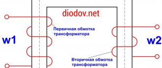
The output transformer
(W10x13, window H - 19 mm, window width 7 mm) was disassembled and rewound.
Was shot:
20 vit 0.75 mm 2x4 vit 0.9 mm 2x3 vit 0.72 mm 2x3 vit 0.72 mm
Wound:
170 vit 0.35 mm 20 vit 0.75 mm
Throttle
L1 (D - 23 mm) (also rewound). All windings were removed and a winding of 600 turns of 0.25 mm wire was wound, at the rate of 2 vit per volt of output voltage. The resulting inductance of the inductor was 29.62 mH.
Output bridge
assembled using UF4007 high-voltage diodes. Another UF4007 diode is installed at the bridge output to provide continuous current through the inductor and facilitate switching of the bridge diodes.
The fan is mounted in reverse - now it will pump cold air inside the power supply: onto the radiator and transformer.
To measure current and voltage, a voltmeter-ammeter is used on a PIC16F690 microcircuit
with scales for a voltmeter up to 400 Volts and for measuring current with a scale up to 600 milliamps. The circuit, board and program are located in the “Files” section. My datagor article on the topic: “AC Voltmeter-Ammeter with Power Calculation on PIC16F690.”
Structurally, all elements are housed in the ATX block housing. The radiator with diodes has been removed since the bridge diodes do not need it. The network connectors have been removed and a switch and output sockets have been installed in their place. On the side of the block cover there are resistors for setting voltage and current and a voltmeter-ammeter indicator. They are fixed to the false panel on the inside of the lid.
What to consider
Details
The regulated power supply is a universal converter that can be used to connect any household or computing equipment. Without it, not a single home appliance will be able to function normally. Such a power supply consists of the following components:
- transformer;
- converter;
- indicator (voltmeter and ammeter).
- transistors and other parts necessary to create a high-quality electrical network.
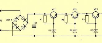
The diagram above shows all the components of the device. In addition, this type of power supply must have protection for high and low current. Otherwise, any emergency situation may lead to the fact that the converter and the electrical device connected to it simply burn out. This result can also be caused by improper soldering of board components, incorrect connection or installation. If you are a beginner, then in order to make an adjustable type of power supply with your own hands, it is better to choose a simple assembly option. One of the simple types of converter is a 0-15V power supply. It has protection against excess current in the connected load. The diagram for its assembly is located below.
Simple assembly diagram
This is, so to speak, a universal type of assembly. The diagram here is easy to understand for anyone who has held a soldering iron at least once in their hands. The advantages of this scheme include the following points:
- it consists of simple and affordable parts that can be found either on the radio market or in specialized radio electronics stores;
- simple type of assembly and further configuration;
- here the lower limit for voltage is 0.05 volts;
- dual-range protection for current indicator (at 0.05 and 1A);
- wide range for output voltages;
- high stability in the functioning of the converter.
Diode bridge
In this situation, the transformer will provide a voltage that is 3V higher than the maximum required output voltage. It follows from this that a power supply capable of regulating voltage up to 20V requires a transformer of at least 23 V.
Note! The diode bridge should be selected based on the maximum current, which will be limited by the available protection.
A 4700 µF filter capacitor will allow equipment sensitive to power supply noise to avoid background noise. To do this, you will need a compensation stabilizer that has a suppression coefficient for ripples of more than 1000. Now that we have dealt with the main aspects of the assembly, we need to pay attention to the requirements.
Device requirements
To create a simple, but at the same time high-quality and powerful power supply with the ability to regulate voltage and current with your own hands, you need to know what requirements exist for this type of converter. These technical requirements look like this:
- adjustable stabilized output for 3–24 V. In this case, the current load must be at least 2 A;
- unregulated 12/24 V output. This assumes a large current load.
To fulfill the first requirement, you should use an integral stabilizer. In the second case, the output must be made after the diode bridge, so to speak, bypassing the stabilizer.
Let's start assembling
Transformer TS-150–1
Once you have determined the requirements that your permanent regulated power supply must meet, and the appropriate circuit has been selected, you can begin the assembly itself. But first of all, let's stock up on the parts we need. For assembly you will need:
- powerful transformer. For example, TS-150–1. It is capable of delivering voltages of 12 and 24 V;
- capacitor. You can use a 10000 µF 50 V model;
- chip for stabilizer;
- strapping;
- details of the circuit (in our case, the circuit shown above).
After this, according to the diagram, we assemble an adjustable power supply with our own hands in strict accordance with all the recommendations. The sequence of actions must be followed.
Ready power supply
The following parts are used to assemble the power supply:
- germanium transistors (mostly). If you want to replace them with more modern silicon elements, then the lower MP37 should definitely remain germanium. MP36, MP37, MP38 transistors are used here;
- A current-limiting unit is assembled on the transistor. It provides monitoring of the voltage drop across the resistor.
- Zener diode D814. It determines the regulation of the maximum output voltage. It absorbs half of the output voltage;
Note! Since the D814 zener diode takes exactly half the output voltage, it should be selected to create a 0-25V output voltage of approximately 13V.
- the lower limit in the assembled power supply has a voltage indicator of only 0.05 V. This indicator is rare for more complex converter assembly circuits;
- dial indicators display current and voltage indicators.
Parts for assembly
To accommodate all the parts, you must choose a steel case. It will be able to shield the transformer and power supply board. As a result, you will avoid situations of various types of interference for sensitive equipment.
The resulting converter can be safely used to power any household equipment, as well as experiments and tests carried out in a home laboratory. Also, such a device can be used to assess the performance of a car generator.
High voltage power supply
TP1 is an industrial design, 1 winding is designed for 220V. 2 and 3 are designed for 12V, the 2nd (upper in the diagram) is designed for an output of 8-10 A. TP2 consists of a high-voltage winding (the factory winding with 800 turns is used), a power winding containing 10-12 turns (selected experimentally) and a feedback consisting of 28 turns, current transformer TP3 consists of a current winding of one turn and a communication winding of 24 turns (to increase sensitivity it is necessary to increase the number of turns)
Fig.1 Electrical circuit diagram
Specifications: Supply voltage: 220 volts AC 50 Hz. Output voltage adjustable from 1 to 15 kV*. Output current adjustment, short circuit protection.**
Operating rules: Set the voltage regulator to the minimum position, the current regulator to the middle position, connect the kilovoltmeter, start the installation by connecting the power and turning it on, set the required voltage, adjust the current limit.
Safety precautions: Do not touch high voltage circuits without making sure there is no power and without discharging the circuit.
When connecting/reconnecting power circuits, you must turn off the device, unplug the power cord, discharge the power circuit with a resistor of 3 mOhm or more for several minutes, and then discharge the remaining with a short circuit (it is forbidden to discharge immediately with a short circuit to avoid damage to the power circuits).
**In the “Max. current" of the current regulator, the short circuit protection is disabled.
Fig.2 Printed circuit board
Operating principle of a high voltage power supply
The power supply is built on the basis of the common PWM chip TL494. A feature of the inclusion is the use of both error comparators, which made it possible to adjust the current and voltage. Another feature is the use of a microcircuit in a single-cycle converter, according to a push-pull circuit using one signal channel, this made it possible to avoid opening the power transistor for more than half a cycle and avoid not completely closing, allowing it to more clearly respond to a signal without an additional key, which is significant reduced the temperature of the transistor (it was established by a practical method). Current adjustment is carried out according to a signal from the current sensor, voltage adjustment is carried out according to a signal from the additional winding of the transformer. The PWM chip has a separate power source not connected to the power circuit. To increase the output voltage, the common multiplier UN8.5/25-1.2 is used. Combining the minus of the power circuit with the minus of the high-voltage circuit made it possible to avoid damage to the PWM chip and the power switch when high voltage comes into contact with the housing of the control device, and grounding the housing of the device allows us to completely eliminate this possibility and protect the user.
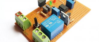
Fig.3 Breadboard assembly of the device
As you can see in the photo, the device board was assembled on a breadboard, the device in this case was powered by a battery, later the device was slightly modified to fit into the case of a computer power supply and began to be powered by a step-down transformer.
List of radioelements
| Designation | Type | Denomination | Quantity | Note | Shop | My notepad |
| PWM controller | TL494 | 1 | Search in the Otron store | To notepad | ||
| MOSFET transistor | IRFZ44N | 1 | Search in the Otron store | To notepad | ||
| Rectifier diode | KBU6M | 4 | Search in the Otron store | To notepad | ||
| Diode bridge | RC207 | 3 | Search in the Otron store | To notepad | ||
| Rectifier diode | 1N4007 | 1 | Search in the Otron store | To notepad | ||
| Rectifier diode | SBL2040CT | 2 | SB2040CT | Search in the Otron store | To notepad | |
| Electrolytic capacitor | 10 µF 50 V | 2 | Search in the Otron store | To notepad | ||
| Electrolytic capacitor | 2.2 µF 63 V | 1 | Search in the Otron store | To notepad | ||
| Electrolytic capacitor | 1000 µF 25 V | 1 | Search in the Otron store | To notepad | ||
| Capacitor | 1 pF 63 V | 1 | Search in the Otron store | To notepad | ||
| Electrolytic capacitor | 2200 µF 50 V | 1 | Search in the Otron store | To notepad | ||
| Electrolytic capacitor | 2.2 µF 50 V | 1 | Search in the Otron store | To notepad | ||
| Capacitor | 2200 pF 4 kV | 1 | Search in the Otron store | To notepad | ||
| Capacitor | 470 pF 30 kV | 1 | Search in the Otron store | To notepad | ||
| Resistor | 16 kOhm | 1 | Search in the Otron store | To notepad | ||
| Resistor | 220 kOhm | 1 | Search in the Otron store | To notepad | ||
| Resistor | 10 kOhm | 2 | Search in the Otron store | To notepad | ||
| Resistor | 47 kOhm | 1 | Search in the Otron store | To notepad | ||
| Resistor | 68 Ohm | 1 | Search in the Otron store | To notepad | ||
| Resistor | 1 kOhm | 1 | Search in the Otron store | To notepad | ||
| Variable resistor | 50 kOhm | 1 | Search in the Otron store | To notepad | ||
| Variable resistor | 10 kOhm | 1 | Search in the Otron store | To notepad | ||
| Resistor | 100 Ohm | 1 | 6 W | Search in the Otron store | To notepad | |
| Resistor | 1 MOhm | 1 | 3 W | Search in the Otron store | To notepad | |
| Multiplier | UN8.5/25-1.2 | 1 | Search in the Otron store | To notepad | ||
| Arrester | 0.5 mm | 1 | Search in the Otron store | To notepad | ||
| TR1 | Transformer | 1 | Search in the Otron store | To notepad | ||
| TR2 | Transformer | 1 | Search in the Otron store | To notepad | ||
| TR3 | Transformer | 1 | Search in the Otron store | To notepad | ||
| SV1 | Switch | 1 | Search in the Otron store | To notepad | ||
| Add all | ||||||
Attached files:
- high_u_bp(Layout 4).lay (37 KB)
Tags:
- power unit
- Sprint-Layout