As you know, repairs are akin to a small-scale natural disaster, and one of its integral components is the electrification of residential or business premises. We remember how important a role electricity plays in a home when it suddenly disappears due to an accident. Providing an apartment or private house with electricity, as a rule, includes two basic components: installation of electrical wiring and assembly of an electrical panel.
Each of these components involves the sequential implementation of a number of steps, which at first glance are quite simple, however, as practice shows, in the vast majority of cases, requiring the participation of a professional electrician. If the owner of the premises intends to independently solve the problem of supplying electricity to a house or apartment, it is necessary, at a minimum, to carefully study the hardware, that is, prepare theoretically, before assembling the electrical panel with your own hands.
The electrical panel is the heart of the home electrical system.
We will not be mistaken if we say that the main function of an electrical panel installed at home, in an office, a cafe or any other room is to distribute electricity to consumers and ensure safety when using electrical appliances. Every owner of a residential or business premises at some point is forced to deal with the problem of how to assemble an electrical panel. Long-term uninterrupted operation of the huge number of household appliances that fill any home or office today largely depends on how correctly the electrical panel is assembled.
The shield itself is a plastic or metal box in which components (or modules) are placed, each of which performs a specific function. There are so-called internal electrical panels, that is, recessed into the wall, and external ones, located on the wall.
In a private home, the electrical panel is often installed outdoors; in this case, a waterproof design of the device will be required (protection level IP65). Considering the fact that it is unlikely that the electrical panel will be changed annually or even once every five years (as a rule, the device lasts much longer), it would be advisable when choosing a device to give preference to a more expensive, but high-quality panel of a well-known brand with a supply of seats.
Purpose and types
An electrical panel is a distribution box designed to accommodate input devices, protection elements and an electricity meter. This box is used both at production facilities and in private houses and apartments. In the technical documentation you can also find another name for it - distribution point.
In fact, the device is a box with seats for mounting electrical fittings. Its design includes a door designed not only to protect the equipment located in the cabinet, but also to prevent electric shock. Depending on the purpose, shields produced by industry can be:
- Central. They serve to distribute electricity throughout the facility and are intended for planting power cables from the substation.
- Group. Used to manage nodes and individual groups.
- Household. They are located at the entrance to an apartment or private house and connect all current consumers.
- Storey. Typically contain equipment that controls power lines for multiple apartments.
- Emergency. Using automatic equipment, the main power supply is switched to backup power.
- Lighting. They contain only circuit breakers that protect the lines coming out of them from overloads.
Thus, electricity is supplied to socket or lighting groups from the switchboard. In a floor or apartment unit, all the electrical equipment necessary for this is installed, for example, package circuit breakers, RCDs, voltage relays, input differential circuit breakers, neutral and grounding voltage blocks. In addition, an electricity meter can be mounted in it.
The requirements for different types of shields are the same. They are designated in the operating rules for electrical installations (PUE) and GOST 51321. The main content of these documents is as follows:
- ignition protection for an outdoor electrical box must be of a high class;
- the design of the box must be resistant to mechanical stress;
- the device must be equipped with strips and clamps for reliable fixation of the modules;
- The design elements of the switchboard must withstand voltage surges of up to 2.5 kW for at least a minute.
Types of shields
The division of panels according to purpose is conditional and is intended to be indicated on building plans or in other documentation understandable to specialists. For consumers, electrical cabinets are divided according to other criteria. First of all, this includes installation, which can be built-in or wall-mounted.
You might be interested in How the Hall effect is used: principles of the phenomenon and methods of application
The built-in (internal) structure looks more attractive, since it forms almost one whole with the wall on which it is placed. The second type is hung using fasteners, which allows it to be used even on thin partitions. It should be noted that there is also a floor-type panel, made in the form of a cabinet and used only in production.
In addition, electric boxes vary in size and material from which they are made. Metal or plastic is used as a base for them. There is no fundamental difference between the use of one material or another, but for built-in or outdoor use a plastic box is recommended, although the metal one is vandal-proof and has a lock.
All shields have their own markings, consisting of letters and numbers. So, ShchKU means apartment metering panel, ShchKR means distribution panel, ShchRV means internal, and ShchRN means mounted. The number after the abbreviation indicates the number of modules that can fit in the device. For example, the marking ShchRN-10 means that the electrical cabinet is intended for wall-mounted design and is designed to install ten modules.
There are also models that have a mounting panel. They are designated SHMP. Due to their small dimensions and good appearance, they can be used both in floor niches and in apartments. The difference between outdoor devices (SHRNM) is the ability to remove the mounting panel, which allows you to increase the useful volume of the box.
Characteristics of distribution blocks
The technical parameters of distribution boxes for electrical machines are related to ergonomics and the number of simultaneously installed modules. Thus, the quality of the device depends on the accuracy of the fit of the elements, the type of materials used in the manufacture and the coating of the metal parts. The following design characteristics are distinguished:
- Dimensions. Indicated in millimeters. Most often, the electrical panel is made in a rectangular shape.
- Number of modules. Indicates the number of seats for electric machines. It should be noted that some devices, for example differential automatic machines, can occupy more than two places. The unit of measurement is pieces. Additionally, space may be provided for installing an electricity consumption meter.
- Material. Shields are made of metal or non-flammable plastic.
- Place of use. There are options for outdoor and indoor execution.
- Door type. If the electrical panel has a door, then it can be transparent or solid. It is made of sheet metal or plastic and can be supplemented with a fire-resistant seal, as well as have a latch or a full-fledged lock.
- Type of instalation. There can be three types: wall-mounted, built-in, floor-mounted.
- Level of protection. This value corresponds to the standard international classification. It is characterized by an IP protection system, which determines the degree of withstanding the impact of solid objects and water, and IK, indicating resistance to impacts (the more, the better).
- Color. They are available in a variety of colors and may have the texture of wood or other decorative material.
You might be interested in Electrical engineering and electronics as the basis of physics
Where to start?
Every experienced electrician will confirm that it is much easier to begin work on installing an electrical panel and wiring, having before your eyes a floor plan indicating the intended placement of household appliances, lighting fixtures, as well as sockets and junction boxes. Having decided on the number and power of consumers, it is necessary to draw up a diagram of the electrical panel itself. A single line diagram might look like this:
In this diagram, all consumers are divided into 20 groups, for each of which the following is indicated:
- wire grade and core cross-section, mm²;
- power;
- current consumption;
- type of circuit breaker indicating the rated current.
For the uninitiated, such a diagram looks quite complicated, so you can use a simplified schematic representation of the location of the electrical panel components.
For greater clarity, the electrical panel diagram can be depicted as follows:
Or even like this:
Where
- 1 - introductory AB;
- 2 - counter;
- 3 - zero bus;
- 4 - grounding bus;
- 5–10 — AV consumers.
Having such a diagram in hand, it is much easier to figure out how to properly assemble an electrical panel.
Typical installation mistakes
Most often, when installing electrical wiring, and in particular connecting a machine, the following mistakes are made:
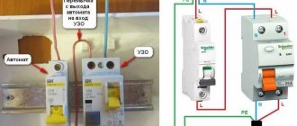
- The power wire is inserted from below. Despite the fact that this electrical installation option is not prohibited by the PUE rules, we still do not recommend connecting the circuit breaker from below, especially since even on the front panel of the case there is a diagram in which the installation location of the fixed contact is at the top (as shown in the photo below) .
- The contacts are clamped too tightly with the fixing screw. This should not be allowed, because as a result, you can not only damage the cable core, but also deform the body of the product.
- The conductors are not connected correctly. A prerequisite is that the phase must be connected under the phase, zero under zero (if a two-pole switch is used). We immediately recommend that you familiarize yourself with the material: color coding of wires.
- Instead of one two-pole circuit breaker, two single-pole circuit breakers are used. This is strictly prohibited, because... phase and zero must be disconnected at the same time.
- When fixing the core, insulation gets into the seat. Be sure to strip the wire as much as required by the model data sheet. If you press down on the insulation with a screw, the contact of the conductor will weaken, as a result of which the core will heat up and further adverse consequences will occur. For this task, we recommend using a special tool for removing insulation.
- The choice of circuit breaker is incorrect; in particular, the product is not able to withstand the incoming loads. In this case, first you need to correctly calculate the cable cross-section and, according to the calculated characteristics, select the appropriate model.
- When calculating a suitable circuit breaker, the value is rounded up. For example, you calculated that the current load on the product is 19 Amperes. According to the simplest logic, novice electricians go to the store and purchase a device of the closest value for connection - 20 Amperes. This is a huge mistake, because... the calculated value is nominal, and it turns out that the protection will operate when the wiring is slightly overloaded. It is better to purchase a switch with a rating of 16 Amps, so the electrical wiring will last longer.
Another important point on which there is a lot of discussion is whether it is possible to connect the machine in front of the electricity meter or is this done only after it? The answer is that it is possible, and even necessary, the main thing is to buy a special box, which is sealed by energy sales representatives. Installing an input machine in front of the electric meter will allow you to safely replace the electricity control device both in a private house and in an apartment.
Here, in fact, are the rules for installing and connecting an electrical machine with your own hands. Now let's move on to the main topic of the article.
How to properly form consumer groups
When distributing electricity consumers into groups, you should adhere to certain rules:
- powerful consumers (2 kW or more), which usually include a hob, oven, water heater, washing machine, etc., should be powered by a separate switch. The cable must go from the panel to the consumer, bypassing the distribution boxes;
- two-kilowatt consumers are connected with a copper cable with a cross-section of 2.5 mm² and a 16 A circuit breaker. If you are guided by the tabular data, then for a 2 kW device a 1.5 mm² wire, as well as a 10 A circuit breaker, is sufficient, but to create some reserve, as a rule, the components of the following are installed level;
- in some cases (if the consumer power exceeds 2 kW), a 4 mm² wire with AB 25A or a 6 mm² wire with AB 32 A may be required - such components are sometimes used when connecting a hob, oven or instantaneous water heater;
- for each room you should make a separate socket line, which will branch out from the distribution box into the required number of sockets;
- the same applies to the lighting line - each of them is connected, as a rule, by a 10 A automatic machine and a 1.5 mm² wire.
It is this approach to the distribution of consumer groups that can ensure uninterrupted and safe operation of home and office electrical appliances. It is extremely undesirable to use components and materials of dubious origin, even if they are an order of magnitude cheaper than “branded” ones: with a high degree of probability, such parts will have to be replaced in the near future.
The socket line is usually equipped with a 16 A circuit breaker.
Connection diagram for machines in the panel
The layout of the panel in the apartment is one of the main points, but before we deal with it, let's see what elements are included in the design. So that you can understand the symbols and composition of the wiring diagram.
Typically, when installing a shield, use:
- Introductory machine. It is placed to protect the entire wiring circuit. The cores of the main incoming cable are connected to the terminals of the input circuit breaker. For convenient work with the electrical panel, a switch is often installed in front of the input circuit breaker. It allows you to de-energize the entire assembly to replace elements, safe preventative maintenance, and completely shuts off the power supply to your apartment or house. In this case, the power cable is connected to the switch.
- Electricity meters. It is installed after the introductory machine and calculates the energy consumption in a house or apartment. Sometimes the meter stands separately, up to the panel, along with a circuit breaker. For example, on the site of an apartment building.
- Residual current device (RCD) . The RCD in the circuit can be one, installed after the meter, for example, in a one-room apartment with a small load. Or they install several RCDs on separate lines with high consumption (for an electric stove, washing machine, air conditioner).
- Linear machines . Needed for separate lines for different rooms, household appliances and lighting. They break the circuit if an overcurrent or short circuit is detected, protecting the wiring and connected equipment from damage. Triggering the machine can prevent a fire due to heating and ignition of the wire.
- Automatic protection device . It can be installed instead of a pair of automatic circuit breaker + RCD on separate power lines of electrical appliances.
- DIN rail . Attached to the rear wall of the electrical panel housing. Depending on the dimensions of the cabinet, the number of DIN rails and the possible number of installed modules may vary. In order not to make a mistake when purchasing a switchboard housing based on the number of modules, you need to draw up a wiring diagram.
- Connecting busbars . Needed for disconnecting the electrical panel and connecting working zeros and grounding wires. The panel uses both neutral terminal bars and grounding ones.
- Distribution buses . Installed for a “bundle” of linear machines, RCDs, and automatic circuit breakers. Comb busbars have reliable insulation and allow you to quickly and safely connect a number of machines through the input terminal block. They can be used both for the current conductor and for the working zero.
Electrical Panel Components
The assembly of an electrical panel requires the presence of mandatory components, which include circuit breakers, residual current devices (RCDs), electricity meters, buses, as well as additional and auxiliary components that add convenience to the operation of the panel: voltage control relays, light indicators, digital voltmeters, contactors and etc.
Among the most respected by specialists are the manufacturers of components used in the installation of electrical panels - ABB, Legrand, Shcneider Electric. The prices for devices of these brands are approximately the same. Chinese devices are much cheaper, but practicing electricians claim that once you use Chinese equipment to complete an order, you can lose your reputation for a long time, so they use such components only at the request of a customer who cannot afford branded components.
RCDs and circuit breakers on a three-phase switchboard
Let us examine in detail a not entirely standard circuit assembled on a three-phase distribution panel.
It contains:
- three-phase input circuit breakers - 3 pcs.;
- three-phase residual current device - 1 pc.;
- single-phase RCDs - 2 pcs.;
- single-pole single-phase circuit breakers - 4 pcs.
From the first input circuit breaker, voltage is supplied to the second three-phase circuit breaker through the upper terminals. From here, one phase goes to the first single-phase RCD, and the second to the next.
The voltage from the second input circuit breaker is supplied to a three-phase RCD, the lower terminals of which are connected to a three-phase load. This protective device protects against leakage currents, and the second input circuit breaker protects against short circuits.
Single-phase RCDs installed on the panel are two-pole, and automatic machines are single-pole. For the protective device to function correctly, it is necessary that the working zeros after it are not connected anywhere else. Therefore, after each RCD, a zero bus is installed here.
When the machines are not one-pole, but two-pole, then there is no need to install a separate zero bus. If two zero buses are combined, false positives will occur.
Each of the single-pole RCDs is designed for two circuit breakers (1-3, 2-4). A load is connected to the lower terminals of the machines.
The common ground bus is installed separately. Three phases enter the input circuit breaker: L1, L2, L3 and the working neutral wire.
The zero is connected to the common zero, and from it goes to all the RCDs. Then it goes to the load: from the first device - to three-phase, and from the next single-phase - each to its own bus.
In a three-phase network, electrical quantities are vector, therefore their total value is determined not by the algebraic, but by the vector sum of these quantities
Although this distribution panel has a three-phase input, the wire is not divided into PEN and PE, because five-wire input. Three phases, zero and grounding come to the shield.
Everything is ready for installation
So, the diagram has been drawn up and understood, the components have been prepared - nothing prevents you from starting assembling the electrical panel. First of all, the location of the shield is selected, on which the device is attached, as a rule, with self-tapping screws or clamps. The electrical panel housing is usually located near the entrance to the house or apartment - in the vestibule or hallway. If the owner has expressed a desire to hide the panel in the wall, and the wall turns out to be concrete, you can use a false wall or a plasterboard ledge: the area of the room may be slightly reduced.
When choosing a place on the wall to install an electrical panel, you should take into account that the distance from the device to the nearest doorway should be at least 15 cm, the distance to the floor - 1.5–1.7 m. If necessary, the owner of the home or a called electrician should be able to easily reach the panel : It is strictly prohibited to place the device inside cabinets or other furniture. The device should be located away from gas pipes and flammable materials.
To prevent the electrical panel from being too large or small, you can first determine its size by knowing the dimensions of the components that will be located in it. For example, the width of a standard single-pole circuit breaker is 17.5 mm, a two-pole circuit breaker is 35 mm, and a three-pole circuit breaker is 52.5 mm. The remaining components have the following dimensions:
- RCD single-phase two-module - 35 mm;
- Three-phase four-module RCD - 70 mm;
- single-phase two-module difavtomat - 70 mm;
- terminal block on DIN rail - 17.5 mm (1 module);
- counter (6–8 modules) – 105–140 mm;
- voltage relay of 3 modules - 52.5 mm; This is not a mandatory element of the shield, but when used, you can protect equipment from power surges or sags, and save household appliances such as a refrigerator, TV, computer and other electronics from failure;
- DIN rail socket (3 modules) - 52.5 mm.
The modules are located on the so-called DIN rail - a special metal plate 35 mm wide. The socket is not one of the required elements, but may be useful during repair work. If, when summing up the number of components, it turns out that a panel with 20 modules is needed, then it would be reasonable to install an electrical panel with 24 or even 32 modules - who can know how many household electrical appliances will be added to the house in a year, two or five?
Installation and assembly of electrical panel
The electrical panel includes complex modular equipment. If necessary, you can carry out the installation yourself, but first you need to learn how to properly assemble the shield.
To separate the work of electrical components and housing installation, you should purchase a panel that has a removable frame and DIN rails.
There are several types of electrical panel installation:
- wall mounting;
- installation in the wall.
Let's consider the second option, since the first one is installed simply on holders. Before you hollow out an opening in the wall, you need to make sure that it is not “load-bearing” in the house. According to the rules, installation work cannot be done in it.
It is recommended to install electrical panels near the front door. This is a corridor or hallway with good lighting and normal air humidity.
The electrical panel must be visible. Doors should not impede his access. For safety reasons, the shield should not be placed near gas pipes or other flammable substances. To place it on the wall, it is necessary to take into account the height from the floor to its lower edge of at least 1.4 m, and the distance of the upper edge from the floor is no more than 1.8 m.
A building level will help mark out the future area. To maintain all dimensions, you can attach the body to the wall and outline it with chalk. A slot is made using a grinder along the marked lines.
A chisel and a hammer drill will help to hollow out the inside. You need to check the depth of the resulting niche by inserting the electrical panel housing into it.
First, the mount included in the kit is mounted there. Then the electrical panel. For fastenings, holes are made and dowels are inserted. The remaining cavities are sealed with polyurethane foam.
DIN rails are unscrewed from the electrical panel in order to install modular equipment on them. If the kit does not include special fasteners, then you need to drill holes in the back wall of the shield for future fastenings. This is done carefully; excessive force may cause the housing to burst.
We run cables into the electrical panel
Having a special cable entry with a removable cover can eliminate problems with wiring cables into the panel. On high-quality panels, such an input is usually provided; low-quality ones are better not to be considered at all. If the electrical panel is installed outside, there are usually no problems with cabling. If the shield is hidden in a niche, there may be nuances: getting to the inlet hole in this case can be quite difficult, so the electrician needs to be patient and persevering.
The design of the cable entry of the electrical panel, as a rule, provides for perforated holes, which are brought to the required size by simply removing excess jumpers. The cables are fed into the shield through a corrugated pipe, the standard size of which is 16 or 20 mm; accordingly, the holes should be made of this size.
Often the electrician is hampered by the mobility of the wires inside the corrugated tube. To fix the wires and make them stationary, some use alabaster, which is applied to the input hole from the side of the gate. Let us immediately make a reservation that this method of fixation is not convenient and aesthetically pleasing. It is much more efficient to secure the wires using special removable plugs or gland plates.
To avoid future confusion with wires, you should immediately label them. The input cable is usually connected in the upper left corner - where the input machine is usually installed.
Installation of distribution boards
After all the preparatory work has been completed, you can proceed directly to installation. It is better to perform it on an uninstalled switchboard and then connect it to the electrical wiring.
Single-phase distribution boards
The most common are lighting panels with single-phase consumers. These are floor, apartment or distribution boards for a private house. Therefore, we will begin the story with them.
The photo shows a single-line diagram of the lighting panel
So:
- Before you begin installation, it is highly advisable that you have at least a single-line diagram of the lighting board. By the way, you can then attach it to the switchboard door, which is what the rules require.
- The installation process itself begins with attaching the so-called DIN rails. All modern protective and switching devices can be easily attached to them. Some lighting panels already have these slats, but they may need to be modified to suit your requirements.
- In addition to DIN rails, it is advisable to immediately install busbars for fastening wires. These tires can be attached either to slats or directly to the box. It depends on the tire design.
- At the next stage, we attach our equipment to the slats. This is done quite simply due to the spring mechanism, which is equipped with almost all modern devices. If the device does not have a DIN rail mount, you can purchase a special mount.
- Now let's talk about the location of equipment in the switchboard. Even when designing a lighting board, it is assumed that an introductory machine will be installed. It is located at the top. If you plan to install a large amount of additional equipment, then it is usually allocated to the upper left part of the panel.
Note! According to the PUE standards, the main power supply is always on the left. If there is backup power, it is located on the right. Therefore, if you open an electrical installation and don’t know where and what is located, then you can know with confidence that you have an input machine installed in the upper left corner. If there is an automatic backup power supply, then it is installed on the right.
- If your switchboard does not have an input circuit breaker, then in its place we install terminal blocks or busbars. From which we will then power the group machines.
- If there is an input circuit breaker, then the terminal block for the phase wire is installed immediately below it. Terminal blocks for the neutral wire and protective grounding can be located below. In some cases, they are installed on the side surface of the cabinet.
- We will power the group circuit breakers from the phase terminal block. Therefore, they are located below the tires.
Three-line switchboard diagram
- If you plan to install RCD machines, then they are located below the group machines. In the same row there is additional equipment for this group, for example, impulse relays, protection against voltage changes for this group, and the like.
Note! If you plan to install RCDs, then it is better to place a bus or terminal block with neutral conductors below the group RCDs, but above the RCDs. In this case, the protective grounding bus is located below the RCD circuit breakers. If there is space, then additional equipment is located even lower. If there is no space, then the purpose of the pulse relay in the lighting panel and other additional devices should be on the side of the panel.
- The design of the group lighting panel should include the installation of other additional equipment. It is usually located in the upper right side. Moreover, it is better to install overvoltage protection and power quality monitoring devices before the input circuit breaker.
- Once all the power equipment is installed, you can begin connecting it. This is where a complete schematic diagram of the lighting board will come in handy, which will allow you to trace every wiring.
Note! When distributing equipment, remember that placing any equipment or terminal blocks on cabinet doors is prohibited.
- After the distribution panel is disconnected inside, it can be mounted at a permanent installation location and the power and consumers can be connected there.
Three-phase lighting panel
The installation and production of three-phase lighting panels is practically the same, but there are also certain nuances here. We will dwell on them in more detail.
Wiring diagram of a three-phase lighting panel
So:
- The main difference between a three-phase switchboard is the ability to connect both three-phase loads and single-phase loads from it. Moreover, depending on the type of load, it is possible that a single-phase load is powered from two or three different phases.
- The first possible option is power supply from an input circuit breaker for three-phase and single-phase loads. In this case, it is advisable to place three busbars of phase wires below the input circuit breaker. Three-phase and single-phase loads are powered from them. Otherwise, the principle of constructing the switchboard is similar to that discussed above.
- If only single-phase loads are supplied from a three-phase input circuit breaker. Then in this case, below the input circuit breaker, at the same level, we install three busbars for phase conductors. From each of these buses we power separate groups.
Note! If you connect lighting groups from a three-phase network, they must be separated. It is desirable that different phases power different buildings, lighting billboards of different types, different types of loads that would be difficult to connect during operation.
Distribution boards ready for installation
Distribution boards, ready for installation, as shown in the video presented, are quite widely available on the market. They already have all the necessary equipment, which is disconnected and ready to connect.
There are many types of such shields and it is useless to describe each of them. Therefore, we will present only the designation standards for such distribution boards, which must comply with GOST 32397 - 2013.
Option for connecting a ready-made distribution board
- The designation for the configuration and type of execution is applied in the upper part of the shield. The first character indicates the presence of an introductory machine. If the number is 1, then this means that a switch without built-in protection is installed here. The symbol “1A” indicates the presence of a switch with built-in protection. The symbol “1D” indicates a machine with built-in residual current protection. “0” indicates the absence of an introductory machine.
- The next two or three digits indicate the rated current for which the distribution panel is designed.
- Next, the number of circuit breakers and RCDs is indicated through a fraction.
- In addition, in the designation you can find symbols such as “U”, which indicates the need to build this shield into a niche. The “Sch” symbol indicates the presence of a meter in the panel. The symbol “F” indicates additional control and alarm devices, which is why the price of the shield becomes higher.
We cut the cables and mount the modules
Every electrician will confirm that working with a tool specifically designed for a particular operation is easier and more enjoyable. You can cut the cables inside the shield with a regular construction knife, but if you do it with a special knife with a heel, everything turns out faster and better.
After cutting the cables, you should re-label the wires, since there will be quite a lot of them and if you get tangled in them, it will take a lot of time to restore order. When feeding cables into the shield, you should leave a length that is equal to twice the height of the shield, that is, run the cable through the entire shield, and then measure out the same amount. This measure is not wasteful: the wires inside the shield do not go in a straight line, but along an intricate curved line, and it is better to have a little extra wire left than not enough.
There are no strict rules for the arrangement of modules in the electrical panel; however, electricians usually use one of two installation schemes - linear or group. In the first case, all elements are arranged one after another in the order shown on the single-line diagram: automatic input device, RCD, automatic circuit breakers, consumer circuit breakers. Among the advantages of this location option is ease of implementation, the disadvantage is that it is difficult to find the “culprit” of the emergency situation.
If a group layout of modules is implemented in the panel, the components alternate among consumer groups: AV input, RCD, group of switches linked to this RCD. Next, the next RCD and the corresponding group of circuit breakers are installed. Such a circuit is somewhat more difficult to assemble, but the problem line is immediately visible from the triggered RCD.
Electrical panel for meters and machines: choosing an installation location
Let's start with the simplest part - where to place the switchboard in the apartment? It is most convenient to place it near the front door in the hallway. In this case, you will not have to pull the power cable far from the site. The best height option is at the eye level of an adult. And it’s convenient to take meter readings and turn off the machines if necessary.
For those who support pushing everything under the ceiling, “for greater security, like they used to hang meters,” let’s say the following. Old electric meters with fuse plugs were simply mounted on the wall without boxes, and therefore were hung from the ceiling.
A modern electrical panel has a durable casing and is locked, so children will not get in unless you leave the key in a visible place.
When choosing a location for installing a panel in a private house or cottage, you need to consider where and how the cable from the overhead line or underground supply line is or will be installed. Data on external networks can be obtained from local energy sales.
Buy a ready-made one or assemble an electrical panel yourself
As they say in the old song “what progress has come”, you can buy a ready-made shield with a full filling or assemble a ready-made one. If your electrician suggests such a “proprietary” assembly design, then do not be alarmed. The panels are assembled by enterprises and electrical installation companies, including on order or for standard residential wiring projects.
The main point that needs to be clarified is whether your master has worked with ready-made shields before or this is his first experience. If he has installed a dozen or two such assemblies and knows their features, then feel free to agree. But if you are a “guinea pig” for the first experiment, refuse. It’s better to let him assemble it himself, with his own hands, the old fashioned way.
Assembly Rules
There are certain rules that should be followed when assembling an electrical panel:
- all wires inside the panel must be of the same cross-section as the input wire;
- any module must have an entrance at the top, an exit at the bottom;
- if installation is carried out using PV3 stranded wire, it is necessary to use NShVI lugs.
The sequence of steps for an electrician performing the assembly may look like this:
- preliminary arrangement of modules on DIN rails in accordance with the existing diagram;
- fixing modules on DIN rails using special fasteners;
- installation of comb buses, with the help of which voltage from the AV input is supplied to the remaining modules;
- distributing the phase to its destination from the lower terminals of the modules using wires with lugs;
- installation of the neutral wire. All wires are mounted behind the DIN rail;
- tightening all connections using a screwdriver;
- supplying voltage to the input machine and checking the functionality of the modules;
- checking the presence of voltage at the inputs and outputs of the modules using a multimeter.
Step-by-step instructions on how to connect a single-core wire
After you have purchased the RCD and all the necessary devices for installation, you can begin to work. It must be remembered that all stages of installation must be carried out sequentially and all safety measures must be taken.
Practical advice
Experienced electricians recommend installation in the following sequence:
- de-energize the shield. Check the presence of current using the indicator;
- care must be taken to ensure that no one unexpectedly turns on the electricity;
- the equipment must be firmly snapped onto the DIN rail;
- Electricians recommend connecting the device according to this principle - all incoming wires are at the top, and outgoing wires are at the bottom. This generally accepted scheme will help avoid confusion when replacing equipment;
- there should be no kinks in the wiring when connecting;
- disconnect excess parts of the cable with wire cutters;
- Carefully remove the insulation from the cable by 10 mm;
- Install the cable into the required terminals and secure it. It is necessary to monitor the clamping force - tightly twisted terminals will quickly lead to breakage of the switch;
- turn on the power supply;
- check the voltage access to the switch using an indicator.
Common Mistakes
Sometimes it happens that the power switch does not perform its functions, so you have to reinstall it again. To avoid malfunctions, you need to avoid the following installation errors:
- the insulation from the wire has come into contact. If the insulation is not removed before installation, this increases the risk of a short circuit that leads to a fire;
- connecting several wires with different cross-sections to one terminal. In this case, only a large cross-section core is tightened well, and thin wires have poor contact, which leads to melting of the housing and a fire. This happens when connecting various devices to the switch. To avoid this, you need to use jumpers between cables and devices. They are made from wires of the same cross-section;
- Do not connect copper and aluminum wires together. The device will become unusable due to the oxidation process when two metals are combined;
- You should not connect a straight wire to the terminal, but you need to bend it with a hook, which will increase the contact area and increase the performance of the device; such a cable is also more difficult to pull out of the device.
The final stage
The shield is installed in its place after all dirty repair work is completed. The panel body is mounted in a niche, the DIN rails with the assembled modular equipment are fastened with self-tapping screws. The working (N) and protective (PE) zero buses are fixed. Phase and neutral wires are arranged in separate bundles and laid on opposite sides of the shield. The force with which the connections are clamped is 0.8 Nm.
Before starting commissioning work, you should make sure that all sockets, junction boxes, and switches are assembled. All consumer groups should be signed on the external panel of the electrical panel. After about a month of work, all connections of the shield should be tightened.
CS-CS.Net: Laboratory of the Electroshaman
Boiler room automation panel, in which all the wires are tightly tied together
ATTENTION! In this post, I do not scold Meldir in any way, but describe our personal experience with him, which will be useful to others and thanks to which I have forever decided not to dig the wires into the shields deep and far, but to lay them as freely as possible.
I will raise one small issue, in the solution of which I am still ingrained and do not want to change it - I just want to improve it. This question is about fixing the mounting wires when assembling the panel . The fact is that in shield assembly schools there are two warring camps. One of these camps can be called “Designers”, and the second “Practitioners”.
Designers strive to get a beautiful installation of the shield and therefore try to bundle all the wires and firmly fix them with ties. Additionally, they hide the wires behind the DIN rails in such a way that the shield is half empty: there is nothing superfluous, everything is clean and tidy.
Practitioners are former designers after they worked in the fields with their own shield and reached the point of “What kind of asshole secured everything like that! Fuck, you'll come up, you motherfucker! Ah.. so it’s me! I wish I could do this again!” Practitioners understand that beauty does not belong everywhere and beauty should not interfere with work. In front of you is a boiler room panel with automatic phase switching and well pump control. Meldir assembled it for one of the orders. He wrote about him on the community. Pay attention to the photos from there - everything there is assembled just like a designer. It seems to me that any shield builder starts with a design approach and then has to grow from there.
What is the reason that we tightly tighten and hide the installation wires in the panels? And the fact is that the panel assembler does not think tens of years ahead: that something will have to be changed, altered or repaired. What if the automation we made is no longer needed and needs to be replaced? And in all these cases, it will be necessary to pull the beautifully laid wires and shake them up.
In general, training using the Hanged Man method (a lasso in the Tarot that rattles very strongly) in the fields is the best way to understand why it is impossible to hide and firmly fasten wiring wires in a shield. This very boiler room shield gave me and Meldir some fun...
It all started with the fact that Meander RVF-01 was used as a phase switch. And then it went so fucking wrong that I even scolded it in the community and constantly promised, as soon as I dealt with the problem, to write about what crap Meander is doing. RVF-01 was replaced by RVF-02, which also began to fail...
..and then Meldir called me, and I made a verdict: “Meander - into the furnace! We install NovaTek PEF-301,” which I had lying around at home in reserve. RVF-01/02 occupy one module, and PEF-301 - three modules. And that’s when it was necessary to move the contactors and shake up their connection diagram a little.
I started to sort through the shield. I happily twisted the RVF, a couple of contactors and, thinking that I was now “I’ll tighten this wiring,” I came across the ties =) I was very naive, thinking that I could tighten the harness and see through part of the ties - Meldir was so driven to assemble this shield that he secured the ties to the adhesive pads behind the slats. And to prevent the pads from coming off, I also glued them with super glue.
Part of the automation has been dismantled in the switchboard - but the wires cannot be reached!
Therefore, the swearing began when it was necessary to climb behind the rail. Some of my students actually love to screw a perforated box behind the DIN rails and hide all the wires there. It will look fucking beautiful too. But what happens if you need to change something? After all, the shield will be installed and connected and there will be no access to the rear of the frame AT ALL!
All wires are tightly tied together and glued behind the rail
As a result, we had to further disassemble the shield and remove the entire DIN rail from it. After that, we were able to cut through the ties and free the necessary wires in the harness.
All wires are tightly tied together and glued behind the rail
As a result, after reworking the shield, we ended up with this installation. The cross-module for collecting power from the contactors had to be thrown on the side because there was no free space left in the shield. By the way, this is also a lesson for everyone - leave as much free space in your shields as possible. There was free space in this panel, but it turned out that it was necessary to add a dozen automatic machines for the boiler room pumps, and this space was gobbled up. All this must also be taken into account when assembling shields!
Converted boiler room panel
CONCLUSIONS. For myself, I decided one thing: I’m not going to chase designers and leave my old methods of assembling panels and routing wires, namely:
- I lay the mounting wires behind the DIN rails, hoping that people will connect the wires of the outgoing lines on top of the module (not behind the DIN rails). Therefore, I write in my instructions that in my switchboards, in no case should the wires of outgoing cables be routed behind DIN rails.
- I lay the installation wires along the shortest routes. If these routes are short and go along adjacent DIN rails, then I do not tighten or fix them.
- I record only those wire routes in the switchboard that can be called “main”: from the contactor to the cross-module. From some remote terminals (at the bottom of the shield) to the module in the middle of the shield. In these cases, it makes sense to bundle the wires from these terminals and secure this particular bundle.
- Where there will be a lot of wires and they will go along a common route (for example, from the PLC to the relay block), I will try to install some open holders or a perforated box so as not to bundle the wires together. But these holders or the punch box must be open on TOP of the panel, and not behind the DIN rails!
- In power cabinets (TwinLine, for example, which I am currently assembling) I will use cable holders from the EDF/WR system (ED44P10, ED45P10 -
). These holders are not designed to provide a closed wire route, but to support the wires! Here's their value and why I'll use them. Such holders will prevent the wires from spreading out, but at the same time they will allow you to remove or pull out a separate wire from the bundle!
Here's a snippet of the interior installation of my first large TwnLine cabinet. At the very top corner of the photo you can see the harnesses tied together with ties - this is the power that comes from the reversing switches to the contactors and from the contactors to the cross-modules. These lines are three-phase (3L+N), so they can be bundled together and not be touched. Or touch it entirely.
But after the cross-modules, all the wires hang freely, because it is necessary to leave the opportunity to easily find the wire from the desired circuit breaker and switch it to another phase or even to another cross-module. My only mistake here is that I was embarrassed to order ED44P10 and adapt these wires after the cross-modules. I have already corrected myself: I began to fit several packs of these fasteners on all new cabinets.
My assembly of shields (Cs-Cs.Net). Wires lie freely in the right places
Do you see how complicated it is? Do you see how many nuances there are even in such little things? And the further I dive into ABB, the more I understand that most of their solutions were developed not just for the sake of marketing. For example, at the very beginning, these ED44P10 cable holders seemed to me to be stupid and unnecessary plastics that were expensive and incapable of properly clamping the wires. And now I understand why they were created and why they were created that way.