2019-01-03 Published 01/3/2019 authorAndrey Andreev
—
Locations, markings, USB 3.0 and other subtleties—>
before—>p, blockquote1,0,0,0,0—>
Frequent use of ports located on the rear side is not always convenient, as access to them can be difficult. Currently, most cases are equipped with USB ports on the front panel, the number of which may vary depending on the model.
p, blockquote2,0,0,0,0—>
In today's publication, I will tell you how to connect USB connectors on the motherboard correctly and what should be taken into account. At the end of the post you will find a short video with instructions on this topic.
p, blockquote3,0,0,0,0—>
Port location and markings
h21,0,0,0,0—>
Modern motherboards are most often equipped with four, six or eight such ports. Typically, two or four of them are tightly soldered in such a way that they can be accessed from the rear panel - where the keyboard and mouse jacks, audio outputs and everything else are located.
p, blockquote4,0,1,0,0—>
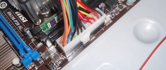
Other ports are located on the “mother” itself and are connectors with protruding pins. To connect the front ports to the motherboard, special connectors are used. With their help (and also to the USB port on the motherboard), a card reader is connected, if there is one of course.
This connector is missing one socket in the lower left corner. That is, where there should be 10 holes, there are only 9 of them. Thanks to this, it is easy to understand exactly how to connect this connector to the plug on the motherboard.
p, blockquote5,0,0,0,0—>
To connect an external port, you need to carefully push the plug onto the connector until it stops. Try not to make sudden movements left or right, as you may break one or more pins, which will cause that port to become inoperable and you will have to use the next one.
p, blockquote6,0,0,0,0—>
On the motherboard, these ports are most often located near the SATA interfaces and are marked with the abbreviation USB with a serial number. There is absolutely no difference in what exactly and where to connect - the ports work in parallel.
p, blockquote7,0,0,0,0—>
USB 3.0 and other subtleties
h22,0,0,0,0—>
However, this is true in cases where ports of the same generation are used.
p, blockquote8,1,0,0,0—>
If the motherboard has a second or third revision, and a similar situation is observed with the front panel, compliance is necessary: USB 3.0 should be connected only to the corresponding slot on the motherboard, otherwise it will operate at USB 2.0 speed.
There is no need to worry about the pinout: it is the same for both revisions. In addition, motherboard manufacturers - ASUS, MSI, Gigabyte, Asrock and smaller companies, follow the same pinout that case manufacturers follow.
p, blockquote9,0,0,0,0—>
However, keep in mind that in rare cases it may still differ from the generally accepted one. You can find out the necessary information in the documentation for the motherboard.
p, blockquote10,0,0,0,0—>
Do not worry that you can connect the USB port incorrectly - in this case it simply will not work. Fortunately, it is impossible to break your computer this way.
p, blockquote11,0,0,0,0—> p, blockquote12,0,0,1,0—>
I also recommend reading on this topic how to properly connect a hard drive, as well as two hard drives on one computer. You can find out about connecting the front audio connectors to the motherboard here.
p, blockquote13,0,0,0,0—>
And if you suddenly forgot to buy something for your iron friend, then you can find a huge selection of components and peripherals in this popular online store.
p, blockquote14,0,0,0,0—>
Thank you for your attention, friends, and do not forget to share my posts on social networks. Till tomorrow!
p, blockquote15,0,0,0,0—> p, blockquote16,0,0,0,1—>
Sincerely, blog author Andrey Andreev
after—>
What happened next
Progress does not stand still and over time a narrow circle of devices appeared for which “High-speed” was no longer enough. Then the third generation of the standard was created, and this time it had more significant changes relative to the previous one.
USB 2.0 differs from 3.0 primarily in speed, this time its theoretical maximum reached 5 Gbit/s. The current strength was also increased, from 500 mA it was raised to 900 mA.
Cables for the new version of the standard are backward compatible with the previous ones, but older cables cannot work in the new, high-speed mode. The fact is that the third generation requires cables with twice as many wires. This does not have the best effect on their price and flexibility.
USB 3.0 connection options on PC motherboard
You can identify USB 3.0 in a connector on a PC motherboard visually - as a rule, it is made using blue plastic.
Now we can definitely say that this version of the universal serial bus did not win the love of both consumers and manufacturers. Ordinary people did not like thick and expensive cables, and manufacturers did not see the point in switching to a new version of the standard when all needs were fully satisfied by the previous one.
Review of USB 3.0 flash drives
Of course, devices with USB 3.0 were not uncommon in stores, and you probably even have at least one computer flash drive of this standard, however, as a rule, the speed of such flash drives is not much different from those that only claim to support USB 2.0.
USB pinout on motherboard
The biggest problem is that there is no standardization among motherboard manufacturers for the functions of each pin, meaning pin 1 of a motherboard connector may have a different meaning from pin 1 of a motherboard connector from a different manufacturer. Because of this, each wire of the USB ports on the front panel of the case uses separate connectors. See also Pinout of USB connectors.
Pinout of the USB 2.0 connector on the motherboard. On each wire connector you can read its value, which can be +5V (or VCC or Power), D+, D- and GND.
| No. pin | Wire color | Name | Description |
| 1 | Red | 5V,VCC,Power | Nutrition |
| 2 | Red | 5V,VCC,Power | Nutrition |
| 3 | White | D- | Data- |
| 4 | White | D- | Data- |
| 5 | Green | D+ | Data+ |
| 6 | Green | D+ | Data+ |
| 7 | Black | GND | Earth |
| 8 | Black | GND | Earth |
| 9 | — | Key(No pin) | Key |
| 10 | Grey | GND | Earth |
All you need to do is install each of the wires (+5V, D+, D- and GND) in the correct locations as shown above.
Pinout of the USB 3.0 connector on the motherboard.
| No. pin | Name | Description | No. pin | Name | Description |
| 1 | IntA_P2_D+ | Data+ | 2 | ID | Identifier |
| 3 | IntA_P2_D- | Data- | 4 | IntA_P1_D+ | Data+ |
| 5 | GND | Earth | 6 | IntA_P1_D- | Data- |
| 7 | IntA_P2_SSTX+ | Data+ | 8 | GND | Earth |
| 9 | IntA_P2_SSTX- | Data- | 10 | IntA_P1_SSTX+ | Data+ |
| 11 | GND | Earth | 12 | IntA_P1_SSTX- | Data- |
| 13 | IntA_P2_SSRX+ | Data+ | 14 | GND | Earth |
| 15 | IntA_P2_SSRX- | Data- | 16 | IntA_P1_SSRX+ | Data+ |
| 17 | Vbus | Nutrition | 18 | IntA_P1_SSRX- | Data- |
| 19 | Key(No pin) | Key | 20 | Vbus | Nutrition |
Technical features of the USB standard
Among the many requirements when developing a universal standard for connecting peripherals was also security. It was necessary to make it almost impossible for the device to be damaged by applying too much current or voltage to it.
USB 2.0 connector shape: type A (classic), mini and micro
As a result, it was decided to limit the power provided via USB Gen 2 to 2.5 W. This is enough for almost all low-power devices, while more demanding devices provide their own power by connecting to the mains.
USB 2.0 connector shape: type B (simple), mini and micro
If you look closely, you will see four contacts in the wiring socket; they correspond to the four wires in the cable: red (VBUS), white (D-), green (D+), black (GND).
Pinout of USB 2.0 connectors: type A, mini and micro USB
VBUS is responsible for power and supplies 5 Volts with a maximum current of 500 mA.
Data transmission is provided by D- and D+. GND, as you probably already guessed, is needed for grounding. USB 2.0 pinout by color makes it easy to determine the purpose of each cable, which makes repairs easier.
USB 2.0 connector pinout type B, mini and micro A
However, it is worth pointing out that the number of wires in the cable may be different. The information described above concerns the most common type, called USB Type A, this is the mouse and keyboard cord; other peripherals may be connected differently.
Restricting access to USB ports
Let's look at 7 ways you can block USB ports:
- Disabling USB through BIOS settings
- Changing registry settings for USB devices
- Disabling USB ports in Device Manager
- Uninstalling USB controller drivers
- Using Microsoft Fix It 50061
- Using additional programs
- Physically disconnecting USB ports
Disabling USB ports through BIOS settings
- Enter BIOS settings.
- Disable all items related to the USB controller (for example, USB Controller or Legacy USB Support).
- After you have made these changes, you need to save the settings and exit the BIOS. This is usually done using the F10 .
- Restart your computer and make sure the USB ports are disabled.
Enable and Disable USB Drives Using Registry Editor
If disabling via BIOS does not suit you, you can block access directly in the Windows OS itself using the registry.
The instructions below allow you to block access to various USB drives (for example flash drives), but other devices such as keyboards, mice, printers, scanners will still work.
- Open the Start menu -> Run, enter the command “ regedit ” and click OK to open the registry editor.
- Continue to next section
HKEY_LOCAL_MACHINE SYSTEM CurrentControlSet Services USBSTOR
- On the right side of the window, find the “ Start ” item and double-click on it to edit. Enter the value " 4 " to block access to USB storage devices. Accordingly, if you enter the value “ 3 ” again, access will be opened again.
Click OK, close Registry Editor, and restart your computer.
! The above method only works when the USB controller driver is installed. If a driver has not been installed for security reasons, the Start setting may be automatically reset to 3 when the user connects the USB drive and Windows installs the driver.
Disabling USB ports in Device Manager
- Right-click on the “ Computer ” icon and select “Properties” from the context menu. A window will open on the left side of which you need to click on the “ Device Manager ” link.
- In the Device Manager tree, find the “ USB Controllers ” item and open it.
- Disable controllers by right-clicking and selecting the "Disable" menu item.
This method doesn't always work. In the example shown in the figure above, disabling the controllers (the first 2 points) did not lead to the desired result. Disabling the 3rd option (USB Mass Storage Device) worked, but this only allows you to disable a single instance of the USB storage device.
Removing USB controller drivers
Alternatively, to disable the ports, you can simply uninstall the USB controller driver. But the disadvantage of this method is that when the user connects a USB drive, Windows will check for drivers and, if they are missing, will offer to install the driver. This in turn will allow access to the USB device.
Prevent users from connecting USB storage devices using a Microsoft app
Another way to block access to USB drives is to use Microsoft Fix It 50061 (https://support.microsoft.com/kb/823732/ru - the link may open around the minute). The essence of this method is that 2 conditions for solving the problem are considered:
- The USB drive has not yet been installed on the computer
- The USB device is already connected to the computer
Within the scope of this article, we will not consider this method in detail, especially since you can study it in detail on the Microsoft website using the link given above.
It should also be noted that this method is not suitable for all versions of Windows OS.
Using programs to disable/enable access to USB storage devices
There are many programs for setting a ban on access to USB ports. Let's look at one of them - the USB Drive Disabler .
The program has a simple set of settings that allow you to deny/allow access to certain drives. USB Drive Disabler also allows you to configure alerts and access levels.
Disconnecting USB from the motherboard
While physically unplugging USB ports on a motherboard is nearly impossible, you can unplug ports on the front or top of your computer by unplugging the cable that goes to the motherboard. This method will not completely block access to USB ports, but will reduce the likelihood of using drives by inexperienced users and those who are simply too lazy to connect devices to the back of the system unit.
!Addition
Denying access to removable media through the Group Policy Editor
In modern versions of Windows, it is possible to restrict access to removable storage devices (including USB drives) using the Local Group Policy Editor.
- Run gpedit.msc through the Run window (Win + R).
- Go to the next branch “Computer Configuration -> Administrative Templates -> System -> Access to Removable Storage Devices”
- On the right side of the screen, find the “Removable drives: Deny read” option.
- Activate this option ("Enable" position).
This section of Local Group Policy allows you to configure read, write, and execute access for different classes of removable media.
USB cable pinout refers to the description of the internals of the Universal Serial Bus. This device is used to transfer data and charge batteries of any electronic devices: mobile phones, players, laptops, tablet computers, tape recorders and other gadgets.
Carrying out high-quality pinouts requires knowledge and ability to read diagrams, orientation in the types and types of connections, you need to know the classification of wires, their colors and purpose. Long-term and uninterrupted operation of the cable is ensured by the correct wire connection of the 2 USB and mini-USB .
Do-it-yourself mouse cable repair
USB cable pinout refers to the description of the internals of the Universal Serial Bus. This device is used to transfer data and charge batteries of any electronic devices: mobile phones, players, laptops, tablet computers, tape recorders and other gadgets. Carrying out high-quality pinouts requires knowledge and ability to read diagrams, orientation in the types and types of connections, you need to know the classification of wires, their colors and purpose. Long-term and uninterrupted operation of the cable is ensured by the correct wire connection of the 2 USB and mini-USB connectors. The Universal Serial Bus is available in 3 versions - USB 1.
Types of USB connectors, main differences and features
The Universal Serial Bus comes in 3 versions – USB 1.1, USB 2.0 and USB 3.0. The first two specifications are completely compatible with each other; bus 3.0 is partially compatible.
USB 1.1 is the first version of the device used for data transfer. The specification is used only for compatibility, since 2 operating modes for data transfer (Low-speed and Full-speed) have a low speed of information exchange. Low-speed mode with a data transfer rate of 10-1500 Kbps is used for joysticks, mice, and keyboards. Full-speed is used in audio and video devices.
A third operating mode has been added to USB 2.0 - High-speed for connecting information storage devices and video devices of a higher organization. The connector is marked with HI-SPEED on the logo. The information exchange speed in this mode is 480 Mbit/s, which is equal to the copying speed of 48 MB/s.
In practice, due to the design and implementation features of the protocol, the throughput of the second version turned out to be less than declared and amounts to 30-35 MB/s. The 1.1 and 2nd generation Universal Bus specification cables and connectors are identical in configuration.
The third generation universal bus supports a speed of 5 Gbps, equal to a copy speed of 500 MB/s. It is available in blue, which makes it easier to determine whether the plugs and sockets belong to the advanced model. Bus 3.0 current increased from 500 mA to 900 mA. This feature allows you not to use separate power supplies for peripheral devices, but to use the 3.0 bus to power them.
Echoes of the past
In some modern devices you can see a switch to USB v1.1 operating mode. This often causes confusion among users and questions regarding which mode the device will work best in.
However, it’s worth saying right away that the two modes are included in their devices solely for the purpose of ensuring greater compatibility. The USB standard itself was created in 1996, but then the creators of peripherals did not actively use it; the first shoots of popularity appeared when the updated version appeared.
The USB 1.1 type a-male/type b-male cable is used in printers, and USB 1.1 (type a, classic in our understanding) is used in various devices, for example, a combined USB and RJ-45 connector for signal transmission over twisted pair, in the photo on the right
USB 1.1 is visually identical to USB 2.0 - the size and connector are absolutely the same, there are no differences even in color. The difference between the two is mainly speed, with the second generation being able to reach a theoretical maximum of 480 Mbps.
Devices that support this speed often have a special “High-speed” inscription, but recently it has often happened that they do not have any markings at all.
Two types of USB 2.0 Hi-Speed logo
However, if we talk about USB cables, there is no need for special markings, since they are completely identical, both for the first and for the second version of the standard.
Classification and pinout
When describing and designating tables of USB connectors, it is accepted by default that the view is shown from the outside, working side. If the view is from the installation side, this is specified in the description. In the diagram, the insulating elements of the connector are marked in light gray, the metal parts are marked in dark gray, and the cavities are marked in white.
Despite the fact that the serial bus is called universal, it is represented by 2 types. They perform different functions and provide compatibility with devices with improved characteristics.
Type A includes active, power supply devices (computer, host), type B includes passive, connected equipment (printer, scanner). All sockets and plugs of the second generation and version 3.0 type A buses are designed to work together. The Gen3 Type B jack connector is larger than what is needed for the 2.0 Type B plug, so a device with a Gen 2.0 Type B connector is connected using only a USB 2.0 cable. Connection of external equipment with modification 3.0 type B connectors is carried out using cables of both types.
Classic Type B connectors are not suitable for connecting small electronic equipment. Connecting tablets, digital equipment, and mobile phones is done using miniature Mini-USB connectors and their improved Micro-USB modification. These connectors have reduced plug and socket sizes.
The latest modification of USB connectors is type C. This design has identical connectors at both ends of the cable and is characterized by faster data transfer and greater power.
Smaller, more convenient, better
Few people liked USB 2.0 Type B because it was quite large, making it inconvenient for the manufacturer to place it in small devices. To solve this problem, Micro USB 2.0 type B was created.
Comparison of USB type B connectors (male and female) and USB 3.1 type C-female (new type)
It has five contacts, an acceptable size and sufficient strength - it was difficult for devices to lose connection with it even under physical influence.
USB 3.0 pinout types A and B
Bus version 3.0 has a 10 or 9 wire connection. 9 pins are used if Shield wire is missing. The contacts are arranged in such a way that devices of earlier modifications can be connected.
USB 3.0 wiring:
- A – plug;
- B – socket;
- 1, 2, 3, 4 – contacts that match the pinout of the contacts in specification 2.0, have the same color scheme;
- 5, 6 contacts for data transmission via the SUPER_SPEED protocol are designated SS_TX- and SS_TX+, respectively;
- 7 – grounding GND;
- 8, 9 – contact pads of wires for receiving data via the SUPER_SPEED protocol, contact designation: SS_RX- and SS_RX+.
Micro-USB connector pinout
The Micro-USB cable has 5-pin connectors. A separate mounting wire in insulation of the desired color is supplied to them. To ensure that the plug fits accurately and tightly into the socket, the upper shielding part has a special chamfer. The micro USB pins are numbered 1 to 5 and read from right to left.
The pinouts of micro- and mini-USB connectors are identical; they are presented in the table:
| Wire number | Purpose | Color |
| 1 | VCC power supply 5V | red |
| 2 | data | white |
| 3 | data | green |
| 4 | ID function, for type A shorted to ground | |
| 5 | grounding | black |
Mini-USB pinout
Mini-A and Mini-B connectors appeared on the market in 2000, using the USB 2.0 standard. Today they are little used due to the emergence of more advanced modifications. They have been replaced by microconnectors and Type C USB models. The mini connectors use 4 shielded wires and an ID function. 2 wires are used for power: supply +5 V and ground GND. 2 wires for receiving and sending differential data signals, designated D+ and D-pin. Data+ and Data- signals are transmitted over twisted pair cable. D+ and D- always work together, they are not separate simplex compounds.
USB connectors use 2 types of cables:
- shielded, 28 AWG twisted, 28 AWG or 20 AWG untwisted;
- unshielded, 28 AWG untwisted, 28 AWG or 20 AWG untwisted.
The cable length depends on the power:
- 28 – 0.81 m;
- 26 – 1.31 m;
- 24 – 2.08 m;
- 22 – 3.33 m;
- 20 – 5 m.
Many manufacturers of digital equipment develop and equip their products with connectors of a different configuration. This may cause difficulty charging your mobile phone or other devices.
Similar articles
Which wiring is better - comparison of copper and aluminum electrical wiring Why do you need corrugation for electrical wiring, how to select it and lay the cable in the corrugation What is SIP wire, how is it deciphered, its types and design features How to groove walls for wiring - requirements, selection of tools, groove technology How to connect a cable from a computer or laptop to a TV? How to properly solder wires to a headphone plug? How to connect a heated floor to electricity - connection diagram How to choose an acoustic cable for speakers?
The USB interface began to be widely used about 20 years ago, to be precise, since the spring of 1997. It was then that the universal serial bus was implemented in hardware in many personal computer motherboards. Currently, this type of connecting peripherals to a PC is a standard, versions have been released that have significantly increased the data exchange speed, and new types of connectors have appeared. Let's try to understand the specifications, pinouts and other features of USB.
Content
What are they needed for?
Without a doubt, the USB standard has become the most commonly used in the field of complex electronics. It is used to connect printers, scanners, mice, keyboards, joysticks...
The complete list is countless. USB allows you to connect different equipment to the port, thereby realizing the main thing for which it was created - versatility.
A USB 2.0 sound card can already be connected to a laptop or TV
Initially, the standard was created exclusively for personal computers, but it has evolved and is currently available in almost every gadget. A smartphone or tablet with a USB connector allows the user to use the same cable and connector for both charging and data transfer.
Application options: power supplies and chargers for USB 2.0 and 3.0
Of course, sometimes some of the gadget creators experiment and instead of the usual USB 2.0, they build some exotic connectors into their products. However, by doing this they actually doom their brainchild to failure, since no one in their right mind would agree to use something dubious instead of the usual standard.
What are the advantages of Universal Serial Bus?
The introduction of this connection method made it possible:
- Quickly connect various peripheral devices to your PC, from the keyboard to external disk drives.
- Make full use of Plug&Play technology, which simplifies the connection and configuration of peripherals.
- Refusal of a number of outdated interfaces, which had a positive impact on the functionality of computing systems.
- The bus allows not only to transfer data, but also to supply power to connected devices, with a load current limit of 0.5 and 0.9 A for the old and new generations. This made it possible to use USB to charge phones, as well as connect various gadgets (mini fans, lights, etc.).
- It has become possible to manufacture mobile controllers, for example, a USB RJ-45 network card, electronic keys for entering and exiting the system
Types of USB connectors - main differences and features
There are three specifications (versions) of this type of connection that are partially compatible with each other:
- The very first version that has become widespread is v 1. It is an improved modification of the previous version (1.0), which practically did not leave the prototype phase due to serious errors in the data transfer protocol. This specification has the following characteristics:
- Dual-mode data transfer at high and low speed (12.0 and 1.50 Mbps, respectively).
- Possibility of connecting more than a hundred different devices (including hubs).
- The maximum cord length is 3.0 and 5.0 m for high and low transfer speeds, respectively.
- The rated bus voltage is 5.0 V, the permissible load current of the connected equipment is 0.5 A.
Today this standard is practically not used due to its low throughput.
- The dominant second specification today... This standard is fully compatible with the previous modification. A distinctive feature is the presence of a high-speed data exchange protocol (up to 480.0 Mbit per second).
A clear demonstration of the advantages of USB 2.0 over other interfaces (transfer speed 60 MB per second, which corresponds to 480 Mbit per second).
Thanks to full hardware compatibility with the younger version, peripheral devices of this standard can be connected to the previous modification. True, the throughput will decrease up to 35-40 times, and in some cases more.
Since these versions are fully compatible, their cables and connectors are identical.
Please note that, despite the bandwidth specified in the specification, the actual data exchange speed in the second generation is somewhat lower (about 30-35 MB per second). This is due to the implementation of the protocol, which leads to delays between data packets. Since modern drives have a read speed four times higher than the throughput of the second modification, that is, it does not meet current requirements.
- The 3rd generation universal bus was developed specifically to solve problems of insufficient bandwidth. According to the specification, this modification is capable of exchanging information at a speed of 5.0 Gbit per second, which is almost three times the reading speed of modern drives. Plugs and sockets of the latest modification are usually marked blue to facilitate identification of belonging to this specification.
USB 3.0 connectors have a characteristic blue color.
Another feature of the third generation is an increase in the rated current to 0.9 A, which allows you to power a number of devices and eliminate the need for separate power supplies for them.
As for compatibility with the previous version, it is partially implemented; this will be discussed in detail below.
Classification and pinout
Connectors are usually classified by type, there are only two of them:
- A is a plug connected to the female socket installed on the PC system board or USB hub. Using this type of connection, you can connect a USB flash drive, keyboard, mouse, etc. These connections are fully compatible between the initial version and the second generation. With the latest modification, compatibility is partial, that is, devices and cables from earlier versions can be connected to third-generation sockets, but not vice versa.
Type A connectors - B – plug for connecting to a socket installed on a peripheral device, for example, a printer. The dimensions of the classic type B do not allow it to be used for connecting small-sized devices (for example, tablets, mobile phones, digital cameras, etc.). To correct the situation, two standard reduced modifications of type B were adopted: mini and micro USB.
Note that such convectors are compatible only between earlier modifications.
Various Type B Connector Models
In addition, there are extension cables for the ports of this interface. At one end there is a type A plug, and at the other there is a socket for it, that is, in fact, a “female” - “male” connection. Such cords can be very useful, for example, to connect a flash drive without crawling under the table to the system unit.
USB Extension Cable
An old friend is better than two new ones
If you ask someone to close their eyes and say the first thing that comes to mind when they hear the word USB, then this person will probably describe USB type A. However, it is far from a fact that he will know what this connector is correctly called - for the vast majority of people it is just USB.
The use of the 5-pin USB 2.0 connector (type A, mini and micro type A) is varied; it powers most devices and crafts
And this is quite logical, since type A has actually become the “default USB”. Generations change, time passes, but this connector remains almost unchanged. And the reason is that it is practically perfect.
It provides sufficient rigidity so that the connected device does not have contact problems even with strong shaking. It is relatively easy to repair and is not particularly susceptible to dust clogging.
USB 2.0 connector pinout (types A and B)
Since the physical plugs and sockets of early versions 1.1 and 2.0 do not differ from each other, we will present the wiring of the latter.
Figure 6. Wiring the plug and socket of type A connector
Designation:
- A – nest.
- B – plug.
- 1 – power supply +5.0 V.
- 2 and 3 signal wires.
- 4 – mass.
In the figure, the coloring of the contacts is shown according to the colors of the wire, and corresponds to the accepted specification.
Now let's look at the wiring of the classic socket B.
Wiring of plug and socket type B
Designation:
- A – plug connected to the socket on peripheral devices.
- B – socket on a peripheral device.
- 1 – power contact (+5 V).
- 2 and 3 – signal contacts.
- 4 – ground wire contact.
The colors of the contacts correspond to the accepted colors of the wires in the cord.
USB 3.0 pinout (types A and B)
In the third generation, peripheral devices are connected via 10 (9 if there is no shielding braid) wires; accordingly, the number of contacts is also increased. But they are located in such a way that it is possible to connect devices of earlier generations. That is, the +5.0 V contacts, GND, D+ and D-, are located in the same way as in the previous version. The wiring for Type A socket is shown in the figure below.
Figure 8. Pinout of Type A connector in USB 3.0
Designation:
- A – plug.
- B – nest.
- 1, 2, 3, 4 – connectors fully correspond to the pinout of the plug for version 2.0 (see B in Fig. 6), the colors of the wires also match.
- 5 (SS_TX-) and 6 (SS_TX+) connectors for data transmission wires via the SUPER_SPEED protocol.
- 7 – ground (GND) for signal wires.
- 8 (SS_RX-) and 9 (SS_RX+) connectors for data receiving wires using the SUPER_SPEED protocol.
The colors in the figure correspond to those generally accepted for this standard.
As mentioned above, a plug from an earlier model can be inserted into the socket of this port; accordingly, the throughput will decrease. As for the plug of the third generation of the universal bus, it is impossible to insert it into the sockets of the early release.
Now let's look at the pinout for the type B socket. Unlike the previous type, such a socket is incompatible with any plug of earlier versions.
Wiring USB 3.0 type B
Designations:
A and B are plug and socket, respectively.
Digital signatures for contacts correspond to the description in Figure 8.
The color is as close as possible to the color markings of the wires in the cord.
Pinout USB 2.0 and 3.0 A and B
USB pinouts are needed to repair old cables, extend them, or cut them. Knowing the purpose of the contacts, you can make an adapter yourself.
USB connector wiring
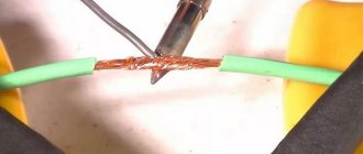
The signal from USB to the device is transmitted using twisted pairs. The core (wire) is color-coded, which simplifies the repair process.
Colored wires in the USB connector
Making the pinout is very simple: you need to mirror the desired connector and solder the wires in accordance with the color.
The main players are positive and negative contacts. Take any adapter with 5V, cut off the USB connector with a utility knife. Then you need to strip and tin the wires. For the connector, the same manipulations. Then soldering occurs according to the scheme. Each connection is wrapped with electrical tape, then they are connected to each other with hot-melt adhesive.
In USB 2.0 wiring there are only 4 shielded wires arranged linearly: two for power (first and last) and two for data transfer (second and third). They are marked as follows:
- +5V (power) is responsible for power supply.
- -D: data transfer.
- +D: Same as -D.
- GND (ground) – for grounding. Denoted by an inverted T.
USB Type A pinout
Despite the same circuits, USB types A and B have differences: In A, the arrangement of connectors is linear (from the first to the fourth), while in B, it is top and bottom:
| Top | Bottom |
| First | Third |
| Second | Fourth |
USB type B pinout
USB 3.0 has 5 additional connectors to match USB 2.0.
USB 3.0 pinout
Characteristics of 5 additional wires:
- the fifth works to receive information with a minus sign;
- the sixth is also for Data, only for +;
- seventh – grounding;
- the eighth and ninth are for data transmission (+ and -, respectively).
The USB 3.0 specification stands out among its predecessors not only in its high speed, but also in energy savings. This happens due to the function of the interrogation interface of the connected device, as well as a reduction in power in standby mode.
Micro USB connector pinout
To begin with, we present the wiring for this specification.
Micro USB v 2.0 connector wiring
As can be seen from the figure, this is a 5 pin connection; both the plug (A) and socket (B) have four contacts. Their purpose and digital and color designation correspond to the accepted standard, which was given above.
Description of the micro USB connector for version 3.0.
For this connection, a characteristically shaped 10 pin connector is used. In fact, it consists of two parts of 5 pin each, and one of them fully corresponds to the previous version of the interface. This implementation is somewhat confusing, especially considering the incompatibility of these types. Probably, the developers planned to make it possible to work with connectors of earlier modifications, but subsequently abandoned this idea or have not yet implemented it.
MicroUSB connector layout for version 3.0
The figure shows the pinout of the plug (A) and the appearance of the micro USB socket (B).
Contacts 1 to 5 fully correspond to the second generation micro connector, the purpose of the other contacts is as follows:
- 6 and 7 – data transmission via high-speed protocol (SS_TX- and SS_TX+, respectively).
- 8 – mass for high-speed information channels.
- 9 and 10 – data reception via high-speed protocol (SS_RX- and SS_RX+, respectively).
How does it work?
First, let’s find out what OTG (On-The-Go) is on Wiki. The reality is:
Photo 8. Device, how OTG USB data cable is made
The microUSB connector has 5 antennae-contacts, but on the other hand, for some reason, there are only 4 pins for soldering wires. According to the theory, the 4th and 5th pins must be closed in order for the device on this side to become the leading one (active, master, host) and a test with a multimeter confirms that this is the case. But where is this implemented? Apparently, somewhere inside (see where the arrow points in Photo 8), and this was obviously done during the production of the connector itself.
We take another microUSB connector, which is “regular”, and disassemble it:
Photo 9. What's inside the microUSB connector
Again, there are only 4 pins for soldering wires, and pin #4 is physically present in the form of an antenna contact, but... how to use it? Turn it over and see:
Photo 10. Design of a regular microUSB connector
This is where it got lost (literally ended), this 4th conclusion. That is, to make this connector one that is needed for OTG, you need to close the 4th and 5th pins here. But to do this, the connector will have to be disassembled, and as you can see in Photos 9 and 10, I couldn’t do this without unscrewing it... but in general it is dismountable [bought here, Aliexpress], theoretically it can be taken apart carefully.
If on one side there is a regular microUSB male connector (with the fourth pin “hanging in the air”), and on the other there is also a microUSB male connector, but with pin No. 4 shorted to ground,
then we have an OTG cable that allows you to connect two smartphones. One of them becomes the host, the other becomes the slave. Further, their behavior and interaction should be the same as in the case of connecting a smartphone via USB to a desktop computer.
Mini USB pinout
This connection option is used only in early versions of the interface; in the third generation this type is not used.
Mini USB connector pinout
As you can see, the wiring of the plug and socket is almost identical to the micro USB, respectively, the color scheme of the wires and the contact numbers are also the same. Actually, the differences are only in shape and size.
Sources used:
- https://infotechnica.ru/pro-sborku-i-podklyucheniya/usb-razemyi-peredney-paneli-k-materinskoy-plate/
- https://prohelps.ru/raspinovka-usb-na-materinskoy-plate/
- https://compconfig.ru/winset/kak-otklyuchit-ili-vklyuchit-usb-portyi-v-windows.html
- https://odinelectric.ru/wiring/wires/shema-raspinovki-usb-kabelya-po-tsvetam
- https://www.asutpp.ru/raspinovka-usb.html
SHARE Facebook
- tweet
Previous articleHow to share Wi-Fi password on iPhone: you might not know it
Next articleTwo weeks with Android Auto behind the wheel. Impressions - AndroidInsider.ru