Fixed Base Current Bias Circuit
The simplest bias circuit uses a base bias resistor between the base and the base battery Vbias. Using an existing Vpit source instead of a new bias source is very convenient. An example of this bias circuit is shown in the audio amplifier stage of a detector receiver in the RF Circuits section of Chapter 9. Note the resistor between the base and battery terminal. A similar diagram is shown in the figure below.
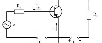
Write the equation of Kirchhoff's voltage law for a circuit that includes a battery, RB and the voltage drop VBE across the transistor junction in the figure below. Please note that we use the notation Voffset, although in fact it is Vpit. If the coefficient β is large, we can make the approximation that IK = IE. For silicon transistors VBE ≅ 0.7 V.
Fixed Base Current Bias Circuit
\[V_{offset} - I_B R_B - V_{BE} = 0\]
\[V_{offset} - V_{BE} = I_B R_B\]
\[I_B = { V_{offset} - V_{BE} \over R_B }\]
\[I_E = (\beta + 1)I_B \approx \beta I_B\]
\[I_E = { V_{displacement} - V_{BE} \over R_B / \beta }\]
The β coefficient of small-signal transistors is typically in the range of 100–300. Assuming we have a β=100 transistor, what value of base bias resistor would be required to achieve 1mA emitter current?
Solving the IE equation to determine RB and substituting the values of β, Voffset, VBE and IE will give the result 930 kOhm. The closest standard value is 910 kOhm.
\(\beta = 100 \qquad V_{offset} = 10 V \qquad I_K \approx I_E = 1 mA \)
\[R_B = { V_{offset} - V_{BE} \over I_E / \beta } = { 10 - 0.7 \over 1 mA / 100 } = 930 kOhm \]
What will be the emitter current with a 910 kOhm resistor? What happens to the emitter current if we replace the transistor with a random one with β=300?
\(\beta = 100 \qquad V_{offset} = 10 V \qquad R_B = 910 kOhm \qquad V_{BE} = 0.7 V\)
\[I_E = { V_{offset} - V_{BE} \over R_B / \beta } = { 10 - 0.7 \over 910 kOhm / 100 } = 1.02 mA \]
\(\beta = 300\)
\[I_E = { 10 - 0.7 \over 910 kOhm / 300 } = 3.07 mA \]
When using a standard 910 kOhm resistor, the emitter current will change slightly. However, when β changes from 100 to 300, the emitter current triples. This is unacceptable for a power amplifier if we expect the collector voltage to vary from near Vsupply to near ground. However, for low level signals from microvolts to about a volt, the bias point can be centered at β equal to the square root of (100 300), which is equal to 173. The bias point will still drift over a significant range. However, low level signals will not be clipped.
A fixed base current bias circuit is inherently unsuitable for the large emitter currents used in power amplifiers. The emitter current in a bias circuit with a fixed base current is not temperature stable. Temperature runaway is the result of high emitter current, which causes an increase in temperature, which causes an increase in emitter current, which will further increase the temperature.
The principle of operation of a bipolar transistor
Now we will try to figure out how a transistor works. I will not go into details of the internal structure of transistors as this information will only confuse. Better take a look at this drawing.
This image best explains the working principle of a transistor. In this image, a person controls the collector current using a rheostat. He looks at the base current; if the base current increases, then the person also increases the collector current, taking into account the gain of the transistor h21E. If the base current drops, then the collector current will also decrease - the person will correct it using a rheostat.
This analogy has nothing to do with the actual operation of a transistor, but it makes it easier to understand the principles of its operation.
For transistors, rules can be noted to help make things easier to understand. (These rules are taken from the book “The Art of Circuit Design” by P. Horowitz W. Hill).
- The collector has a more positive potential than the emitter
- As I already said, the base-collector and base-emitter circuits work like diodes
- Each transistor is characterized by limiting values such as collector current, base current and collector-emitter voltage.
- If rules 1-3 are followed, then the collector current Ik is directly proportional to the base current Ib. This relationship can be written as a formula.
From this formula we can express the main property of a transistor - a small base current controls a large collector current.
- current gain.
It is also denoted as
Based on the above, the transistor can operate in four modes:
- Transistor cutoff mode - in this mode, the base-emitter junction is closed, this can happen when the base-emitter voltage is insufficient. As a result, there is no base current and therefore there will be no collector current either.
- The active mode of the transistor is the normal mode of operation of the transistor. In this mode, the base-emitter voltage is sufficient to cause the base-emitter junction to open. The base current is sufficient and the collector current is also available. The collector current is equal to the base current multiplied by the gain.
- Transistor saturation mode - the transistor enters this mode when the base current becomes so large that the power of the power source is simply not enough to further increase the collector current. In this mode, the collector current cannot increase following an increase in the base current.
- Inverse transistor mode - this mode is used extremely rarely. In this mode, the collector and emitter of the transistor are swapped. As a result of such manipulations, the gain of the transistor suffers greatly. The transistor was not originally designed to operate in such a special mode.
To understand how a transistor works, you need to look at specific circuit examples, so let's look at some of them.
Transistor in switch mode
A transistor in switch mode is one of the cases of transistor circuits with a common emitter. The transistor circuit in switching mode is used very often. This transistor circuit is used, for example, when it is necessary to control a powerful load using a microcontroller. The controller leg is not capable of pulling a powerful load, but the transistor can. It turns out that the controller controls the transistor, and the transistor controls a powerful load. Well, first things first.
The main idea of this mode is that the base current controls the collector current. Moreover, the collector current is much greater than the base current. Here you can see with the naked eye that the current signal is amplified. This amplification is carried out using the energy of the power source.
The figure shows a diagram of the operation of a transistor in switching mode.
For transistor circuits, voltages do not play a big role, only currents matter. Therefore, if the ratio of the collector current to the base current is less than the gain of the transistor, then everything is okay.
In this case, even if we have a voltage of 5 volts applied to the base and 500 volts in the collector circuit, then nothing bad will happen, the transistor will obediently switch the high-voltage load.
The main thing is that these voltages do not exceed the limit values for a specific transistor (set in the transistor characteristics).
Well, now let's try to calculate the value of the base resistor.
As far as we know, the current value is a characteristic of the load.
Those. I=U/R
We don't know the resistance of the light bulb, but we know the operating current of the light bulb is 100 mA. In order for the transistor to open and allow such current to flow, you need to select the appropriate base current. We can adjust the base current by changing the value of the base resistor.
Since the minimum value of the transistor gain is 10, then for the transistor to open, the base current must become 10 mA.
The current we need is known. The voltage across the base resistor will be This voltage value across the resistor is due to the fact that 0.6V-0.7V is dropped at the base-emitter junction and we must not forget to take this into account.
As a result, we can easily find the resistance of the resistor
All that remains is to choose a specific value from a number of resistors and it’s done.
Now you probably think that the transistor switch will work as it should? That when the base resistor is connected to +5 V the light bulb lights up, when it is turned off the light bulb goes out? The answer may or may not be yes.
The thing is that there is a small nuance here.
The light bulb will go out when the resistor potential is equal to the ground potential. If the resistor is simply disconnected from the voltage source, then everything is not so simple. The voltage on the base resistor can miraculously arise as a result of interference or some other otherworldly evil spirit