Algorithm for calculating stabilizer power
When selecting the required voltage stabilizer model, its incorrectly calculated power can lead to the following consequences:
- a stabilizer with an output power less than required will constantly turn off or not start at all, and possibly fail;
- purchasing a device with a power much higher than the required value will be a waste of money. The device will be underloaded during operation, which will reduce its efficiency.
To determine the current stabilizer power and correctly select the appropriate model, we recommend following an algorithm consisting of three steps:
- Find out the load power.
- Add the margin to the value of the power consumed by the load.
- Select a suitable stabilizer model based on the final value.
Let's look at the three points mentioned above and analyze the most common mistakes that accompany each of them.
Subcategories of stabilizers
There are different types of stabilizing devices with different types of operation. Let's look at the main stabilizers to make your choice easier in the retail chain.
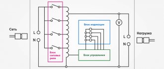
Relay
With an increased speed of regulation, strong voltage surges, several times over a short period, the stabilizers work with low accuracy and can make clicking noises during operation. This is a relay that switches the stages of the transformer.
Thyristor
Such devices are also called triac devices. They belong to electronic devices. Their increased accuracy and speed of supply voltage regulation, quiet operation attracts buyers when purchasing.
Among the shortcomings, various microsecond dips during switching can be noted. However, even at an increased cost, they are quite suitable for home use. Most often, manufacturers provide extended long-term warranties for such devices.
Electromechanical
These types of devices include: servo-driven, roller, brush, and electrodynamic devices. They have increased control accuracy, no noise during operation, and no gradual change in voltage during input power fluctuations.
One of the disadvantages is the rapid wear of the brush assembly due to increased sparking under significant load. Electrodynamic voltage stabilizers, roller ones from Ortea, do not have such disadvantages. They are the best choice for a private home.
Find out the power connected to the load stabilizer
The load power is equal to the sum of the powers of all devices connected to the stabilizer. Before calculating the total power value, it is necessary to find out the energy consumption of each consumer. This is very simple to do: the power of electrical appliances is usually indicated in the technical documentation and is duplicated on the nameplate attached to the product.
Despite the apparent simplicity of the action, at this stage you can make several serious mistakes, which will entail choosing a stabilizer that is not suitable for your tasks.
Particular attention should be paid to equipment for which several capacities are indicated: pumps, heating, sound, climate control equipment, etc. It is important to distinguish between electrical power and the power produced by the product when performing its direct tasks, for example, thermal power for heating boilers, cooling power for air conditioners, sound power for audio systems.
Note!
When choosing a stabilizer, you should rely solely on the amount of power consumed by the load from the mains! In the passport of an electrical appliance, this parameter may be called: “power consumption”, “connecting power”, “electric power”, etc. All of the above is a reflection of one quantity - active power, which is measured in Watts (W or W).
Note!
Manufacturers of stabilizers usually build their range of stabilizers based on another quantity - total power, which is measured in Volt-Amps (VA or VA). It is important to understand that Watts and Volt-Amps are not the same thing, and therefore 1000 W is not equal to 1000 VA!
For electrical appliances that contain capacitive components or electric motors, the active and apparent power can vary significantly. Therefore, purchasing a stabilizer designed for 1000 VA with a load of 1000 W may be the wrong decision - the device will be overloaded with all the ensuing consequences.
To avoid this error, you should convert Watts to Volt-Amps and analyze not only the active, but also the total load power. Conversion from Watts to Volt-Amps is carried out by dividing the value in Watts by a special parameter - power factor or cos(φ): VA=W/cos(φ).
Cos(φ) reflects the dependence of the active power of the device on the total. The closer the cos(φ) value is to unity, the less energy is dissipated in the form of electromagnetic radiation and the more is converted into useful work.
The numerical value of cos(φ) is usually (but not always) indicated in the technical documentation of the device consuming alternating current (may be designated as “cos(φ)”, “Power Factor” or “PF”). If the manufacturer has not provided information about the power factor of its product, then for household appliances it is acceptable to take cos(φ) in the range of 0.7-0.8, except for devices that convert electricity into light and heat (incandescent lamps, electric kettles, irons, etc.). etc.), for them the range of power factor values is 0.9-1.
Modern technology, primarily computers, is often equipped with a power supply with power factor correction, which brings this parameter closer to unity - 0.95-0.99. If there is no confidence in the presence of such a function (denoted “PFC” or “KKM”), then for cos(φ) it is recommended to use the value from the typical range indicated in the previous paragraph.
The total load power should be calculated using only the power factor of the equipment corresponding to that load, and not using the input power factor of the stabilizer!
Note!
Devices that have an electric motor in their design are characterized by high starting currents. This category includes: pumps, washing machines and dishwashers, refrigerators, air conditioners, machine tools and compressors. The amount of energy consumed from the electrical network at the moment of turning on any of the above-mentioned devices can be several times higher than the value characteristic of the nominal operating mode.
Manufacturers of this equipment sometimes list the maximum power consumption directly in the characteristics of each model, and sometimes vice versa - they give only the nominal power value, trying not to draw attention to inevitable current surges. We recommend that you carefully study the documentation accompanying any equipment and look for information about the actual power consumed by the device during startup and in various operating modes. The load power is determined using the highest value given for each device!
In addition to mechanisms with electric motors, high starting currents are also typical for lighting devices. And not only with halogen and incandescent lamps, but also with the recently popular LED lamps. LEDs do not have inrush currents, but most luminaires based on them are equipped with capacitors, the inclusion of which causes a sharp increase in current consumption.
When choosing a stabilizer to protect a large lighting system, it should be taken into account that the power value that occurs when such a system is started can be many times higher than the rated value.
Types of voltage stabilizers
Another important point of choice is the type of stabilizer, depending on the principle of voltage equalization. In great detail what types of stabilizers there are, all the pros and cons, a video comparison of their work, can be found in the article Types of voltage stabilizers .
- relay
- thyristor-triac
- servo-driven
- inverter
The most common models at the moment are relay and thyristor (or triac). Relay - because of their low cost, thyristor - because of the quality of voltage equalization and low noise operation.
Servo drives are less common, mostly Chinese models. Their service life leaves much to be desired - up to 5 years.
Well, due to their high cost, inverter models are rarely found in a wide range, although they have the best qualities among all other models. Another disadvantage is that they are designed mainly for light loads.
When choosing triacs, pay attention to the number of control stages. The more there are, the smoother the voltage equalization occurs.
Most have 12 steps - it is not advisable to take less, since the blinking of the lighting bulbs will be very noticeable when switching.
And the fewer the steps, the greater the error at the output. For stabilizers with 9 levels of equalization, the error reaches 15 Volts.
- 9 steps - 15V error
- 12 steps - error 10-12V
- 16 steps - 6V error
- 36 steps - 3V error
More expensive models have 16 and 32 steps. Usually they are not found in stock, only on order. But they are better suited for protecting expensive electronic equipment.
Here is a table of some popular brands of stabilizers often found in our stores and their prices:
You can view current prices today and choose the model you need here.
Next, you can watch a video review of each of the brands presented in the table:
Adding power reserve
A properly selected stabilizer should have an output power that exceeds the power required to power the load. The difference between the stabilizer power and the actual power consumption of the load is called power reserve.
The recommended margin is 30% of the load energy consumption. This value will allow:
- connect additional devices to the device during operation, the power of which was not taken into account in the initial load calculation;
- avoid overload in the event of a strong voltage drop in the electrical network.
Let us give an explanation on the second point. The fact is that the power of the stabilizer decreases when the supply voltage leaves certain limits (operating range). In particular, at 135 V in the network, instead of the declared 500 VA, the stabilizer will produce only 400 VA and, accordingly, will not be able to power the maximum load relative to its rating.
For some equipment, it is recommended to provide a power reserve of over 30%. These are, for example, air conditioners or IT equipment. In the first case, this decision is explained by an increase in the power consumed by the air conditioner during operation of the device (caused by the inevitable contamination of the filter mesh). In the second case, there is a tendency towards a constant increase in the capacity of telecommunications equipment.
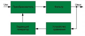
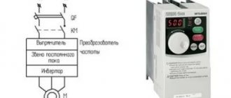
Stabilizer calculation
Stabilizer calculationTo obtain a more constant voltage across the load when the current consumed changes, a stabilizer is connected to the output of the rectifier, which can be made according to the circuit shown in Fig. 1. This device uses zener diode V5
and control transistor
V6
.
The calculation will allow you to select all elements of the stabilizer based on the specified output voltage Un
and maximum load current
In
. However, both of these parameters should not exceed the parameters of the already calculated rectifier. And if this condition is violated, then the stabilizer is first calculated, and then the rectifier and power transformer. The stabilizer is calculated in the following order.
(Uvyp) required for the stabilizer to operate.
at a given output
(Un)
:
Uvyp = Un + 3
,
- Here, number 3, which characterizes the minimum voltage between the collector and emitter of the transistor, is taken based on the use of both silicon and germanium transistors. If the stabilizer is connected to a ready-made or already calculated rectifier, in further calculations it is necessary to use the real value of the rectified voltage Uvyp
.
2. Calculate the maximum power dissipated by the transistor:
Pmax = 1.3 (Uvyp - Un) In
,
3. Select a control transistor. Its maximum permissible power dissipation must be greater than the Pmax
, the maximum permissible voltage between the emitter and the collector is greater than
Uvyp
, and the maximum permissible collector current is greater than
In
.
4. Determine the maximum base current of the regulating transistor:
Ib.max = In / h21E min
,
- where: h21Emin is the minimum current transfer coefficient of the selected (according to the reference book) transistor.
.
5. Select a suitable zener diode. Its stabilization voltage must be equal to the output voltage of the stabilizer, and the value of the maximum stabilization current must exceed the maximum base current Ib max
.
6. Calculate the resistance of resistor R1
:
R1 = (Uvyp - Ust) / (Ib max + Ist min)
,
- Here R1 is the resistance of resistor R1, Ohm; Ust — zener diode stabilization voltage, V; Ib.max - calculated value of the maximum base current of the transistor, mA; Ist.min is the minimum stabilization current for a given zener diode, indicated in the reference book (usually 3...5 mA).
.
7. Determine the power dissipation of resistor R1
:
PR1 = (Uvyp - Ust)2 / R1
,
It may happen that a low-power zener diode is not suitable for the maximum stabilization current and you will have to choose a zener diode of significantly higher power - this happens with high consumption currents and using a transistor with a low h21E
.
In this case, it is advisable to introduce an additional low-power transistor V7
(Fig. 2), which will reduce the maximum load current for the zener diode (and therefore the stabilization current) by approximately
h21E
times and, accordingly, use a low-power zener diode.
The calculations presented here do not correct for changes in mains voltage, and also omit some other clarifications that complicate the calculations. It is easier to test the assembled stabilizer in action by changing its input voltage (or mains voltage) by ± 10% and more accurately select resistor R1 based on the greatest stability of the output voltage at maximum load current. Source: shems.h1.ru
Selecting the stabilizer model
To determine the model that is suitable for power, it is necessary to compare the power range of stabilizers offered by the manufacturer with the energy consumption of the load - the nearest higher value in the power range will be the required power of the stabilizer.
Note!
Selecting a stabilizer with a power value that is closest to the power consumption of the load on the downside will either reduce the previously established power reserve, or in the worst case, will lead to the purchase of a stabilizer with output parameters that do not correspond to the load.
Note!
For a three-phase stabilizer, the load on each phase should be no more than 1/3 of the rated one. For example, a three-phase stabilizer with a rating of 6000 VA will power a three-phase load of 4200 VA (the power consumed from one phase will be 1400 VA), but connecting this load stabilizer to a separate phase of 2500 VA will cause an overload, since the maximum permissible value for one phase is: 6000 /3=2000 VA.
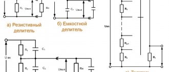
Calculation of a parametric stabilizer
To calculate operating parameters, use the following formulas:
- taking into account the voltage division, the potential difference on the individual components is determined as follows: Uin = Un + I*Rogr = Un + (Ist + In)*Rogr;
- to maintain a stable voltage, it is necessary to maintain the permissible current in accordance with the restrictions on the current-voltage characteristics (Imin, Imax);
- taking into account the noted principles, the rating of the limiting resistance is determined: Rogr = (Uin min – Ust min)/ (In max + Ist min);
- the functional range of the parametric stabilizer circuit is specified according to the permissible range of changes in the input voltage: ΔUin = Uin max – Uin min = Ust max + ((Ist max + In min) * Rogr – (Ust min + (In max + Ist min) * Rogr) ;
- to simplify, you can apply a mathematical transformation of the formula: ΔUin = (Ust max – Ust min) + (Ist max – Ist min) * Rogr – (In max – In min) * Rogr;
- taking into account the division made: ΔUin = ΔUst + ΔIst * R limit + ΔIn * R limit;
- if the current in the load does not change: ΔUin = ΔIst * R limit;
- The energy efficiency of the created device can be calculated taking into account losses: Efficiency = (Ust*In)/(Uin * Iin) = (Ust/Uin)/(1+Ist/In).
For your information. The last formula explains the increase in energy costs as the difference between the input and output voltage increases. A similar condition is met when a larger current passes through a semiconductor device.
The initial data is determined by the parameters of the power source (load). In accordance with the calculation results, a suitable limiting resistor and zener diode are selected. The components must be arranged in accordance with the diagram shown in the figure.
An example of selecting a stabilizer based on power
The stabilizer is purchased to simultaneously protect three single-phase consumers. We will not focus on the specific type of devices, let’s simply call them: consumer 1, consumer 2 and consumer 3.
According to factory data sheets:
- the rated power of consumer 1 is 600 W, consumer 2 – 130 W, consumer 3 – 700 W;
- The power factor of consumers 1 and 2 is 0.7, consumer 3 is 0.95.
Determine the load power. Let consumer 1 belong to the category of equipment characterized by the presence of high inrush currents. When calculating, we do not use its rated power, but the maximum starting power, equal to 1800 W according to the technical documentation. Using the above formula, we convert the power of each consumer from W to VA:
- 1800 / 0.7 = 2571.4 VA – for consumer 1;
- 130 / 0.7 = 185.7 VA – for consumer 2;
- 700 / 0.95 = 736.8 VA – for consumer 3.
Now let’s determine the total power consumption of the planned load in W and VA:
- 1800 + 130 + 700 = 2630 W;
- 2571.4 + 185.7 + 736.8 = 3493.9 VA.
We will make further selection of the stabilizer, taking into account that the total load power on the device will be 3493.9 VA, and the active one - 2630 W (note the difference in the values in W and VA).
Next, we determine the power reserve. Let us accept the recommended value of the power reserve as 30% of the load's energy consumption - to obtain the numerical value of the required reserve, we multiply the previously calculated total power of the planned load by 0.3:
- 2630 x 0.3 = 789 W – active power reserve;
- 34.939 x 0.3 = 1048.17 VA – full power reserve.
Therefore, the load power taking into account the reserve will be:
- 2630 + 789 = 3419 W;
- 3493.9 + 1048.17 = 4542.07 VA.
Now we will select single-phase stabilizer models with the required power to power our load (taking into account the reserve), using the standard power range of single-phase inverter stabilizers produced by Shtil Group of Companies:
| Apparent power, VA | Active power, W |
| 350 | 300 |
| 550 | 400 |
| 800 | 600 |
| 1000 | 800 |
| 1500 | 1125 |
| 2000 | 1500 |
| 2500 | 2000 |
| 3000 | 2500 |
| 3500 | 2750 |
| 5000 | 4500 |
| 7000 | 5500 |
| 8000 | 7200 |
| 10000 | 9000 |
| 12000 | 11000 |
| 15000 | 13500 |
| 20000 | 18000 |
The power closest to the calculated values is 5000 VA and 4500 W, therefore, this particular stabilizer is suitable for connecting consumer 1, consumer 2 and consumer 3.
Let's assume that consumer 1, consumer 2 and consumer 3 need to be connected not to a single-phase, but to a three-phase stabilizer. The standard power range of Shtil Group for such devices is as follows:
| Apparent power, VA | Active power, W |
| 6000 | 5400 |
| 10000 | 8000 |
| 15000 | 13500 |
| 20000 | 16000 |
A load with a total power of 4542.07 VA and an active power of 3419 W can be connected to one phase of a three-phase stabilizer with an output power of 15000 VA / 13500 W, in which a separate phase will produce a maximum of 5000 VA / 4500 W.
Load distribution, that is, connecting each consumer to a separate phase, will allow you to choose a less powerful stabilizer model. The greatest load will be on the phase feeding consumer 1, whose energy consumption is 1800 W / 2571.4 VA.
Let's calculate the 1 power reserve required by the consumer (let's take the recommended reserve value of 30%):
- 1800 x 0.3 = 540 W – active power reserve;
- 2571.4 x 0.3 = 771.4 VA – full power reserve;
- 1800 + 540 = 2340 W – active power of consumer 1 taking into account the reserve;
- 2571.4 + 771.4 = 3342.8 VA – total power of consumer 1 taking into account the reserve.
This means that the maximum possible load on one phase of the stabilizer, provided that three consumers are connected to different phases, can be: 3342.8 VA / 2340 W.
Let's choose a stabilizer model with an output power of 10000 VA / 8000 W, in which the permissible load per phase is approximately equal to 3333 VA / 2666 W. In this case, it is permissible to choose a stabilizer with a total power slightly less than the calculated one - in fact, this will reduce the power reserve for consumer 1 by 1-2%.
Note!
There are stabilizers with a “3 in 1” topology, that is, with a three-phase input and a single-phase output. Such a scheme allows you to evenly load a three-phase network when connecting a single-phase load.
More information about the model range of Shtil inverter stabilizers can be found by clicking on the link: Shtil inverter-type voltage stabilizers.
The simplest DC stabilizer
The semiconductor device in question is designed to stabilize the current at the required level, has a low cost and makes it possible to simplify the development of circuits for many electronic devices. I’ll try to fill in a little the lack of information about simple circuit solutions for DC stabilizers.
A little theory
An ideal current source has an infinitely large EMF and an infinitely large internal resistance, which makes it possible to obtain the required current in the circuit independent of the load resistance.
Conventional graphic designation of the current source:
Considering the theoretical assumptions about current source parameters helps to understand the definition of an ideal current source. The current produced by an ideal current source remains constant as the load resistance changes from short circuit to infinity. To maintain the current value unchanged, the value of the emf varies from a value not equal to zero to infinity. A property of a current source that allows you to obtain a stable current value: when the load resistance changes, the EMF of the current source changes in such a way that the current value remains constant.
Real current sources maintain current at a required level over a limited range of voltage produced across a load and a limited load resistance. An ideal source is considered, and a real current source can operate at zero load resistance. The mode of closing the output of the current source is not an exception or a difficult-to-implement function of the current source; it is one of the operating modes into which the device can painlessly switch if the output is accidentally shorted and switch to operating mode with a load resistance greater than zero.
A real current source is used in conjunction with a voltage source. 220 volt 50 Hz network, laboratory power supply, battery, gasoline generator, solar battery - voltage sources that supply electricity to the consumer. A current stabilizer is connected in series with one of them. The output of such a device is considered as a current source.
The simplest current stabilizer is a two-terminal component that limits the current flowing through it to the magnitude and accuracy corresponding to the manufacturer's data. Such a semiconductor device in most cases has a housing that resembles a low-power diode. Due to their external similarity and the presence of only two terminals, components of this class are often mentioned in the literature as diode current stabilizers. The internal circuit does not contain diodes; this name stuck only due to its external similarity.
Examples of diode current stabilizers
Diode current stabilizers are produced by many semiconductor manufacturers.
1N5296 Manufacturers: Microsemi and CDI
Stabilization current 0.91 mA ± 10% Minimum voltage at the terminals in stabilization mode 1.29 V Maximum pulse voltage 100 V
E-103 Manufacturer Semitec
Stabilization current 10 mA ± 10% Minimum voltage at the terminals in stabilization mode 4.2 V Maximum pulse voltage 50 V
L-2227 Manufacturer Semitec
Stabilization current 25 mA ± 10% Minimum voltage at the terminals in stabilization mode 4 V Maximum pulse voltage 50 V
From theory to practice
The use of diode current stabilizers simplifies electrical circuits and reduces the cost of devices. The use of diode current stabilizers is attractive not only for its simplicity, but also for increasing the stability of the devices being developed. One semiconductor of this class, depending on the type, provides current stabilization at a level from 0.22 to 30 milliamps. The names of these semiconductor devices according to GOST and circuit designations could not be found. In the diagrams of the article we had to use the designation of a conventional diode.
When connected to the LED power circuit, the diode stabilizer ensures the required mode and reliable operation. One of the features of the diode current stabilizer is operation in the voltage range from 1.8 to 100 volts, which allows you to protect the LED from failure when exposed to pulsed and long-term voltage changes. The brightness and shade of the LED glow depend on the current flowing. One diode current stabilizer can provide operation for several LEDs connected in series, as shown in the diagram.
This circuit is easy to convert depending on the LEDs and supply voltage. One or more parallel-connected diode current stabilizers in the LED circuit will set the LED current, and the number of LEDs depends on the range of supply voltage changes.
Using diode current sources, you can build an indicator or lighting device designed to be powered from direct voltage. Thanks to the power supply with a stable current, the light source will have a constant brightness even when the supply voltage fluctuates.
The use of a resistor in the LED circuit of the DC motor supply voltage indicator of a printed circuit board drilling machine led to rapid failure of the LED. The use of a diode current stabilizer made it possible to obtain reliable operation of the indicator. Diode current stabilizers can be connected in parallel. The required load power mode can be obtained by changing the type or turning on in parallel the required number of these devices.
When powering an LED, optocouplers through a resistor supply voltage ripple of the circuit lead to brightness fluctuations superimposed on the front of the rectangular pulse. The use of a diode current stabilizer in the power supply circuit of the LED, which is part of the optocoupler, makes it possible to reduce the distortion of the digital signal transmitted through the optocoupler and increase the reliability of the information channel.
The use of a diode current stabilizer that sets the operating mode of the zener diode makes it possible to develop a simple reference voltage source. When the supply current changes by 10 percent, the voltage on the zener diode changes by 0.2 percent, and since the current is stable, the value of the reference voltage is stable when other factors change.
The effect of supply voltage ripple on the output reference voltage is reduced by 100 decibels.
Internal circuit
The current-voltage characteristic helps to understand the operation of a diode current stabilizer. The stabilization mode begins when the voltage at the device terminals exceeds about two volts. At voltages greater than 100 volts, breakdown occurs. The actual stabilization current may deviate from the rated current by up to ten percent. When the voltage changes from 2 to 100 volts, the stabilization current changes by 5 percent. Diode current stabilizers produced by some manufacturers change the stabilization current when the voltage changes by up to 20 percent. The higher the stabilization current, the greater the deviation as the voltage increases. Parallel connection of five devices designed for a current of 2 milliamps allows one to obtain higher parameters than one rated at 10 milliamps. Since the minimum current stabilization voltage decreases, the voltage range in which the stabilizer operates increases.
Let's sum it up
To avoid mistakes when determining the power of the stabilizer and wasting money on a device that will ultimately turn out to be useless, you must:
- when calculating the load power, use the value of the power consumed by the electrical appliance from the network, and not the value of the power characterizing the useful operation of this electrical appliance;
- when calculating the total load power, use the power factor corresponding to this load, and not the input power factor of the stabilizer;
- calculate the load power with mandatory consideration of starting currents for all devices characterized by their high value;
- if necessary, convert W to VA and analyze the load power in units of measurement corresponding to the units on the basis of which the power range of stabilizers is built;
- select the stabilizer power taking into account the required reserve;
- choose a stabilizer with a rated power higher than the calculated load power (only a slight rounding of the load power downwards is acceptable, provided there is a pre-established power reserve);
- choose a three-phase stabilizer for a single-phase load, analyzing not only the rated output power of the device, but also the power of an individual phase.
Carefulness in calculations and compliance with all the above rules will help you choose a stabilizer model that meets the requirements of your load. In case of any difficulties or questions, we recommend that you consult with specialists!
When calculating power, it is worth mentioning such important definitions as “cos φ” and “starting currents”
So what is "cos φ"?
This indicator reflects the ratio of active power to total power. The name of any voltage stabilizer model contains numbers, for example, ENERGY Ultra 20000, they show the power in Volts / Amperes (20000 V / A). Everyone is accustomed to measuring power consumption in Watts, and this is where the need to use the cosφ value arises. If the stabilizer mainly works with heating elements, an electric stove, a kettle, a heating element, light sources (only active load), then the cosφ angle value is 1. Conversion formula: Watts = V/A x cosφ (1). Let's consider the Energy ASN 8000 device in practice:
8000 VA x 1 = 8 kW.
If the stabilizer is mainly connected to equipment with electric motors, pumps and compressors (active/reactive load), then in this case cosφ will be equal to 0.8 or 0.7. It depends on the specific case (it is better to use an indicator of 0.7). Energy HYBRID SNVT 5000 has a total power of 5000 V/A. To understand how much this model can produce, you need 5000 (V/A) x 0.7 = 3.5 kW. If you have equipment connected to both heating elements and motors, then cosφ should be taken as 0.8.
What are inrush currents?
If the design of the equipment contains an electric motor, pump or compressor (refrigerator, washing machine, microwave oven, circulation and submersible pump, vacuum cleaner), then when such equipment is turned on, these devices consume power 3 to 7 times more than their nominal value. As soon as the electric motor reaches operating speed, its power consumption will be equal to the nominal value. Inrush currents last a maximum of a few seconds, but they cannot be neglected when calculating the total power of equipment in the room. For example, a refrigerator consumes 300 W during operation, and when the compressor starts up, its power increases to 1 kW. This means that the power of the refrigerator should be calculated not according to the nominal value, but taking into account the starting currents.
Types of installation and fastening
All stabilizers for the home can be classified as either floor or wall-mounted; there are also devices that are universal in installation method, which, depending on the characteristics of the room in which they are planned to be placed, can either be hung on the wall or mounted on the floor.
The most rational location can be considered wall-mounted, since, in addition to the obviously more compact method of installing it, this option practically eliminates the possibility of mechanical damage. The installation process itself on the wall is not difficult at all - to do this, you just need to screw in two dowels and fix the device on them.
Floor placement is more typical for three-phase models, which are massive and heavy. Floor stabilizers, both single-phase and three-phase, are widely used to regulate voltage throughout the entire home network, and wall stabilizers can either serve this purpose or be intended to serve specific electrical appliances or a group of them.
Among the most popular models, it should be noted such brands as ZORD, STIHL, ENERGY, RUSELF. Models of domestic production, CIS countries, many models of Chinese production, as well as European assembly are widely represented on the market. Often, the price of similar models from different manufacturers can fluctuate greatly, but the main determining factor should be the reliability of the device , for which the manufacturer’s reputation plays a significant role.
Also popular for home use are portable, compact devices that are designed to connect single, most vulnerable devices. Their range on the market is also very large and choosing a model that meets the requirements and at an affordable price is not a problem.