One of the main disadvantages of asynchronous motors is the difficulty of adjusting the rotation speed. It can be changed in three ways: changing the number of pole pairs, changing the slip and changing the frequency. Recently, to regulate the rotation speed of an asynchronous squirrel-cage motor, the current frequency is changed using frequency converters for the electric motor.
The concept of the operating principle of a frequency generator
Recently, high-frequency devices have become widely used in production; many inexperienced beginners who encounter them in practice often have the question of what a frequency converter is and what it is needed for. The advantages of a frequency drive for an electric motor are:
- reduction of engine power consumption;
- improved performance: smooth start-up and rotation speed adjustment;
- eliminating possible overloads.
Smooth starting is ensured by the converter due to its reduction of the starting current, which without a frequency converter exceeds the rated current by 5–7 times.
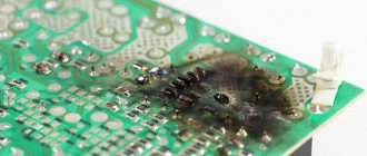
The main parts in the converter device are the inverter and capacitors. The inverter is usually made of diode bridges. Its task is to rectify the input voltage, which can take a value of 220V or 380V depending on the number of phases, but maintain ripple. Then the capacitors smooth out and filter the rectified voltage.
Then the direct current is sent to the microcircuits and output bridge IGBT switches. Typically, a bridge IGBT switch consists of six transistors connected in a bridge circuit. Protection against reverse polarity voltage breakdown is provided by diodes. In earlier circuits, thyristors were used instead of transistors, the significant disadvantages of which were some slowness in operation and interference.
Thanks to these devices, a pulse width sequence occurs with the required frequency. At the output of the frequency converter, the voltage pulses have a rectangular shape. And after they pass through the stator winding, due to its inductance, they take on a sinusoidal form.
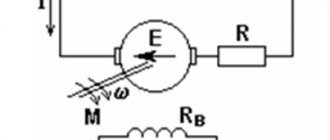
To understand why an inverter is needed, you need to understand that current can be constant and alternating. And if frequency converters are used when working with alternating current, then a direct current electric drive is required to control a direct current electric motor. It is called an inverter and its purpose in the circuit is to control the excitation current. And it can also maintain the rotor rotation speed within the required limits and perform its braking, regardless of load changes.
How to choose a frequency converter?
Frequency converters make it easy to change the engine speed and make its operation smoother. This increases the efficiency of the equipment and extends its service life.
What are frequency converters
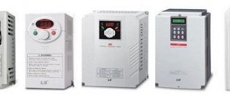
Frequency converters are devices that allow you to change the frequency of the output voltage. This is necessary in order to vary the engine speed.
When directly connected to the mains, the oscillation frequency remains unchanged, standard values are 50 or 60 Hz. Using a frequency converter allows you to increase or decrease the rotor rotation. The range of possible changes is from 0.5-800 Hz. However, now most motors are designed for a frequency of no more than 400 Hz.
Main features of converters
Modern electrical equipment is high-tech devices with program control. The electronic control system is responsible for accuracy and reliability. The units are quite compact and easy to operate.
Depending on whether the output voltage can be adjusted, converters are divided into controlled and uncontrolled. In the first, the parameters can be changed, in the second, the indicators are set by the design of the unit. There are also models where automatic tuning takes place to the parameters of the connected motor. To do this, you need to perform an identification start, during which the winding parameters are automatically determined.
In addition to the ability to adjust indicators, there are different types of device control. There are two of them: scalar and vector. Scalar does not give a chance to set precise settings; it only determines the ratio of the frequencies at the input and output. When the input data changes, the final parameters change proportionally. Vector control makes it possible to set the exact parameters required for a specific engine in a specific situation.
To make the equipment operate more accurately and control easier, modern equipment is equipped with memory cards and a display to display information.
When using converters, it is necessary to take into account some nuances. Thus, running the engine at low speeds leads to an increase in temperature, which the built-in fan may not be able to cope with. Therefore, it is necessary to monitor the heating and, if necessary, use forced cooling.
Also, a working converter becomes a powerful source of high-frequency current. The equipment's own microcircuits are protected from interference by special filters. But to prevent vibrations from affecting the operation of other devices, you need to use a shielding cable of as short a length as possible. The distance to other cables must be at least 10 cm. If there is a need to cross, this must be done at an angle of 90°.
Application of frequency converters
Frequency converters are connected to equipment whose operation involves changing the speed of the motor.
Such mechanisms include:
- pumps;
- ventilation systems;
- conveyors;
- compressors;
- manipulators and excavators;
- elevators;
- centrifuges;
- robotics, etc.
Also, a frequency converter is used to synchronize the operation of interconnected mechanisms. The dependence can be both direct and inverse.
Principle of operation
To ensure that the voltage passing through the converter changes its characteristics, the principle of double change is used. At the input, the mains voltage is rectified using a diode bridge and filtered by capacitors. Here the amplitude of the oscillations is smoothed out, after which the current flows into the converting part.
The conversion occurs thanks to transistors combined in a certain way (usually there are 6 of them). They are connected in a back-to-back circuit. With their help, the required indicators of the frequency and amplitude of current oscillations are set.
There are two types of control system:
- amplitude, when the input voltage indicators are regulated;
- pulse width (PWM), in which changes in indicators are affected by the order of switching transistors. In a certain, strictly defined order, the signal arrives at the positive and negative terminals, resulting in a sinusoid with clearly defined parameters.
The process is controlled and the specified characteristics are changed using microprocessors. A special microcontroller sends a signal to the microcircuit. The changes are compared with a given standard (5 Hz). Next, the program, using a special algorithm, converts the current to the required value. In addition, the microcontroller monitors the temperature of semiconductors, protects the device from overheating and sudden voltage surges.
Tips for choosing frequencies
When choosing a frequency generator, the lowest cost is determined by a set of minimal functions. The increase in value is proportional to their increase.
Initially, converters are classified by power . No less important parameters are the overload capacity and type of execution.
The power of the frequency generator must be no less than the maximum power of the installation. For prompt repair or replacement in the event of a breakdown of the frequency drive for the electric motor, it is advisable that the service center be located in close proximity.
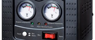
When choosing a converter, an important factor is its voltage. If you select a frequency generator of a certain voltage, and in the network it turns out to be lower, then it will turn off. If the network voltage remains within the permissible voltage for a long time, this will lead to its damage and the impossibility of further operation. Taking these risks into account, it is necessary to select frequency generators with a large permissible voltage range.
There are two types of converter control: vector and scalar.
With scalar control, constancy is maintained between the value of voltage and frequency at the output. This is the simplest type of frequency generators, and, as a result, cheaper.
With vector control, due to the reduction in static error, control is carried out more accurately. But the cost of an asynchronous frequency converter with this type of control is higher in comparison with scalar control.
The current frequency regulation zone must be within the required limits. For ranges with frequency adjustment greater than 10 times, it is better to choose vector control.
The number of inputs must be optimal, because if their number is too large, the price of the device for changing the frequency will be unreasonably high, and some difficulties may arise when setting it up.
It is necessary to take into account the overload capabilities of the frequency converter in terms of current and power. The current of the frequency converter should be slightly greater than the rated current of the motor. In the event of shock loads, a reserve for peak current is required, which must be at least 10% of the shock current.
Recommendations for choosing frequency converters for controlling asynchronous electric motors
To ensure reliable and long-term operation of the frequency converter, it is necessary to select the equipment correctly.
Initial information: load type, motor rated current, supply voltage, environmental conditions, EMC requirements, need for fast braking, speed/torque accuracy, converter control method.
Result: Frequency converter type, for example VACON NXS 00455 F2H1 SSS A1A2000000.
Selecting the load type.
The most common 2 types of loads:
- with a constant load moment (“PM”) in the operating speed range (conveyors, elevators, extruders, etc.). This type of load is characterized by overloads of up to 10...50%.
- with quadratic load moment (“KM”) in the operating speed range (pumps, fans, vane compressors). For this type of units, overloads of no more than 10% are typical. Due to the fact that there are no overloads in units with a quadratic load moment, it is possible to install inverters of a lower rating on these units.
Determination of the rated motor current and supply voltage.
The information is contained on the engine nameplate.
Selecting the power of the frequency converter.
First, the rated output current of the inverter is determined. It must be equal to or may exceed the rated current of the motor. If the frequency converter is designed for an asynchronous motor that has been in operation for many years, it is recommended to choose an inverter with a deliberately higher output current.
Environmental conditions.
The presence of dust and humidity determine the degree of protection (IP) of the converter:
- IP00
- IP20
- IP21
- IP54
If frequency converters are operated in conditions of high humidity and aggressive environments, Vacon recommends the use of varnished boards for additional protection of the drive.
Electromagnetic compatibility (EMC) requirements.
All Vacon frequency converters are manufactured with a built-in EMC filter, which allows them to comply with all global and Russian electromagnetic compatibility requirements and standards for industrial applications.
The need for quick braking.
Determined by the presence or absence of a brake chopper and a brake resistor. To reduce the rotation speed of the electric motor to zero, three methods are used: coasting braking, dumping energy into the braking resistor and returning braking energy to the network (recuperation).
In order to perform braking in a faster way, you will need a braking module (“chopper”) and a braking resistor on which the energy is dumped. The braking module can be already built into the drive or supplied separately.
- 7. Precision of maintaining speed/torque.
Determined by the type of inverter control module:
- For standard applications, frequency converters of the VACON 10, VACON 20, NX(RV)L and NX(RV)S series can be used
- for pump and fan applications, a special premium drive VACON 100 HVAC.
- To increase the accuracy of maintaining torque and speed on the motor shaft, vector control is implemented, which allows you to work with the full torque of the motor in the zero-frequency range, maintain speed under variable load without feedback sensors, and accurately control the torque on the motor shaft.
- For high-precision applications (machine tools, cranes, packaging lines, etc.), a frequency converter of the NX(RV)P series with a speed feedback sensor is used.
Engine control method.
Determined by the type and number of converter interface boards.
Modern converters can operate in “external control” modes, when the converter is controlled by external signals, “remote control”, “combined control” and “serial interface control”. In modern technology, the two most common control (set) signals are 0-10 V and 4-20 V.
The frequency converter itself is capable of controlling the rotation speed. For this purpose, a PID controller is built into the inverter, and it is also possible to connect a feedback sensor of any technological parameter.
Frequency calculation for an electric motor
In order for the frequency converter to operate reliably and comply with the specified values, it is necessary to calculate its main parameters:
- type of execution;
- current;
- power.
The converter current is calculated using the formula:
where P is the rated power of the engine, kW;
U – voltage, V
сosφ – power factor value
The correct choice of device power for changing frequency affects the efficiency of the installation. If the power of the frequency converter is underestimated, the equipment performance will be low. Long-term overloads during operation can lead to damage to the frequency converter.
If the power of the frequency converter is too high and voltage surges or overloads occur, the motor protection will not work, which will lead to its damage. U
The power of the frequency generator must be 15% greater than the rated power of the corresponding engine.
How to choose the right frequency converter
The most important thing when buying a frequency generator is not to spare money. In the case of a converter, cheap always means little functionality, which makes the purchase useless.
You should also pay attention to the type of control of the converter:
- Vector.
High-precision current setting.
- Scalar.
The operating mode is limited by the specified output frequency and voltage ratio. This type of control is only suitable for simple household appliances.
Next, you should pay attention to the power of the frequency converter. It's simple: the more, the better.
The supply network must provide a sufficiently wide voltage range. This reduces the risk of breakage during sudden surges. Excessively high voltage can cause capacitors to explode.
Frequency indicators must meet production needs. Their lower threshold determines the breadth of possibilities for controlling the drive speed. The maximum frequency range is only possible with vector control.
The number of incoming/outgoing control connectors should be slightly greater than the minimum required. But this, of course, is reflected in an increase in price and difficulties in installing the device.
Finally, you need to pay attention to the coincidence of the characteristics of the control bus and the parameters of the frequency converter. This is determined by the corresponding number of connectors.
It is important to note the ability to withstand overloads. The power reserve of the frequency converter should be 15% greater than the motor power.
Necessary materials for a homemade frequency generator
It is almost possible to make a frequency generator with your own hands.
To do this, you need to decide on the main parts, purchase them, and study the assembly diagram. Then begin the manufacturing process. At the beginning of work, you need to stock up on two boards. On one of the boards you need to install a microcontroller and an indicator. The second contains transistors, a diode bridge, input terminals, a power supply and a driver. The boards must be connected to each other using a flexible wire.
Power will be supplied using a pulse unit.
To control a low-power motor, it will be enough to install a current shunt and a DA-1 amplifier connected to it. The cross-section of the current shunt wires is half a millimeter. For motors with higher power, installing a current shunt is not enough and therefore it is necessary to install a transformer.
When the engine power is more than 0.4 kW, it is necessary to install temperature sensors.
The IL300 microcircuit with linear decoupling allows you to control the parameters of the electric motor.
Optocouplers type OS2–4 are required for duplicating control buttons.
During operation, interference may occur due to the long length of the wires. They can be eliminated using special interference removal rings.
Connection and setup
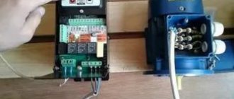
When connecting an asynchronous frequency converter to a single-phase current network, the motor terminals must be connected in a “triangle”. This connection scheme involves connecting the end and beginning of adjacent windings. The supply voltage will be 220 V. The output current must be kept within no more than half of its rated value.
If the frequency generator is connected to a three-phase network, then the motor terminals are connected in a star. With this connection scheme, the ends of the three phases of the windings are connected to one point. The voltage from the network takes the value 380V.
The order of connecting the general electrical circuit will be as follows:
- differential circuit breaker, the current of which coincides with the rated current of the motor;
- frequency converter;
- electric motor
When working with a three-phase network, the circuit breaker must be equipped with a common lever for all three phases. In this case, the overload of one of the phases will be eliminated by turning off the entire power supply. The permissible tripping current must be calculated based on the motor current in one phase.
When installing the converter in a single-phase network, the permissible current of the circuit breaker must exceed three times the value of the phase current.
The converter is connected to the electric motor using a magnetic starter. The magnetic starter is selected based on the mains voltage and rated current.
Before installing the control panel, its lever must be in the “Off” position. When the lever is turned on, a prerequisite is the appearance of a signal on the light indicator. The RUN key starts the frequency generator. And the control panel handle controls the change in the speed of the engine rotor.
You should carefully study the frequency value on the frequency converter, since some models indicate the rotor speed of the electric motor, while others indicate the frequency of the converter current.
Setting up a frequency converter for an electric motor begins with carefully studying the instructions, as it indicates the sequence of these operations.
In order to set up a frequency converter for an electric motor, it is necessary to select the correct type of wires and the correct size of their cross-section.
Before setting up the frequency converter, it is necessary to correctly locate and connect the input and output terminals. The input terminals are marked with the letter L indicating the phase numbering. The output terminals are designated in Latin letters - U, V, W.
Since the factory-made converter has quite a lot of parameters, it is partially configured at the factory. The remaining parameters are configured manually. Main stages of setting up a frequency converter:
- power supply to the frequency converter;
- selection of a specific operating mode;
- setting equipment performance values.