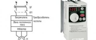
A frequency converter
Based on the method of connecting power to the input terminals, single-phase and three-phase frequency converters are distinguished. In this case, single-phase frequency converters are powered by a phase voltage of 220 V, three-phase by a linear voltage of 380 V. However, the output of the inverter usually produces a three-phase voltage with a phase shift of 120°, the value of which is limited by the supply voltage at the input.
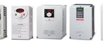
Single-phase and three-phase converters SIEMENS Micromaster 420
In the context of single-phase motors, frequency converters can be roughly divided into three groups:
- Converters specifically designed for single-phase motors.
- Converters with the optional ability to connect single-phase motors, it is necessary to use the appropriate settings and connection diagram.
- Converters without the ability to connect a single-phase motor.
We will look at frequency drivers from the second group.
Note!
Do not confuse converters with single-phase input power with frequency converters that have a single-phase output. Combinations are possible when a converter with a single-phase power supply has 3 phases with a voltage of 220 V at the output, or when an inverter with a three-phase power supply supplies a voltage of 220 or 380 V to a single-phase motor.
How to connect a single-phase motor to a frequency converter?
In addition to the common 3-phase asynchronous motors, single-phase motors are offered on the market. Most often they are pumps and fans. The most popular units in industry and in everyday life. And then the question arises? How to control them and regulate speed. There are a great many ways. But the most effective is when a frequency converter is connected for a single-phase motor.
From this article you will learn:
Single-phase asynchronous motor Motor connection methods Connecting a frequency converter and a single-phase motor
Hi all! Gridin Semyon is with you, and in this post we will talk to you about the nuances of controlling single-phase asynchronous motors. Which control method is better? Let's look at this question - frequency control of the engine in more detail.
Single phase asynchronous motor
Such motors are most widely used in everyday life and small businesses. They are necessary where there is no three-phase network. Their power is limited only by the network frequency. The devices themselves are low-power, ranging from 500 Watt to 2 kiloWatt.
The operating principle of a single-phase motor is to displace the windings in space relative to each other. The key point is the phase shift in the windings by 120 degrees. Our main “phase shifter” is a capacitor. As a rule, it is connected in series in the stator winding circuit.
The design of the motors may vary. So, not everyone can connect a frequency converter; you need to pay attention first of all to the winding connection diagram. A two-phase motor with a working and starting winding will definitely not be able to start; the operating principle is completely different. We'll come back to this later...
Motor connection methods
Now let's look at several connection methods:
- capacitor method;
- frequency method;
- phase control using a triac;
Which method is best? You know, it all depends on the problem that needs to be solved... And so on the taste and color, you know...
If you are not very familiar with the frequency converter, you can read the article “What you don’t know about the frequency converter?”
Capacitor connection method
Low-cost connection of three-phase motors to a single-phase network. We simply connect a capacitor in series in the winding circuit and turn the device from three-phase to single-phase. Here's the diagram:
Sp is a starting capacitor, and Cp is a working capacitor. In this case, I will not describe how to select a container. The Internet is full of information on this matter.
Phase control using a triac
This is one of the oldest methods of management. Two motor windings are connected in parallel, one of them with a capacitor. We connect a triac regulator to the winding points. Their relevance, in my opinion, has not yet disappeared. Best used for light loads (fans, pumps).
Important! Keep in mind that sim. the blocks are mainly designed for resistive loads. Since the motor is an inductive load, we therefore divide the active current by approximately 10. If the active load current is 50, then the inductive current will be 5.
At the output of the device, a mains frequency voltage of 50 Hz is generated and the root mean square number is adjusted. Thus, we change the open time of the triac during the voltage cycle. The only drawback: the torque on the shaft decreases relative to the decrease in voltage. Here's an example from Autonics SPK1:
Inputs for speed control are universal. You can connect a 1 kOhm potentiometer, a sensor with a current signal of 4-20 mA, and a voltage of 0-5 V here.
Frequency method
There is no point in talking about the popularity of the frequency converter. Since this device has long been known to everyone. The frequency method is the main one in our 21st century. The speed is controlled using PWM modulation. A rather complex device that requires a separate article. In terms of input voltage, there are both 380 V and 220 V. But what is the output?
There are ready-made options on the market for both single-phase and three-phase electric motors. You just need to choose a circuit solution.
But, there are cases when an inverter with a single-phase output is not affordable. Or you have a three-phase inverter on your shelf. Let's look at the option of connecting a motor to a frequency converter.
Connection features
As mentioned above, not every frequency converter can work with a single-phase motor, since when it is connected, the third (unconnected) phase will actually be open, which will cause an error. Therefore, it is necessary to carefully read the documentation for the inverter - the manufacturer must clearly indicate that it is possible to connect and operate a single-phase load.
Since a single-phase motor contains a capacitor, when changing the operating frequency it will not be possible to provide the required phase shift, and the motor will overheat at lower frequencies (less than 30 Hz). This should be taken into account when choosing the operating frequency range and the drive cooling method.
When a single-phase motor is connected, operational reverse via the control panel or inverter settings is not possible. You can change the direction of rotation by changing the wiring diagram of the windings inside the motor.
Single phase asynchronous motor
Such motors are most widely used in everyday life and small businesses. They are necessary where there is no three-phase network. Their power is limited only by the network frequency. The devices themselves are low-power, ranging from 500 Watt to 2 kiloWatt.
The operating principle of a single-phase motor is to displace the windings in space relative to each other. The key point is the phase shift in the windings by 120 degrees. Our main “phase shifter” is a capacitor. As a rule, it is connected in series in the stator winding circuit.
The design of the motors may vary. So, not everyone can connect a frequency converter; you need to pay attention first of all to the winding connection diagram. A two-phase motor with a working and starting winding will definitely not be able to start; the operating principle is completely different. We will return to this later.
Setting up the frequency converter
When setting up the frequency generator, you need to pay attention to the following points:
- If possible, limit the acceleration and deceleration times in order to reduce heating of the drive and the motor. The same applies to the number of on/off cycles per unit of time.
- Select scalar frequency control mode.
- Disable phase loss monitoring at the inverter output.
- Before the first start-up, be sure to carry out automatic configuration (adaptation) according to the instructions.
Here you need to pay attention to one important point. A single-phase motor has lower efficiency than a three-phase motor with the same parameters. This should be taken into account when choosing a drive/motor pair. To increase efficiency and reduce heating, you can experimentally set points on the voltage-frequency graph. Alternatively, you can disconnect the starting capacitor, and connect the leads from the starting and working windings to the output of the three-phase converter. Next, carry out the settings as indicated above.
Converting a single-phase motor into a three-phase one
Often a single-phase asynchronous motor turns out to be a three-phase motor. Its conversion to one phase is usually associated with power supply restrictions, which in some locations can only be single-phase.
Before connecting a single-phase motor to the inverter, you can check whether it can operate on three phases. To do this, you need to open the boron, determine the type of engine and its original circuit. Most often it turns out that the drive has a three-phase power supply with a linear voltage of 220 V and is assembled according to the “Triangle” circuit, while a phase-shifting capacitor is used to ensure its operation from one phase. Therefore, it is enough to exclude the capacitor from the circuit and start the engine according to a conventional three-phase circuit.
Other useful materials:
5 steps to connect an unknown motor The benefits of vector motor control Configuring the inverter for multi-motor operation
Features of operating motors with frequency converters
As mentioned above, using a frequency converter for an electric motor, we reduce power losses by reducing the reactive component of the current. In addition, there are some points you need to know:
- When operating at reduced speed, the engine may overheat. This occurs by reducing the speed of natural airflow. Overheating is especially noticeable at speeds close to nominal. To reduce the temperature in this case, it is advisable to use additional airflow.
- When operating a standard electric motor (at 50 Hz) at increased rotation speeds, it is worth considering the condition of the bearings. Due to the stronger vibration that occurs, they fail faster. To level out this phenomenon, vibration damping pads can be used. In addition, the frequency must be chosen so that resonance does not occur. And keep in mind: at higher speeds the electric motor fan will make more noise.
It is necessary to take into account the specifics of the work - When the shaft rotation speed decreases, for normal operation it is necessary to proportionally reduce the load. An asynchronous motor provides maximum torque only at rated speed. Therefore, as the frequency decreases, it falls.
- For long-term operation at reduced speeds, electric motors with a reduced rated frequency are used - from 750 rpm to 1500 rpm. The second option is engines with increased power.
- If you choose a frequency converter for a submersible pump, you need to make a choice not only by power, but also by current. Motors for this category of pumps have a significantly higher rated current. With a large cable length from the inverter to the pump, the voltage can drop significantly, which leads to a decrease in the rotation speed of the electric motor shaft. To make the drop less significant, use a cable with an oversized conductor cross-section.
A frequency converter for an electric motor expands the possibilities of its use. This is important, but it is equally important to choose it correctly, taking into account all the features of the job. This guarantees long-term operation of both devices.