The Stirling engine, once famous, was forgotten for a long time due to the widespread use of another engine (internal combustion). But today we hear more and more about him. Maybe he has a chance to become more popular and find his place in a new modification in the modern world?
The Stirling engine is a heat engine that was invented in the early nineteenth century. The author, as is clear, was a certain Stirling named Robert, a priest from Scotland. The device is an external combustion engine, where the body moves in a closed container, constantly changing its temperature.
Due to the spread of another type of motor, it was almost forgotten. Nevertheless, thanks to its advantages, today the Stirling engine (many amateurs build it at home with their own hands) is making a comeback again.
The main difference from an internal combustion engine is that the heat energy comes from outside, and is not generated in the engine itself, as in an internal combustion engine.
You can imagine a closed air volume enclosed in a housing with a membrane, that is, a piston. When the housing heats up, the air expands and does work, thus bending the piston. Then cooling occurs and it bends again. This is the cycle of operation of the mechanism.
It is no wonder that many people make their own thermoacoustic Stirling engine at home. This requires the bare minimum of tools and materials, which can be found in everyone’s home. Let's look at two different ways to easily create one.
To make a Stirling engine with your own hands, you will need the following materials:
This is all. The rest is a matter of simple technique.
A firebox and two cylinders for the base are prepared from tin, of which the Stirling engine, made with your own hands, will consist. The dimensions are selected independently, taking into account the purposes for which this device is intended. Let's assume that the motor is being made for demonstration. Then the development of the master cylinder will be from twenty to twenty-five centimeters, no more. The remaining parts must adapt to it.
At the top of the cylinder, two protrusions and holes with a diameter of four to five millimeters are made to move the piston. The elements will act as bearings for the location of the crank device.
Next, they make the working fluid of the motor (it will become ordinary water). Tin circles are soldered to the cylinder, which is rolled into a pipe. Holes are made in them and brass tubes from twenty-five to thirty-five centimeters in length and with a diameter of four to five millimeters are inserted. At the end, they check how sealed the chamber has become by filling it with water.
Next comes the turn of the displacer. For manufacturing, a wooden blank is taken. The machine is used to ensure that it takes the shape of a regular cylinder. The displacer should be slightly smaller than the diameter of the cylinder. The optimal height is selected after the Stirling engine is made with your own hands. Therefore, at this stage, the length should include some margin.
The spoke is turned into a cylinder rod. A hole is made in the center of the wooden container that fits the rod, and it is inserted. In the upper part of the rod it is necessary to provide space for the connecting rod device.
Then they take copper tubes four and a half centimeters long and two and a half centimeters in diameter. A circle of tin is soldered to the cylinder. A hole is made on the sides of the walls to connect the container with the cylinder.
The piston is also adjusted on a lathe to the diameter of the large cylinder from the inside. The rod is connected at the top in a hinged manner.
The assembly is completed and the mechanism is adjusted. To do this, the piston is inserted into a larger cylinder and connected to another smaller cylinder.
A crank mechanism is built on a large cylinder. Fix the engine part using a soldering iron. The main parts are fixed on a wooden base.
The cylinder is filled with water and a candle is placed under the bottom. A Stirling engine, made by hand from start to finish, is tested for performance.
The engine can be made in another way. To do this you will need the following materials:
Foam rubber is very often used to make a simple, low-power Stirling engine at home with your own hands. A displacer for the motor is prepared from it. Cut out a foam circle. The diameter should be slightly smaller than that of a tin can, and the height should be slightly more than half.
A hole is made in the center of the cover for the future connecting rod. To ensure that it runs smoothly, the paper clip is rolled into a spiral and soldered to the lid.
The foam circle is pierced in the middle with a thin wire and a screw and secured on top with a washer. Then the piece of paper clip is connected by soldering.
The displacer is pushed into the hole in the lid and connected to the can by soldering to seal it. A small loop is made on the paperclip, and another, larger hole is made in the lid.
The tin sheet is rolled into a cylinder and soldered, and then attached to the can so that there are no cracks left at all.
The paperclip is turned into a crankshaft. The spacing should be exactly ninety degrees. The knee above the cylinder is made slightly larger than the other.
The remaining paper clips are turned into shaft stands. The membrane is made as follows: the cylinder is wrapped in polyethylene film, pressed and secured with thread.
The connecting rod is made from a paper clip, which is inserted into a piece of rubber, and the finished part is attached to the membrane. The length of the connecting rod is made such that at the lower shaft point the membrane is drawn into the cylinder, and at the highest point it is extended. The second part of the connecting rod is made in the same way.
One is then glued to the membrane and the other to the displacer.
The legs for the jar can also be made from paper clips and soldered. For the crank, a CD is used.
Now the whole mechanism is ready. All that remains is to place and light a candle under it, and then give a push through the flywheel.
This is a low-temperature Stirling engine (built with my own hands). Of course, on an industrial scale such devices are manufactured in a completely different way. However, the principle remains the same: the air volume is heated and then cooled. And this is constantly repeated.
Finally, look at these drawings of the Stirling engine (you can make it yourself without any special skills). Maybe you've already got the idea and want to do something similar?
If you're bored and don't know what to do to amuse yourself, you can try to create an electronic motor with your own hands
. You will be surprised to think that this is almost impossible to do at home.
Today “So Simple!”
brings to your attention a simple scheme, following which it will not be difficult to do this at all!
Anyone can easily make such a design, because all the tools necessary for such an engine can be found in any home. And such an experiment
will take very little time. Forget what you were told in physics lessons: perpetual motion does exist!
How to make a simple motor with your own hands
Manufacturing
- Take the wire and wrap it around the battery. It will be enough to make 10-15 skeins.
- Carefully remove the battery. You should end up with a rotor like this. Fix the ends of the wire to the edges of the coil, as shown in the photo below, for this you can tie the wire in a knot.
- You should end up with something like this (for contrast in the photo, one free end of the wire was rubbed with sandpaper, but the other was not).
- For the next step you will need a paper clip and a simple pencil.
- Using a pencil, bend the paperclip like this and attach it to the battery as shown in the photo.
- Similarly, attach a second paper clip to the other side of the battery and connect everything into a single structure using adhesive tape.
- Place a magnet on the top of the battery; it should “stick” to the battery. The rotor should spin quickly; if this does not happen, try pushing it a little with your finger.
That's all, yours original inventionready. By the way, be careful: you cannot leave the rotor stationary for a long time, the battery and coil will get very hot!
Surprise all your friends - show them how easy it is to create a motor with your own hands from scrap materials!
This is a real creative laboratory! A team of true like-minded people, each an expert in their field, united by a common goal: to help people. We create materials that are truly worth sharing, and our beloved readers serve as a source of inexhaustible inspiration for us!
Does it really work? Is there current?
How much wire is needed (cm)
How can you increase the speed of rotation of the wire?
Can I use any wire? I used thin copper, but it didn’t work. doesn't work, what should I do?!
A perpetual motion machine has nothing to do with it. The Ampere force works. Engine
will stop when the battery runs out.
And you can use your fingers
I can't bend the paperclip. Show me how please. I'm 12 children
along the way, the short circuit current moves the rotor!
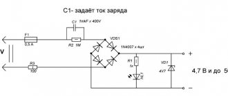
In this article I will tell you how to make a steam engine with your own hands. The engine will be small, single-piston with a spool valve. The power is quite enough to rotate the rotor of a small generator and use this engine as an autonomous source of electricity while hiking.
How to make an internal combustion engine for models with your own hands?
Translated by alexlevchenko92 for mozgochiny.ru
I bring to the attention of brainiacs an article on how to make a jet engine with your own hands .
Attention ! Building your own jet engine can be dangerous. We strongly recommend that you take all necessary precautions when working with crafts , and also exercise extreme caution when working with tools.
The homemade product contains extreme amounts of potential and kinetic energy (explosive fuel and moving parts) that can cause serious injury during gas turbine engine operation. Always use caution and discretion when working on engines and machinery and wear appropriate eye and hearing protection.
Cylinder and spool tube.
Cut 3 pieces from the antenna:
The first piece is 38 mm long and 8 mm in diameter (the cylinder itself).
The second piece is 30 mm long and 4 mm in diameter.
The third is 6 mm long and 4 mm in diameter.
Let's take tube No. 2 and make a hole in it with a diameter of 4 mm in the middle. Take tube No. 3 and glue it perpendicular to tube No. 2, after the superglue has dried, cover everything with cold welding (for example POXIPOL).
We attach a round iron washer with a hole in the middle to piece No. 3 (the diameter is slightly larger than tube No. 1), and after drying, we strengthen it with cold welding.
How to make a piston with connecting rod
Take a bolt (1) with a diameter of 7 mm and clamp it in a vice. We begin to wind copper wire (2) around it for about 6 turns. We coat each turn with superglue. We cut off the excess ends of the bolt.
We coat the wire with epoxy. After drying, we adjust the piston with sandpaper under the cylinder so that it moves freely there without letting air through.
From a sheet of aluminum we make a strip 4 mm long and 19 mm long. Give it the shape of the letter P (3).
We drill holes (4) 2 mm in diameter at both ends so that a piece of the knitting needle can be inserted. The sides of the U-shaped part should be 7x5x7 mm. We glue it to the piston with the 5 mm side.
The connecting rod (5) is made from a bicycle spoke. To both ends of the knitting needle we glue two small pieces of tubes (6) from the antenna with a diameter and length of 3 mm. The distance between the centers of the connecting rod is 50 mm. Next, we insert the connecting rod at one end into the U-shaped part and hinge it with a knitting needle.
The triangle connecting rod is made in a similar way, only there will be a piece of knitting needle on one side and a tube on the other. Connecting rod length 75 mm.
We cut out a triangle from a sheet of metal and drill 3 holes in it.
Spool. The length of the spool piston is 3.5 mm and it should move freely along the spool tube. The length of the rod depends on the size of your flywheel.
The piston rod crank should be 8mm and the spool crank should be 4mm.
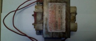
The steam boiler will be an olive jar with a sealed lid. I also soldered a nut so that water could be poured through it and tightened tightly with the bolt. I also soldered the tube to the lid.
Cosmetic modification of the engine. The tank now has its own wooden platform and saucer for dry fuel tablets. All parts are painted in beautiful colors. By the way, it is best to use a homemade alcohol burner
or
Primus
Testing the final version of a homemade steam engine
Since petroleum products are constantly rising in price (after all, oil tends to run out), the desire to save on fuel is quite understandable, and the mini-engine
could be a good solution.
How to make a hydrogen engine with your own hands
Creating a hydrogen generator is an effective way to significantly reduce fuel costs. The task is to supply a special gas (Brown system) into the combustion chamber. Below are simple step-by-step instructions.
Electrolyte assembly
Use 8 stainless steel electrolytic plates (16x20cm) stacked on top of each other. They should already have a hole at the top. Drill another hole 1 cm thick. Place PVC spacers (3 mm thick) between them. The steel plates must not touch each other. Use a screw connection to secure the structure.
Preparing a plastic container
Prepare the container. Insert two long screws inside the cover and seal the gaps with sealant. Attach a wire to each screw by wrapping it around it and leave it outside the container. Make another hole in the lid and insert a rubber hose there, immersing it in water. The other end of the tube should open into the plastic housing of the car's air intake.
You will need to drill a hole in the housing to insert the tube. For a stronger connection, use PVC fittings on both ends. Pour distilled water to fill half the volume. Add half a teaspoon of salt or a full teaspoon of baking soda and mix well.
Place the stainless steel electrolyte into the container, making sure it is well submerged. Any gaps inside the container should be filled with sealant to prevent gas leakage. Bubbles instantly form inside the container and gas begins to be produced.
Connecting to a power source
Connect the terminals of the container screws to the positive and negative terminals of the DC power supply using clamps. If the wires don't make a convincing connection, use wing nuts instead.
You can connect it directly to the battery, the negative contact is connected to the same terminal of the battery, and the positive contact is connected to the ignition relay of the fuse box. This is necessary so that the generator turns on only when the car is also turned on.
It will not be possible to make a full-fledged hydrogen engine for a car with your own hands, since the technology is quite complex.
You need to be logged in to leave a comment.
How economical is a mini internal combustion engine?
As you know, internal combustion engines are divided into gasoline and diesel, and both the first and second are undergoing significant changes today. The reason for the modernization of both the mechanisms themselves and the fuel is the significantly deteriorated environment, the state of which is also affected by the exhaust of equipment operating on liquid fuel. So, for example, eco-gasoline appeared, diluted with alcohol in a ratio of 8:2 to 2:8, that is, such fuel can contain from 20 to 80 percent alcohol. But this is where the modernization ended. There is practically no trend towards a reduction in the volume of gasoline engines. The smallest samples are installed in aircraft models, larger ones are used on lawn mowers, outboard motors, snowmobiles, scooters and other similar equipment.
.
As for, today a lot has actually been done to make this engine truly microscopic. Currently, the Toyota
The smallest minicars
Corolla II, Corsa and Tercel
1N
and
1NT
diesel engines with a volume of only 1.5 liters. One problem is that the service life of such mechanisms is extremely low, and the reason for this is the very rapid depletion of the service life of the cylinder-piston group. There are also very tiny diesel internal combustion engines, with a volume of only 0.21 liters. They are installed on compact motorcycles and construction machinery, but you can’t expect much power; the maximum they produce is 3.25 hp. However, the fuel consumption of such models is low, as evidenced by the volume of the fuel tank - 2.5 liters.
How efficient is the smallest internal combustion engine?
A conventional internal combustion engine, which operates using a reciprocating piston, loses performance as its displacement decreases. The whole point is a significant loss of efficiency when converting this very movement of the CPG into rotational, so necessary for the wheels. However, even before the Second World War, self-taught mechanic Felix Heinrich Wankel created the first working example of a rotary piston internal combustion engine, in which all components only rotate. It is logical that this design, which is very reminiscent of an electric motor, reduces the number of parts by 40% compared to standard engines.
Despite the fact that to this day all the problems of this mechanism have not been solved, its service life, efficiency and environmental friendliness meet established international standards. Productivity exceeds all conceivable limits. Rotary piston internal combustion engine with a displacement of 1.3 liters allows you to develop a power of 220 horsepower
.
Installing a turbocharger increases this figure to 350 hp, which is very significant. Well, the smallest internal combustion engine from the Wankel series, known under the brand OSMG 1400
, has a volume of only 0.005 liters, but produces a power of 1.27 hp. with a dead weight of 335 grams.
The main advantage of rotary piston engines is the absence of noise accompanying the operation of mechanisms, due to the low mass of operating components and precise shaft balance.
How to make a simple internal combustion engine?
The design of internal combustion engines is studied at school by high school students. Therefore, even a teenager can make a simple internal combustion engine with his own hands. To make it you need to take:
- Wire.
- Sheet of cardboard.
- Glue.
- Motor.
- Several gears.
- 9V battery.
- First, cut out a circle from cardboard that will act as a crankshaft.
- Next, you need to cut a 15x8 cm rectangle out of cardboard to make a connecting rod, fold it in half and then another 90˚. Holes are made at its ends.
- Next, a piston with holes for the piston pins is made from a cardboard sheet.
- The size of the piston pins must match the size of the bore in the piston.
- The piston is secured with a pin on the connecting rod, and it must be attached to the crankshaft with a wire.
- In accordance with the size of the piston, you should roll a cylinder out of cardboard, and in accordance with the size of the crankshaft, a box for the crankshaft itself.
The smallest diesel engine as an energy source
If we talk about full-fledged ones, then today the brainchild of engineer Jesus Wilder has the smallest dimensions. This is a 12-cylinder V-type engine, fully consistent with the Ferrar
i and
Lamborghini
. However, in reality, the mechanism is a useless trinket, since it does not run on liquid fuel, but on compressed air, and with a working volume of 12 cubic centimeters it has very low efficiency.
Another thing is the smallest diesel engine developed by British scientists. True, it does not require diesel fuel as fuel, but a special mixture of methanol and hydrogen that spontaneously combusts with increasing pressure. With the clock movement of the piston in the combustion chamber, the volume of which does not exceed one cubic millimeter, a flash occurs, driving the mechanism into action. Interestingly, microscopic dimensions were achieved by installing flat parts; in particular, the same pistons are ultra-thin plates. Already today, in an internal combustion engine with dimensions of 5x15x3 millimeters, a tiny shaft rotates at a speed of 50,000 rpm, as a result of which it produces a power of about 11.2 watts.
Currently, scientists are faced with a number of problems that need to be solved before releasing mini-diesel engines into mass production. In particular, these are colossal heat losses due to the extremely thin walls of the combustion chamber and the fragility of materials when exposed to high temperatures. However, when the tiny internal combustion engines finally roll off the production line, just a few grams of fuel will be enough to make a mechanism with an efficiency of 10% work 20 times longer and more efficiently than batteries of the same size.
Very simple internal combustion engine
The main task is to try to offer an internal combustion engine design that is as simple as possible from all points of view.
Main criteria: · There is no know-how in the engine that would be unknown or even that would not be used somewhere · The number of individual parts should be minimal · The parts themselves are as simple as possible · There are no parts that are very different in complexity from others (with the exception of KShM- we accept it as a classic) Based on these criteria, we set the general appearance: 1. As the most efficient, we select a four-stroke internal combustion engine 2. Number of cylinders 1 or 2 Figure 1 shows the main details of the proposed internal combustion engine. The KShM is a classic one, it is not shown in the picture. The plate (pos. 1) is the basis that provides rigidity between two separate cylinders (pos. 4, 5) and three main bearing housings (pos. 8-9). The cylinders are attached to the plate with studs with clamping strips through a collar, or screwed into threaded mounting holes.
Figure 2: the main bearing mounting bolts (item 10) are pressed into the holes of the plate, secured from turning by a “flat” on the bolt head and a “dead end” on the plate. Then the centering bushings (item 12) are pressed into the holes of the plate. And the upper main bearing housings (pos. 8) are pressed onto them. The crankshaft is laid and the lower main bearing caps are installed (pos. 9), securing them with nuts (Fig. 1, pos. 11). Pistons with connecting rods are installed in the cylinders and connecting rod bearings and caps are mounted . The heads are screwed into the cylinders, orienting them with gas channels using adjusting rings (Fig. 3, item 1). The increased length of the front part of the plate (Fig. 1, size B) is necessary for mounting the oil pump drive gear on the crankshaft. The oil pump itself is mounted on a bracket fixed to the front main bearing housing (not shown in the figure) and the oil system is mounted - a set of steel tubes. Next, the front and rear covers of the internal combustion engine (Fig. 1, pos. 2-3) with seals are mounted. The ICE pan is covered from the bottom (Fig. 1, item 13) ICE mechanisms 1 KShM classic – Kval-Shatun-Pistons. 2 timing belt number of valves one. The world's first internal combustion engine had 1 bottom exhaust valve and an automatic intake valve located in the combustion chamber. The following timing scheme is proposed: with one main valve (closes the gas channel of the cylinder) and an atmospheric valve (controls the flow of gases in front of the main valve). Figure 3: 1 Head 2 Cylinders 3 Main valve 4 Armature 5,6 lower and upper solenoid 7 Atmospheric valve body 8 Atmospheric valve flap 9 Atmospheric valve 10 Removable cooling jacket 11 Adjusting ring
An electromagnetic main valve control circuit is proposed to control the atmospheric damper damper, and an electromagnetic drive is also proposed. You can also use a “classic” mechanical drive with a camshaft, pushers, etc., but this will complicate the design. The diagram contains 2 unusual solutions that cast doubt on its functionality: A) One main and common atmospheric valve for 2 cylinders. C) Electromagnetic valve drive Let's try to theoretically substantiate the operability of this circuit: A. Let's consider the mutual operation of the main and atmospheric valves (Fig. 4).
From Fig. 3 and fig. 4 follows: 1) switching of valves occurs 1 time per 1 revolution of the K-shaft, the requirement for the speed of closing and opening is not very strict 2) the piston should not “catch up” with the open main valve 3) since the main valve is 1, its diameter can be made sufficiently large, increasing the seat-valve cross-section 4) the main valve is washed alternately by hot and cold gases. Which reduces its thermal stress, improves fuel evaporation, although it somewhat reduces the density of the fresh charge 5) it is possible to make the gas channel of the main valve in the head minimally short, reducing the transfer of heat from exhaust gases to the body of the head 6) the requirement for the tightness of the atmospheric valve flap is not very high and insignificant the flow of gas through the gaps will not greatly affect the operation of the internal combustion engine. B. Solenoid valve actuator. The main thing is to ensure the speed of the valves and the tightness of the main one. Speed can be achieved due to: 1) minimal weight of moving parts 2) The absence of “powerful” springs, eliminating their resonance. Although it is possible and advisable to add a “soft” spring to the system that works to open the main valve. 3) Creation of a powerful magnetic force 4) Tightness: generally not achieved by pressing force. And the precision of fitting the mating surfaces. Effort is needed for speed. When grinding the valve, it should already be sealed even under its own weight (kerosene test), i.e. a powerful magnetic closing force is needed to operate quickly and hold the valve at the beginning of the compression stroke. As the pressure in the cylinder increases, the voltage from the magnet coil can be removed altogether, and the valve will be held in place by the high pressure in the cylinder.
Having such a timing design, where the common valve is open during the exhaust-intake strokes, another method of purging the cylinder using gas-dynamic processes in the intake and exhaust tract suggests itself (Fig. 6):
1) inlet pipe, 2) main valve channel, 3) receiver, 4) exhaust pipe, 5) muffler. The peculiarity is that there are no mechanical valves, which makes the system as simple as possible. But it requires complex calculations. To ensure the following processes: 1) since the intake system is connected to each other through the main valve channel directly. During the exhaust stroke, the flow of exhaust gases must completely go into the receiver and exhaust pipe without entering the intake pipe. To do this, the outlet of the intake pipe must be directed in the direction of the flow of exhaust gases in order to achieve the effect of ejection 2) the exhaust tract must be calculated so that while the piston is near TDC, a wave of exhaust gases leaves the receiver, creating a vacuum in it that would fill it with fresh air from the intake pipe, the volume of air must be sufficient to further fill the cylinder, and the exhaust gases would minimally enter the cylinder. Power system The power system can be diesel or gasoline. On gasoline - injection - injection through a nozzle in front of the valve. Fuel must be injected at the very first moment of descent, after switching the atmospheric valve choke to supply fresh charge, so that fuel does not enter the exhaust system. Another method of supplying fuel is proposed - through the hole in the valve seat directly into the “seat-valve” section (Fig. 5)
System elements: 1) El. magnetic valve, 2) shut-off needle with core, 3) spring, 4) air fitting, 5) valve coil, 6) fuel fitting A) Fuel nozzle B) emulsion chamber, C) annular channel in the seat, C) air nozzle, D ) fuel emulsion supply holes The system is, as it were, a hybrid; from the injector there is an electromagnetic valve that supplies fuel in a dosed manner for each cycle at the very beginning of the intake stroke. From the carburetor there is an emulsion chamber B, from where the emulsion through the annular channel B and the supply hole D due to the vacuum on the intake stroke is sucked into the cylinder, and at the very beginning of the intake. Next, the chamber and channels are simply purged with air from the air nozzle, carrying the remaining fuel vapor into the cylinder. During the “exhaust” stroke, exhaust gases, having a slight pressure, can enter the channels and the mixing chamber and then into the air fitting, but their quantity is not significant and should not affect the operation of the system. Feature: the solenoid valve is not an injector, where fuel is supplied under fairly high pressure from an electric pump. Here there is a large diameter nozzle and fuel is supplied under low pressure, which can be obtained from the upper location of the fuel tank and, possibly, creating excess pressure (gas pressure) in the tank itself. The system is also well suited for supplying liquefied gas using gas cylinder equipment.
Almost everything in our lives depends on electricity, but there are certain technologies that allow you to get rid of local wired energy. We propose to consider how to make a magnetic motor with your own hands, its operating principle, circuit and design.
DIY Forum: Gasoline ICE for DIY models - DIY Forum
Ball valves, very simple. The balls can be pulled out of the bearing, but not a very small one. To do this, you need to wrap it in a rag (so that the balls do not fly apart), place it on a piece of iron and hit it on top with a hammer or sledgehammer. inlet valve - just lets air in one direction. You need to carefully tap the ball on the seat - tap it with a hammer when it lies in the seat. It is better to make the intake valve with a pressure adjustment, at first I did it without it, but then I had to redo it. Here is the diagram of the intake valve, I drew it myself, I am not an artist, but I think it will be clear. You need to find something softer for the spring on the intake valve; after assembling the engine, you need to make minimal pressure using a bolt; the exhaust valve is pressed a little harder by the spring; there is no need to make an adjusting screw there. and here is a diagram of the distributor for the exhaust valve. For ignition, it’s better to find a ready-made ignition coil, don’t care why, and connect it according to the classical scheme. I have an ignition coil, but there are no condensers to connect it, and I made the ignition from an old transformer. It’s certainly not the best, but works. You are looking for a transformer that must give a good spark, when connected to the secondary 12 - 18 volts. you need to paraffin it thoroughly, otherwise it will sew through. A button breaker will not work here - there will be no spark. you need to cut a strip of tin, bend it as in the photo and screw it under the crank so that the crank shaft makes a tin contact. You need to bend the strip with your fingers so that the current opens, does not close, but OPEN in the middle of the piston stroke. By the way, you need to put a copper wire ring on the crank shaft to improve contact. One wire to the shaft, the other to the strip. but the transformer also matters, for example mine gives a spark that can ignite fuel well at 18 volts. You can make a homemade spark plug, but when I made it, I didn’t know how, I just glued a motorcycle spark plug into the engine. I hope you know how a Lenoir engine works, if anyone doesn’t know, everything is described here. I don’t want to advertise this site, I just made it myself, and there I found how to make ball valves and everything else. Here is my exhaust valve, you can clearly see the valve ball and the spark plug must be soldered or glued to the cylinder with epoxy glue. I have valves made of aluminum, they cannot be soldered, and I don’t have a soldering iron. That’s why I glued them together. We seal the cracks with cotton wool impregnated with epoxy; all joints must be covered with a cloth impregnated with epoxy for strength. but then I also made it so that the smoke would not come out from the valve, but through the exhaust pipe) gam_romka_er, make it bigger, such a small Lenoir will not work IMHO. There must be at least 5 volume cubes and the valve must be in the cylinder head, do not confuse it with a regular one two-stroke. damn I wrote
Types and principles of operation
There is the concept of perpetual motion machines of the first order and the second. First order
- these are devices that produce energy on their own, from the air,
the second type
is engines that need to receive energy, it can be wind, sun rays, water, etc., and they convert it into electricity.
According to the first law of thermodynamics, both of these theories are impossible, but many scientists do not agree with this statement, who began the development of second-order perpetual motion machines operating on the energy of a magnetic field. Photo - Dudyshev's magnetic engine
A huge number of scientists have worked on the development of a “perpetual motion machine” at all times, the greatest contribution to the development of the theory of a magnetic engine was made by Nikola Tesla, Nikolai Lazarev, Vasily Shkondin, the variants of Lorenz, Howard Johnson, Minato and Perendeva are also well known .
Photo – Magnetic Lorentz motor
Each of them has its own technology, but they are all based on a magnetic field that is formed around the source. It is worth mentioning that engines do not exist in principle, because... magnets lose their abilities after approximately 300-400 years.
The simplest is considered to be a homemade anti- gravity magnetic Lorentz engine
. It works by using two differently charged disks that are connected to a power source. The disks are half placed in a hemispherical magnetic screen, the field of which begins to gently rotate them. Such a superconductor very easily pushes the MP out of itself.
The simplest asynchronous electromagnetic Tesla motor
based on the principle of a rotating magnetic field, and is capable of producing electricity from its energy.
An insulated metal plate is placed as high above ground level as possible. Another metal plate is placed in the ground. A wire is passed through a metal plate on one side of the capacitor and the next conductor goes from the base of the plate to the other side of the capacitor. The opposite pole of the capacitor, being connected to ground, is used as a reservoir for storing negative energy charges. Photo – Tesla Magnetic Motor
Lazarev Rotary Ring
so far it is considered the only working VD2, in addition, it is easy to reproduce, you can assemble it with your own hands at home, using available tools.
The photo shows a diagram of a simple Lazarev ring motor: Photo - Lazarev’s Koltsar
The diagram shows that the container is divided into two parts by a special porous partition; Lazarev himself used a ceramic disk for this. A tube is installed in this disk, and the container is filled with liquid. For the experiment, you can even pour plain water, but it is advisable to use a volatile solution, for example, gasoline.
The work is carried out as follows: using a partition, the solution enters the lower part of the container, and due to pressure, it moves upward through the tube. So far this is only perpetual motion, independent of external factors. In order to build a perpetual motion machine, you need to place a wheel under the dripping liquid. Based on this technology, the simplest self-rotating magnetic electric motor of constant motion was created; the patent was registered to one Russian company. You need to install a wheel with blades under the dropper, and place magnets directly on them. Due to the resulting magnetic field, the wheel will begin to rotate faster, water will be pumped faster and a constant magnetic field will be formed.
Shkondin linear motor
brought about a kind of revolution in progress.
This device is very simple in design, but at the same time incredibly powerful and productive. Its motor is called a wheel-in-wheel and is mainly used in the modern transportation industry. According to reviews, a motorcycle with a Shkodin engine can travel 100 kilometers on a couple of liters of gasoline. The magnetic system works for complete repulsion. In the wheel-in-wheel system, there are paired coils, inside of which another coil is connected in series, they form a double pair, which has different magnetic fields, due to which they move in different directions and a control valve. An autonomous motor can be installed on a car; no one will be surprised by a fuel-free motorcycle with a magnetic motor; devices with such a coil are often used for a bicycle or wheelchair. You can buy a ready-made device on the Internet for 15,000 rubles (made in China), the V-Gate starter is especially popular. Photo – Shkondin engine
Alternative Perendeva engine
is a device that works solely thanks to magnets.
Two circles are used - static and dynamic, with magnets placed on each of them in equal sequence. Due to the self-repelling free force, the inner circle rotates endlessly. This system has been widely used in providing independent energy in households and industries. Photo - Perendeva Engine
All of the above inventions are in the development stage, modern scientists continue to improve them and look for the ideal option for developing a second-order perpetual motion machine.
In addition to the listed devices, the Alekseenko vortex engine, Bauman, Dudyshev and Stirling apparatuses are also popular among modern researchers.
How to make a hydrogen engine with your own hands
Creating a hydrogen generator is an effective way to significantly reduce fuel costs. The task is to supply a special gas (Brown system) into the combustion chamber. Below are simple step-by-step instructions.
Electrolyte assembly
Use 8 stainless steel electrolytic plates (16x20cm) stacked on top of each other. They should already have a hole at the top. Drill another hole 1 cm thick. Place PVC spacers (3 mm thick) between them. The steel plates must not touch each other. Use a screw connection to secure the structure.
Preparing a plastic container
Prepare the container. Insert two long screws inside the cover and seal the gaps with sealant. Attach a wire to each screw by wrapping it around it and leave it outside the container. Make another hole in the lid and insert a rubber hose there, immersing it in water. The other end of the tube should open into the plastic housing of the car's air intake.
You will need to drill a hole in the housing to insert the tube. For a stronger connection, use PVC fittings on both ends. Pour distilled water to fill half the volume. Add half a teaspoon of salt or a full teaspoon of baking soda and mix well.
Place the stainless steel electrolyte into the container, making sure it is well submerged. Any gaps inside the container should be filled with sealant to prevent gas leakage. Bubbles instantly form inside the container and gas begins to be produced.
Connecting to a power source
Connect the terminals of the container screws to the positive and negative terminals of the DC power supply using clamps. If the wires don't make a convincing connection, use wing nuts instead.
You can connect it directly to the battery, the negative contact is connected to the same terminal of the battery, and the positive contact is connected to the ignition relay of the fuse box. This is necessary so that the generator turns on only when the car is also turned on.
It will not be possible to make a full-fledged hydrogen engine for a car with your own hands, since the technology is quite complex.
You need to be logged in to leave a comment.
How to assemble an engine yourself
Homemade products are in great demand on any electricians forum, so let's look at how you can assemble a magnetic motor-generator at home. The device that we propose to construct consists of 3 interconnected shafts, they are fastened in such a way that the shaft in the center is turned directly to the two side ones. Attached to the middle of the central shaft is a disk of lucite, four inches in diameter and half an inch thick. The outer shafts also feature two-inch diameter discs. There are small magnets on them, eight on the large disk and four on the small ones.
Photo – Magnetic motor on suspension
The axis on which the individual magnets are located is located in a plane parallel to the shafts. They are installed in such a way that the ends pass near the wheels with a flash per minute. If these wheels are moved by hand, the ends of the magnetic axis will be synchronized. To speed things up, it is recommended to install an aluminum block into the base of the system so that its end slightly touches the magnetic parts. After such manipulations, the structure should begin to rotate at a speed of half a revolution per second.
The drives are installed in a special way, with the help of which the shafts rotate similarly to each other. Naturally, if you influence the system with a third-party object, for example, a finger, it will stop. This perpetual magnetic engine was invented by Bauman, but he was unable to obtain a patent because... At that time, the device was classified as a non-patentable VD.
Chernyaev and Emelyanchikov did a lot to develop a modern version of such an engine.
Photo - How a magnet works
What are the advantages and disadvantages of actually working magnetic motors?
Advantages:
- Full autonomy, fuel economy, the ability to use available means to organize the engine in any desired place;
- A powerful device using neodymium magnets is capable of providing energy to a living space up to 10 VKt and above;
- The gravitational engine is capable of working until it is completely worn out and even at the last stage of work it can produce the maximum amount of energy.
Flaws:
- The magnetic field can negatively affect human health, especially the space (jet) engine is susceptible to this factor;
- Despite the positive results of the experiments, most models are not able to work under normal conditions;
- Even after purchasing a ready-made motor, it can be very difficult to connect it;
- If you decide to buy a magnetic pulse or piston motor, then be prepared for the fact that its price will be greatly inflated.
The operation of a magnetic motor is the pure truth and it is real, the main thing is to correctly calculate the power of the magnets.