Purpose
These devices perform several functions at once:
- Quick shutdown of equipment and electrical appliances in single-phase networks in cases where voltage parameters exceed established limits. In the same way, the protection is triggered when the neutral conductor breaks.
- Protection of equipment and other connected loads at a given facility from the influence of pulse-type voltage surges resulting from the operation of nearby sources of such pulses. In this case, all devices and electronic equipment are reliably protected from destruction and possible fire.
Protective devices fully monitor the voltage state and prevent possible triggering causes. After shutting down in emergency mode, the UZM protection device turns on automatically when the mains voltage returns to normal. This switching occurs after a certain delay time, configurable by the user.
Such protective equipment can be used for any configuration of electrical networks - TN-C, TN-S, TN-CS, TT. At the same time, its use does not at all cancel traditional means of protection - automatic machines, RCDs and others.
In addition to protection, UZM-50Ts reduces inrush currents when connecting capacitive loads. In this case, the relay contacts close at zero mains voltage when it passes through the neutral conductor.
Protection device UZM-50TS UHL4
PURPOSE
The multifunctional protection device UZM-50TS (hereinafter referred to as the Device) is intended for:
- shutdown of equipment when the voltage value in single-phase networks goes beyond the established parameters or the neutral wire breaks;
- protecting equipment (in an apartment, office, etc.) from the destructive effects of pulsed voltage surges caused by the operation of nearby motors, starters (etc.) connected to the same network, thereby preventing equipment failure and possible fire;
OPERATING PRINCIPLE OF THE DEVICE
When power is applied, the device begins monitoring the mains voltage. If the mains voltage is between the values of the upper Umax and lower Umin thresholds specified in the settings, the countdown of the automatic reclosure (AR) time begins. In this case, the indicator displays the time in seconds until the load (equipment) is connected to the network. During the AR time countdown, the “ton” indication periodically appears on the display. If before the end of the AR time countdown the network voltage does not go beyond the set response thresholds, then at the end of the countdown the load will be connected to the network.
Then the device enters the mode of displaying the current value of the network voltage, and the indicator will display the “U” sign for 1s, then the device will display the current value of the network voltage. To switch to the load current indication mode, you must press the “-” button once, the “A” sign will appear on the indicator for 1s, then the device will display the current current value. To switch to the power consumption indication mode, you must press the “-” button once, the indicator will display the “P” sign for 1s, then the device will display the current power value. When in the voltage, current or power display mode, the symbol of the selected display mode (U, A or P) is displayed on the display at intervals of 10 seconds and 1 second.
The “+” button is used to turn the load on or off without a time delay. When you press the “+” button, the on/off state of the relay contact will change. If the relay is turned off manually, then resetting and reapplying power will not automatically turn on the load to the network. When the relay is turned off, the indicator appears at intervals of 10 seconds. “OFF” is displayed for 1 second, and the current input voltage value is displayed.
During operation, the Device continuously monitors the mains voltage and the power consumed by the load.
When the mains voltage goes beyond the set response thresholds (accidents), the device counts the response delay. If the duration of the voltage fault remains longer than the corresponding response delay, the load is disconnected from the network. The display shows “U.Er” for 1 second, the device automatically switches to the mode of displaying the measured voltage. After normalizing the voltage, the device connects the load after counting down the automatic reclosure time. If, during the AR time countdown, the network voltage again goes beyond the specified response thresholds, the AR time countdown will be reset.
When the network voltage is below 80V, the indicator displays
If during operation of the device the power consumed by the load exceeds the set response threshold, the device will switch to the “P” power display mode and begin counting the load disconnection time. During the countdown of the load disconnection time, the “normal/emergency” LED lights up red and flashes green twice. If the permissible power is exceeded until the end of the countdown, the device will disconnect the load from the network and begin counting the on-time equal to the off-time value (“t. P”, set in the device settings). During the countdown, the “normal/emergency” LED lights up green and flashes red twice, while on the indicator for 1 second. "ton" is displayed. If, after turning on the relay, the excess power consumption remains, the countdown of time “t. P", with the switching time "t. P" in the next cycle increases by the same time "t. P".
In order to reduce inrush currents when switching on capacitive loads, the built-in power relay is switched on at zero mains voltage (the mains voltage crosses zero, “zero sync”™ technology).
During operation, the Device writes into non-volatile memory the values of the minimum and maximum network voltage, the maximum power consumed by the load, as well as the number of load outages for each type of accident.
| Mains voltage (U) | U<85V | 100Vmin | Umax | U>300V |
| Load shedding time | 0.1 sec | 10 sec | 0.1 sec | Less than 0.02 sec |
IMPORTANT! When the device is triggered, only the phase wire is broken. The neutral wire N passes through for ease of installation and is not switched. It is allowed to connect terminal N only on one side (For example, when connecting three UZMs to a three-phase network, you can combine the neutral terminals on one side with a PSM jumper).
KEY FEATURES
- Can be used in networks of any configuration; TN-C, TN-S, TN-CS, TT;
- Does not replace other protection devices (circuit breakers, SPDs, RCDs, etc.);
- In case of short-term (less than 0.5 s) dips in the mains voltage, it does not disconnect the load;
- Rated switching current 63A
- Two-threshold overvoltage protection (delay): >240-290V/(0.1s), >300V ±15%/(20ms)
- Two-threshold undervoltage protection (delayed response): <100-210V/(10s) and <80V±10%/(100ms)
- Built-in varistor protection against surges in mains voltage
- Adjustable reclose delay (RE) 2-999 seconds
- Remains operational in a wide range of supply voltages 0…440V
- Synchronous relay control - relay contacts are closed when the mains voltage crosses zero, “zero sync”™ technology
- Measuring network parameters: voltage, current (current measurement range - from 0.6A to 65A) , power
- PROTECTING settings with a PIN code (upper and lower thresholds for voltage, AR time, power)
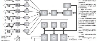
DEVICE DESIGN
The device is produced in a unified plastic case and is a voltage control relay with a powerful electromagnetic relay at the output and varistor protection. The device is installed on a 35 mm wide DIN mounting rail (GOST R IEC 60715-2003) with front connection of the power wires of the protected electrical circuits. Tunnel design terminals provide reliable fastening of wires with a total cross-section of conductors up to 33 mm.
Structurally, the UZMs are made on printed circuit boards with electronic components installed on them, an indicator, a relay, a current shunt, and power buses. Thanks to this design, high mechanical rigidity (solidity) of the product and high reliability are achieved.
In the latest release of UZM, larger size terminals with a window of 9.0x8.2 mm are installed. and a locking screw M6. To avoid installation errors, the device terminals are equipped with protective “flags”
CONNECTION DIAGRAM
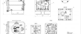
DIMENSIONS
Additional information about the parameters and operating modes of the device can be found in the product data sheet (the “files” tab).
Principle of operation
After voltage is applied to the protective device, there is a time delay of 5 seconds and the indicators are off. In the case of a normal voltage state, the indicator begins to blink green during this period, and the display shows the remaining time until the device turns on. At the end of the time delay, the load is connected to the supply voltage, and the green LED stops blinking and lights up continuously.
If during the period of delay and countdown the voltage goes beyond the standard response limits, the countdown will stop and be reset. The indicator will show red instead of green, and the display will show the current voltage value.
In normal operating condition, UZM-50Ts continuously monitors the voltage. If high-voltage pulses suddenly appear in the network, a varistor comes into action, shunting them to a safe value. If the supply voltage goes beyond the established thresholds, the countdown of the time delay before the device operates begins. For the upper limit it is 0.2 s, and for the lower limit it is 10 s. If during this time the voltage does not return to normal, the load will be disconnected from the network.
Single-phase voltage control relays, part 4 - Meander UZM-51M (2019)
Continuation of the series of reviews about single-phase voltage control relays, started here: Part 0 - UZM-51M Part 1 - PH-260t Part 2 - UZM-50Ts Part 3 - UZM-51M (2018) “Now I love you, now I praise you I" (Korney Chukovsky) No, Meander hasn’t bribed me yet, it’s just that the device turned out to be quite normal. This relay was sent by a colleague to be tested with passion, which is what I’ll actually do. As it turned out, in this voltage control relay the manufacturer has eliminated many critical shortcomings of previous versions. Currently, it is this version of the UZM-51M that is being produced and sold in some places. Attention!
When purchasing, pay attention that the LEDs are at the bottom, the terminals have curtains and the busbars are bare copper. Manufacturer Passport
Everything is sold in the same unified box with a window.
The package includes the device itself and a passport in Russian. The body of the device has been changed again, now the LEDs have crawled down. Unfortunately, the date on the case is not indicated (why would that be?), there is a sticker on the box -02.19- i.e. February 2021 The body is glossy gray, still does not support combustion, the inscriptions are painted
The terminals are clearly different, more about them below
It can be disassembled just as easily as the previous modification - with self-tapping screws. One under the latch, the second under the seal.
Immediately striking is the absence of insulating cardboard, a copper zero bus of a larger cross-section hard-soldered onto the board, and reinforced power connection terminals with M6 screws. Protective curtains have finally appeared on the terminals, preventing the wire from being connected past the terminal. This is a really useful device for inexperienced electricians and ordinary consumers. The design of the device itself is quite technological, it’s a pleasure to assemble and disassemble, I liked it
The printed circuit board was also changed
The relay was installed new at 80A, with a shunt and powerful busbars.
A raccoon hid under the varistor
The varistors themselves could be additionally heat-shrinked.
Storage capacitor.
Controller PIC12F683
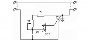
Electrical circuit diagram
The power relay was supplied with a new MP26 with reinforced busbars and a built-in 0.3 mOhm current-measuring shunt, which is not used in any way in this device. The zero bus is apparently not made of high-purity electrical copper, so its surface is quite heavily oxidized. It practically does not affect the work, but it does not look very aesthetically pleasing. Meander
, coat your tires to protect them from oxidation.
The actual cross-section of this tire is 8x1.4mm=11mm^2, which is more than enough. The power relay buses are clearly made of copper of a higher class and have a clean, shiny surface. + Resistor R1 was installed in a normal output version of sufficient power + Transistors VT3 and VT4 were supplied with normal, proven BSS123 + R20 was removed, now the yellow output voltage control LED is powered through R13 and R16. The solution is quite acceptable. — For some reason, they reduced the brightness of the green and red LEDs (HL1 - R21 and HL2 - R24). Agree that it is a little strange to supply a current of only 0.035 mA to the LED through a 100 kOhm resistor. Most likely, the resistor values were mixed up at production. It would be better to leave the brightness as it was because now the LEDs are really hard to see when installing the shield externally. I changed these resistors to 30kOhm and 10kOhm as they were in previous versions, now the brightness is normal. Square wave
, return the brightness back to how it was - The 0.1 µF shunt capacitor was not traditionally installed at the DA1 input, I added it myself. All changes circled
There are no more changes.
The UZM-51M withstood a short-term voltage of 480V normally. Long-term supply of 440V did not reveal any problems. The measuring stand has undergone some changes, now the increased voltage is supplied in a sharp jump and it is possible to more accurately track the response time of the protection. Voltage divider at the oscilloscope input 1:15 (full scale 600V), sweep 5ms/div, relay setting 175/265, supplied control voltage 220V/400V
As a result, the software part was also improved, now the shutdown time has become noticeably faster - from 15ms to 35ms, depending on the moment the increased voltage is applied. This speed is quite sufficient for reliable protection of any equipment. It is clearly seen that only the positive half-wave of the mains voltage is analyzed, which triggers the protection. This is why there is such a large variation in the relay response time. The relay always turns off at the decline of the half-wave, which is the correct solution. The speed of response to low mains voltage is not so critical, so there was no point in checking it with an oscilloscope.
Conclusion: I personally liked this device and I can recommend it for purchase. All detected minor defects are not critical and do not reduce the level of reliability and safety of the device. As usual, it didn’t turn out perfect, we’re waiting for the next versions...
To be continued, RBUZ is next...
Characteristics
The nominal value of the supply voltage for UZM-50Ts is 230 volts, with a frequency of 50 Hz. The main indicators are measured in the ranges: voltage - from 30 to 440 V, current - from 0.6 to 65 amperes, power - from 0.18 to 20 kW. The relative measurement error for current is 2%, for voltage – 1%.
When choosing a UZM voltage relay, it is necessary to take into account other important indicators:
- At elevated voltages, the adjustable shutdown frames range from 240 to 295 V.
- The same figures for reduced voltage range from 100 to 190 V.
- Fixed shutdown thresholds: for the upper limit – 300 V, for the lower limit – 80 V.
- Load shutdown in case of excess power consumption is carried out within adjustable limits from 0.5 to 14.5 kW.
- The turn-on or restart delay can be adjusted from 3 to 999 seconds.
The consumption of voltage relays for their own needs is quite insignificant. Electricity consumption is no more than 2.2 Wh, and power consumption does not exceed 2.2 W. The rated load current is 63 A, when connecting copper conductors with a cross-sectional area of at least 16 mm2. The rated power of the connected load is 15.7 kW.
The overload current and the time of its impact, at which contact welding does not occur, are 3000/10 A/ms. The UZM-50TS UHL4 device can operate normally in the temperature range from -25 to +55 degrees. The device is capable of withstanding short circuit currents without any damage - up to 6 thousand amperes. The marking AC230V means the rated current.
UZM-50TS can be placed in any position and operate around the clock. If all operating conditions and rules are observed, the service life of the UZM reaches 10 years.
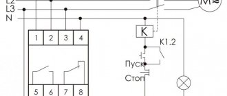
Connection diagram UZM-50TS
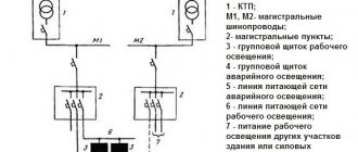
There are different options for connecting the Meander UZM-50TS device. In the first case (Fig. 1) at the input, the phase and neutral conductors are connected to the upper contacts. There are also contacts at the bottom of the device, from which phase and zero go to the load. This circuit is used most often, and when triggered, a phase is opened. Another scheme (Fig. 2) is rarely used and is distinguished by the inclusion of a neutral wire.
If the UZM-50Ts protection device is installed in a three-phase electrical network, the connection diagrams discussed above are used separately for each phase. That is, for normal operation, three protective devices will be required.