Relay functionality
The phase control relay (PKF) is designed to protect industrial and household electrical equipment from abnormal operating conditions of the power supply network. The device controls such parameters as:
- presence of all 3 power phases;
- shift angle between phases;
- voltage symmetry;
- the voltage value in each phase separately.
A common area of application of the device is the protection of asynchronous electric motors. They are unable to operate on 2 phases. In this mode, engines quickly fail. Using a monitoring relay, a circuit is implemented that turns off the motor when one of the phases is missing.
Note! In its task, the RKF resembles a three-phase voltage control relay. Both devices monitor the voltage in the network. But the phase control relay has a wider range of settings and capabilities.
Design and principle of operation
Most devices of this type are designed for mounting in electrical cabinets of protected equipment. The housing is equipped with a latch for mounting on a DIN rail. There are controls on the front for setting response limits.
The operating principle of the device is based on continuous monitoring of the network status. If the voltage or angle between phases goes beyond a critical level, the protective device will generate a shutdown signal and put the equipment out of operation. The shutdown occurs with a time delay. Its value is also adjustable.
Connection procedure
A preliminary familiarization with the features of its design will help you understand how to connect the relay. This process will be significantly facilitated by understanding the operating principle, as well as the ability to configure the device immediately before startup.
Structural elements
The relay housing is designed for installation on a DIN rail or on a previously prepared flat surface. The external connector allows you to connect it to the electrical network using standard clamps, to which copper conductors with a cross-section of up to 2.5 mm2 are supplied. On the front panel there are adjustment controls, as well as a control lamp indicating that the device is turned on.
The operating circuit includes indicators of an emergency situation and the connected load, as well as mode switches, asymmetry and time delay regulators. To connect the device, three terminals are used, designated L1, L2 and L3. Like circuit breakers, they do not provide for the connection of a neutral conductor (this is not true for all relay models).
On the device body there is another contact group of 6 terminals, used to connect to control circuits. For this purpose, a harness containing the appropriate number of wires is provided in the wiring of power equipment. One of the contact groups controls the coil circuit of the magnetic starter, and the second controls the switching of equipment connected to the line.
Setting items
The instructions for connecting and setting up assume the presence of various circuit solutions for the device itself. In the simplest models, no more than one or two regulators are displayed on the front panel. This is how they differ from samples with advanced settings. In models with a large number of control elements (they are called multifunctional), a separate block of microswitches is provided. It is located on a printed circuit board located directly under the device body or in a special hidden niche.
The desired relay configuration is obtained by sequentially adjusting each of the available adjusting elements. With their help - by rotating the control knobs while simultaneously pressing the corresponding microswitch - the required protection parameters are set. Their installation step or the sensitivity of the device for most samples is 0.5 Volts.
Types of RKF
Different RKF models have different technical characteristics. Therefore, each of these devices belongs to one type or another.
According to the settings options, relays are divided into 2 categories:
- Adjustable. It is possible to set the required response setting for voltage and time (EL-11, EL-12, EL-13, EL-15).
- Unregulated. Only factory settings are supported. An example of such a device is E-511.
Relay EL-13E
Main technical parameters
Protective devices are used in a wide range of equipment. Therefore, their parameters can differ markedly depending on operating conditions. Of the most important technical characteristics of the phase control relay, the following are noted:
- operating voltage;
- response adjustment limits;
- response delay time;
- Operating temperature range;
- storage conditions.
Supply voltage
This parameter is selected depending on the supply voltage of the protected equipment. If it operates from 380 V, then a relay with a similar voltage value is selected. In addition, RKFs for 110 and 220 V linear voltage are common.
Important! Line voltage is the potential between phase wires. Usually it is 380 V. The phase voltage is between the phase wire and the neutral. Usually this is 220 V, like in an apartment socket.
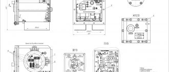
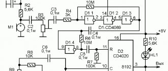
Phase control unit for maximum line voltage 250V
RKF settings limits
Different phase control relays have different adjustment limits. If the equipment is designed to work with precise parameters of the supply voltage, then you can choose a relay with a narrow control range of 0.9-1.1 Un, which is suitable, for example, for electric motors.
If the accuracy of the supply voltage is not important, then a relay with a range of 0.7-1.3 Un is suitable. Such protective devices are suitable for three-phase heating devices and heating elements.
On/off delay
Many industrial consumers of electricity have a nonlinear starting characteristic. At the moment the engine or heating element is turned on, the starting current is tens of times higher than the rated current. Accordingly, the voltage drops during startup.
To prevent RKF from turning off the network when the voltage drops, an operation delay has been added to its operating algorithm. When the engine starts, the voltage drops below the permissible level, but the relay does not turn off the power for some time. This parameter can be adjusted using the control on the front panel of the device.
Working temperature
Extreme heat or cold has a detrimental effect on the electronic circuit of the RKF. An abnormal temperature value can lead to a drift in the characteristics of the internal radio components of the device, which will provoke its false alarms and shutdowns. Also, sudden cooling can cause condensation of water vapor inside the device, which will damage it. Therefore, it is important to observe the temperature regime of the RKF.
For example, devices of the EL-11E, EL-12E and EL-13E series are capable of operating at temperatures from –40 to +80°C. Therefore, they can be used in conditions of not too frosty winters.
Storage requirements
Every electronic device has both operating and storage conditions. Usually they are similar. Any phase control relay must be stored in its original packaging. If possible, avoid exposing the device to humid environments or extreme temperatures. During storage, vibration and unnecessary transportation of the relay should be avoided.
Setting up work
Now how can we check that we have connected everything correctly? You need to act step by step:
- Without the participation of the RKF (we close its output contacts for now), we start the compressor and make sure that its motor rotates in the right direction. If the engine spins in the wrong direction, immediately turn off the power and... call a familiar electrician)))
- We make sure that with this connection (correct phase sequence), the phase control relay responds to it correctly. That is, there are no errors, and the output relay is turned on (the yellow indicator is on). If the alternation is broken (the indicators blink alternately), you need to swap any two wires at input terminals 1, 3, 6.
- We connect the output terminals to the control circuit, turn on the compressor again, check its operation, and get a profit.
Review of popular phase control relays
There are dozens of models from domestic and foreign manufacturers on the market. Each of them has its own features and technical characteristics. When choosing an RKF, you need to take into account who produces it and for what purposes.
Zamel CKM 01
Three-phase phase rotation control relay with DIN rail mounting. Has a compact size. The width is standard for 1 module and is 17.5 mm. More detailed characteristics are shown in the table.
| Supply voltage | Single-phase 220 or two-phase 380 V |
| Maximum permissible voltage for contacts | 250 V |
| Internal relay power limit | 2.5 kVA |
| Output contacts | 1NO and 1NC |
| Maximum switching current | 10 A |
| Own consumption | 34 mA |
| Class of housing protection against dust and moisture | IP 20 |
| dimensions | 9x17.5x6.6 cm |
Zamel CKM 01 device for DIN rail mounting
RNPP 311
Relay from domestic. Installed in a panel on a DIN rail. It has a minimum of adjustment controls on the front panel, which makes it suitable for service even by untrained personnel.
| Rated supply voltage | 380 V |
| Mains frequency | 45-55 Hz |
| Own current consumption | No more than 35 mA |
| Voltage regulation range | 1.05-1.25Umax (for Umin similar values) |
| Fixed shutdown delay | 12 sec |
| Starter coil voltage | 110-380 V |
| Critical supply voltage values | 80-500 V |
| Working temperature | –25 +40°C |
| Climatic performance | UHL4 |
| Number of switching cycles at 5 A load | At least 100 thousand times |
Voltage monitor RNPP-311
ABB 1SVR750488R8300
ABB specializes in high-quality electrical equipment. The quality matches the price. The relay in question costs about 11 thousand.
| Control supply voltage | 450 V |
| Operating frequency | 50-60 Hz |
| On/off delay | 0.1-30 sec |
| Number of switching (changeover) contacts | 2 |
| dimensions | 85.6x45x104.8 mm |
OMRON K8AB
A compact device that has a slightly different purpose than the usual RKF. OMRON K8AB does not control voltage, but current. Therefore, an additional current transformer is required for its operation. The manufacturer positions the device as an ideal tool for monitoring current in industrial heaters and electric motors.
| Supply voltage (depending on modification) | 24 AC/DC current or 100-115 V or 200-230 V |
| Controlled current | 2 mA– 200 A |
| Number of controlled phases | 1 |
| Maximum output relay current | 6 A |
| Actuation hysteresis | 5-50 % |
| Model of the current transformer required for operation of the relay | K8AC-CT200L |
Important! Hysteresis, in simple terms, is a switching delay. It allows you to turn the relay on and off at different current values. This is necessary to prevent excessive switching and mechanical wear of the contacts. For example, the relay turns off at 5 A and turns on at 4. Or the temperature controller turns off the heater when the room is 24°C and turns on when 18°C.
Carlo Gavazzi DPC01
Multifunctional three-phase RKF with an expanded list of adjustments. Relays from this manufacturer are found in industrial compressor equipment. The front panel has standard voltage and delay regulators. As well as indicator LEDs, which facilitates human interaction with the device.
| Supply voltage | 24 V DC current or 230 alternating |
| Output current limit | 8 A |
| Adjusting the response delay | From 0.1 to 30 sec |
| Trigger voltage adjustment range | 2-22% of nominal value |
| Number of controlled phases | 3 |
| Degree of protection against dust and moisture | IP 20 |
| Installation | DIN rail |
| Limit voltage for output relay contacts | 550 V |
Euroautomatika FiF CKF-318-1
Belarusian phase control relay, which has proven itself as a simple, cheap and reliable solution for protecting electric motors. This RKF is triggered by a critical decrease/excess of voltage and the loss of one or more supply phases. Characteristics in the table.
| Operating voltage | 220/380 V |
| Output relay current limit | 8 A at 250 V |
| Contact type | 2NO and 2NC |
| Alarm indicator color | Red |
| Voltage lower limit range | 150-210 V |
| Upper voltage limit range | 240-280 V |
| Hysteresis | 5 V |
| Power consumption from the network | 1.6 W |
Relay for monitoring presence and phase rotation F&F CKF-318-1
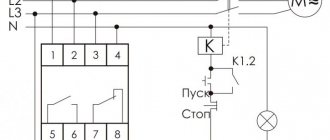
Phase control relay.
In ATS circuits of a three-phase network, the phase control relay provides constant monitoring of the supply voltage of the main input
.
In the event of a decrease or increase in voltage at the main input, a malfunction or a break in any of the phases, the relay switches the consumer to the backup input
, thereby protecting electrical equipment from emergency modes of the electrical network.
The relay also controls the order of phase rotation (phasing), which allows you to determine the correctness of the supply voltage coming to the consumer. If the phase rotation of the power input at home is disrupted, for example, ASV instead of ABC, then the relay will not go into operating mode until the error is eliminated. In addition, these relays operate in conjunction with electrical equipment for which incorrect phase rotation can lead to breakdown or incorrect operation.
The domestic industry produces a sufficient number of different types of relays for three-phase and single-phase networks, but the most widely used relays are the EL series - EL11E
,
EL-12E
,
EL-13E
, which were designed to work in our electrical networks, and where each type of relay in this series has its own area of application.
So relay type EL-11E
designed to monitor voltage levels and is used to protect power supplies, generators, and also as monitoring devices in ATS systems.
EL-12E
serves to control the order of phase rotation and voltage asymmetry (phase imbalance) and is used to protect powerful asynchronous electric motors with a power of up to 100 kW operating in irreversible mode.
EL-13E
controls only voltage asymmetry (phase imbalance) and is used to protect three-phase crane asynchronous electric motors with a power of up to 75 kW operating in reverse mode.
EL series relays are available with different response times - 0,1
;
0.15
;
0.5
seconds, as well as with adjustable delay from
0.1
to
10
seconds, which avoids false alarms in the presence of short-term disturbances in the electrical network.
Almost all phase control relays have the same device: indication of normal and emergency network conditions, measuring and power parts.
Measuring part
, as a rule, has an adjustable setting of the lower and upper voltage thresholds, and an adjustment of the relay response delay.
The power part
is a conventional electromagnetic relay, the contacts of which are used in the control circuits of ATS systems.
Pros and cons of domestic relays
Equipment developers and adjusters periodically have to choose between domestic and foreign automation manufacturers. On the one hand, you want to do everything cheaper, and on the other, more reliable. To make the right choice, you need to consider the pros and cons of each option.
Advantages of Russian control relays:
- Low price. Imported RKFs cost at least 2 times more.
- The device can operate at temperatures below –25°C. Among foreigners, such endurance is less common.
- Russian EL series relays do not require additional 24 V power supply. Most foreign relays require an additional voltage source.
Devices produced by the Electrical Engineering Company Meander
Disadvantages of Russian RKFs:
- High heat dissipation. This indicates unreliability of power contacts or high consumption of auxiliary current.
- Incorrect operation of RKF analog circuits. Sensitivity to external interference.
- Outdated appearance. Although in the last decade there has been a “thaw” in terms of the design of domestic automation.
Circuit design
Within reasonable limits, the RKF connection diagram depends on the developer’s imagination. The standard device has 3 inputs for connecting phases. They are usually located at the top of the device. At the bottom there is a terminal block with 4 pins - NO and NC relay contacts. Some actuator is connected to them. For example, a more powerful relay, contactor or magnetic starter. It is possible to connect the load directly, but you need to take into account the current it consumes.
Relay design elements
Old Soviet relays for monitoring open-circuit and phase rotation were fixed to the mounting location using 2 screws. Modern devices are equipped with DIN rail mounting. This approach simplifies the repair and development of electrical cabinets.
The second design feature of the phase control relay is screw terminal blocks for connecting wires. The vast majority of protection devices are equipped with such contacts.
Adjustable controls
Regulators for setting the relay operating parameters are located on the front panel. This allows you to make changes without removing the device itself from the electrical panel. The regulators are made on the basis of trimming resistors. They do not stick out from the surface of the device. To rotate them, you must use any suitable screwdriver.
Some models of network imbalance protection relays are equipped with buttons and a display. In such devices, nothing needs to be rotated. However, it is somewhat more difficult to understand what is regulated and how. Especially without a user manual.
Electronic control device
Pin assignment markings
In terms of marking and designation of terminals, everything is the same as on any modern devices. The letters on the device body have the following designations:
- L1, L2, L3 - terminals for connecting 3 phases of the controlled network;
- NO/NC — output relay contacts;
- Umax is the maximum voltage threshold at which RKF will turn off the protected equipment;
- Umin - respectively, the minimum shutdown threshold;
- delay - the time after which the relay will operate.
Note! NC/NO (normal closed / normal open) - normally closed/open relay contacts. This marking is used on all modern equipment. The NC contacts are in a closed state and are short-circuited with a multimeter if voltage is not applied to the relay coil. As if it was just lying on the table. NO - opposite contacts. Without voltage they are in an open state.
Bottom line
At any industrial enterprise there are hundreds and thousands of three-phase asynchronous motors. No matter how modern and reliable the motor is, if during operation one of the phases feeding it disappears, it will burn out. The cost of the largest and most powerful engines is comparable to the price of a good car. A control relay costs much less than a motor. But it will definitely save him in the event of a phase failure. This explains the economic feasibility of installing RKF for engine protection.
Voltage quality is important not only for asynchronous machines. When there is a short circuit in the line, the voltage in one of the phases drops to almost zero. This mode of operation is unacceptable. RKF will notice a critical voltage imbalance and turn off the line. Thus, all consumers will be protected from abnormal operating conditions and subsequent losses.
With this in mind, the RKF is far from the least important protective device. It has not lost any relevance since Soviet times. On the contrary, with the development and complexity of equipment, the relay is only becoming more in demand, because it allows you to protect expensive electrical machines from breakdown.
Connection in the compressor. Real example
The compressor control circuit is powered by 24 V AC voltage from a transformer. There is an “Emergency Stop” switch installed in the power circuit, which simply cuts off the power when you press it. I have already written in detail about the purpose and operation of emergency shutdown circuits in the article Why control and emergency circuits are needed in industrial equipment.
The photo shows the contacts of this switch (left, top):
Compressor emergency stop switch, through which power is supplied
What can I say? I connected the relay inputs to the compressor power supply input terminals. And since the compressor power supply is purely three-phase, without a neutral, it was necessary to use grounding instead of a neutral to power the RKF.
Operating torque for installing and connecting the phase control relay:
The process of installing the FiF phase control relay in a working compressor
Done, CKF-318-1 installed:
RKF Euroavtomatika FiF CKF 318-1 installed
As you can see in the photo, I used the zero terminal, since it is not used anyway, as a partition between the contactor and the relay. After all, the contactor heats up during operation and can have a negative impact on the hero of the article.
By the way, did you notice anything unusual in the compressor circuit? An experienced eye will immediately see that there are no circuit breakers in the cabinet. After all, I myself wrote a little higher that engine protection is required to be installed! So, do the Germans not know about this, or did they save a few Euros?
It's simple - the compressor is part of more complex equipment, and is powered through fuses:
Connecting the compressor via fuses as part of other equipment
Although, the protection is so-so, and a 10 A heater would definitely not hurt.