This sensor can be used in an automatic lighting control system to turn on the lights based on its signal if someone is walking or talking in the room, by clapping their hands, or in a security system to respond to noise in a place where there should be no noise , and many other uses can be found for it.
The main feature of the sensor is that its amplification stages are made on logical inverters of the CD4069 microcircuit, switched to analog amplification mode. This sensor is another demonstration of how logic chips can operate in analog mode.
Acoustic sensor circuit
The sensitive element of the sensor is microphone M1. A miniature microphone from a voice recorder is used here; it is electret; unfortunately, its type is not known (there is no marking), but with a high degree of certainty it can be said that almost any standard electret microphone with two terminals and a built-in amplifier can be used here.
Power is supplied to the microphone through the blocking RC chain R1-C1, resistor R2 serves as a load for its built-in amplifier. The signal through capacitor C2 is sent to trimming resistor R3, which can be used to adjust the sensitivity of the sensor as a whole.
Next, the signal goes to the low-frequency amplifier, made on logic elements D1.1-D1.3 of the CD4069 microcircuit. In order for these elements to operate in analog amplification mode, a circuit of three series-connected elements is covered by feedback consisting of resistors R4 and R5. Theoretically, the gain of this amplifier will be equal to R5 divided by R4.
In fact, it will be significantly lower. Another amplifier is made on element D1.4; this element is switched to analog mode by a feedback circuit consisting of resistor R6.
If there is a sufficient volume level, this amplifier goes into limiting mode and chaotic pulses of logical amplitude appear at its output, which are sent through capacitor C5 to pin 11 of counter D2. Circuit C5-R7 converts these pulses into positive ones, and the first of them sets counter D2 to zero.
The initial position of counter D2 is such that there is a logical one at its highest output (pin 3). In this case, the high logical level from pin 3 of D2 goes through a diode to pin 13 of D1.5. And on elements D1.5 and D1.6 there is a multivibrator that generates pulses supplied to the counting input of the counter D2 (to its output 10).
While a logical one passes through pin 13 of D1.5 through VD1, the multivibrator D1.5-1.6 is blocked and does not generate pulses.
If, however, the sound level is sufficient to trigger the sensor, then the amplitude of the pulses from output D1.4 will be sufficient to reset counter D2. At the same time, a logical zero is set at all its outputs, including the senior one. In this case, diode VD1 closes and ceases to influence the input of logic element D1.5.
Multivibrator D1.5-D1.6 starts and generates pulses arriving at input “C” of D2. A logical zero at pin 3 of D2 lights up the indicator LED and serves as a signal that the sensor has triggered.
Rice. 1. Schematic diagram of an acoustic sensor (sound relay) on two microcircuits.
Then the situation can develop in two ways. If the sound stops, then counter D2 will count the pulses generated by the multivibrator D1.5-D1.6, and, after about 15 seconds, a logical one will be set at its pin 3. The LED will go off and diode VD1 will turn off the multivibrator.
If the sound does not stop, or is repeated more often than once every 15 seconds, then counter D2 will be periodically reset to zero by pulses from output D1.4, and will not reach a state with one at pin 3.
Thus, the zero at pin 3 of D2 is present for as long as the sound sounds, occurring at intervals of at least 15 seconds, plus another 15 seconds. For example, if this sensor were to control a lamp by clapping your hands, then after each clap the light would be on for 15 seconds.
The time of 15 seconds is not critical, it can be changed as you like, to do this you need to change the frequency of the pulses generated by the multivibrator on D1.5-D1.6 accordingly by selecting resistance R8 or capacitance C6.
Acoustic relay on a triac
The acoustic relay is capable of turning on and off a load with a power of up to 500W using a sound command (voice, clap, whistle). The main switching element is the BTA06-600 triac, which can be replaced with a more powerful one without recalculating the circuit ratings. Thus, the power of the switched load of the acoustic relay can be expanded to 1-2 kW.
Previously, I published a similar circuit in the article “Acoustic switch”, but the advantage of the relay described here is that the circuit is powered from a 220V AC mains voltage. As a result, the device does not require a transformer power supply or switching power supply.
The acoustic relay itself consumes only about 10W.
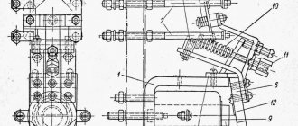
Acoustic relay circuit on a triac
Metal film capacitor C11 for voltage 630V. The remaining non-polar capacitors are ceramic. Zener diode VD2 voltage 12V. The microphone must be an electret type. Transistor VT1 can be replaced with MPSA42 or S9013 (but S9013 has a different pinout).
The circuit is powered by 12V DC. It is organized using a damping capacitor C11, rectifier diodes VD3, VD4, a zener diode VD2 and a pulsation-smoothing electrolytic capacitor C10.
The signal from the microphone is fed to a low-frequency amplifier made on transistor VT1. The amplified and biased signal (by voltage divider R5R6) is supplied to the input of timer U1 (pin 2). When a certain signal level is reached, the timer generates one rectangular pulse, which is sent to the synchronization input (pin 3) of trigger U2. In this case, the trigger is transferred to the opposite state and at its direct output (pin 1), the low level is replaced by a high level or vice versa. The operation of this chain is described in more detail in the article “Acoustic switch”.
A high signal level (approximately +5V) from the direct output of the trigger goes to the U3 microcircuit for controlling the triac VS1, which in turn connects or disconnects the load.
The sensitivity of the acoustic relay is set by trimming resistor R4.
It is necessary to install a radiator on the triac using heat-conducting paste. The surface area of the heat sink must be at least 200 cm2. Without a radiator, the power of the switched load should not exceed 100W.
The power paths through which the load current flows must be made wider and covered with a layer of tin. If VS1 is replaced with a more powerful version, then the traces of the printed circuit board must be tinned with a thick layer of tin, and, if necessary, a copper core must be soldered along them.
Attention! When starting the circuit, as well as during its operation, it is prohibited to touch the elements of the acoustic relay, since the device is not galvanically isolated from the mains voltage. This is necessary to prevent electric shock.
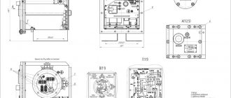
Printed circuit board of an acoustic relay on a triac
Parts and their replacement
The HL1 LED is needed only to demonstrate the operation of the sensor; in a real device it can be excluded from the circuit.
The CD4069 chip can be replaced by any of the “...4069” or the domestic analogue K561LN2. The CD4020 chip can be replaced by any of the “...4020” or the domestic analogue K561IE16.
The supply voltage can be from 5 to 15V, but it must be taken into account that as the supply voltage increases, the amplifying properties of the amplifier stages based on inverters of the CD4069 microcircuit decrease.
Tyulgin Yu. M. RK-2016-04.
Principle of operation
This acoustic switch operates on a special microcontroller that allows you to turn off the light by clapping your hands. Of course, such a control device can be used not only to control a lamp, but also many other electrical devices: fans, air conditioners, transformers.
Photo - cotton model EV-01L
The simplest sound switch consists of an electronic microphone in which a preamplifier is installed. Thanks to this part, any sound that enters the device is amplified several times, due to which even the smallest pops are perceived by the sensitive element. The operation of the amplifier itself is additionally controlled using transistors VT1 and VT2. The circuit is regulated by two resistors R2; rectifying diodes VD1 and VD2 are installed to level the signal.
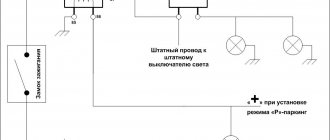
Photo - diagram
When a clap sounds, the signal passes through the microphone and is amplified, after which it is converted into an electrical impulse. This pulse is equalized by rectifying diodes. The sound at which the light turns on is controlled by a resistor, i.e., if the sound of the clap does not exceed a preset value, the light bulb or other device connected to the switch will not turn on. After leveling the signal on the capacitor (indicated C8 in the diagram), the voltage increases, then the transistor switch VT3 opens.
Turning the light off and on is done by alternately discharging and charging the capacitors. After a full cycle of repeated clapping, the resistor and capacitor C10 will be discharged within 4 seconds, and the device will go into the off state.
Acoustic switch device
The microphone amplifier is assembled on two bipolar transistors of the KT 315 series. In order to increase the sensitivity of the microphone, you can use transistors of the KT 368 type or their imported analogues (SS 9018).
The power part of the circuit is a powerful transistor KT 818, which controls the load. If you want to control a large load, you can use a relay with a supply voltage of 3.5 to 15 volts.
When controlling loads with power up to 12 volts, you can remove the relay from the circuit and connect the load instead. If you need to control loads powered by the network, then you definitely need a relay. During the clap, the microphone receives the wave and feeds it to the power amplifier, they take turns amplifying the signal received from the microphone.
The already amplified signal arrives at the base of the switch, its magnitude allows the transistor to operate, and at this moment the junction of the transistor opens and conducts current. It powers the connected load or relay. When there is another clap, the generation is interrupted and the relay is de-energized.
The simplest circuit of an acoustic switch
The simplest effective acoustic switch circuit can be assembled by anyone with the desire and time. Such a switch can be used for various purposes, for example, to turn on and off the lighting in a room using a clap; the same principle of operation and control of any equipment. In general, this acoustic switch is a very useful thing in home use.
This sensor makes it possible to turn on and off power circuits using a clap. Such a device can be used to turn on the light.
It is quite sensitive due to the presence of a double amplifier using low power transistors. It responds well to clap from a distance of five meters from the microphone.