How to control a lamp from several places, and even using regular buttons instead of key switches? In order for this to work, you need to have a pulse (bistable) relay. Some sources call it pulsed, some bistable, so both names are appropriate - choose whichever you like.
Using a circuit consisting of a bistable relay plus any number of buttons (like a bell), you can control the lighting from any number of places. This is needed in long corridors, rooms where it is possible to enter the room from two sides, in bedrooms where the main light can be turned on both at the door and at the bed.
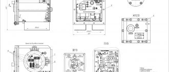
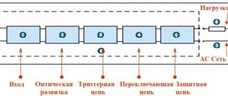
Block diagram of a bistable relay
The operating principle of a pulse relay is shown in the animated figure (look at it carefully):
- The phase potential (L) goes to both the button and the relay.
- When we use the button (S1) to apply potential to the relay, it closes the internal contact of the relay and supplies power to the lamp, even if the button (S1) is released.
- Subsequent application of potential to the relay using the button will turn off the lamp until the button is pressed again.
- Both the lamp and relay must be connected to the neutral (N) wire for everything to function as it should.
DOUBLE RELAY WITH SELF-LOCKING
In electronics, a latching relay is often used, which maintains either of two latched states even after the control signal has been removed. We will now consider the circuit of its equivalent. There are basically two types of electromechanical relays:
- Contact Return Relays - These relays are most widely used where excess power consumption is not a problem. This type of relay returns to its original state after the input signal is lost.
- Latching Relays - These relays are used primarily in automobiles or other specialized equipment.
Most of the relays we use today are monostable relays, which have only one stable state. They distinguish between NO (normally open) and NC (normally closed) contacts. That is, the ordinary electromagnetic relay that we most often use has only one stable state.
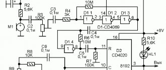
This circuit will show how, using a regular non-locking (non-self-locking) relay, to create a full-fledged two-position self-locking relay, which is powered from an external voltage source. You can use this module in many automation and control projects, such as lighting control and so on.
Here is the circuit diagram of the relay module. Its basis is the NE555 timer chip, which forms a 1-bit memory cell. Such a relay block can be controlled either by a button or by a 5V logic signal through the provided inputs.
In the circuit, connector J1 is needed for the inputs and control logic of the module, and connector J2 is connected to the switched relay contacts. The following is a description of the contacts for the operation of the module:
- VCC - 5V DC (you can take it from the USB port)
- GND - negative ground voltage.
- SET INPUT - voltage to turn on the relay.
- RESET INPUT - voltage to turn off the relay.
Please note: this is not a fully latching relay. As soon as you turn off the power, the relay will return to its original position and until power is supplied again, it will continue to be in a normally open or normally closed state. The classic self-latching relay will remain in the latched position even when the power is turned off. That is, it works and switches state only when power is applied. Then it returns to its original state again.
In addition to buttons, this module can be controlled using signals from any microcontroller. For testing, we connected the relay to a wireless communication module via the Wi-Fi of a smartphone and controlled the switching remotely through a special program.
Thus, this bistable relay can be used not only to control a conventional electromechanical relay, but also to control a solid state relay. And this provides ample capabilities and functions to this device.
Simple connection diagram
The simplest circuit has one button and a bistable relay located with this button. Such a system makes sense only when the relay can be controlled from another source, for example, using a remote control or a central control system (smart home element).
- Mains power 220V is connected to the terminal (L) of the button (S1).
- The electrical potential from terminal (L) is transferred directly to the relay terminal (1) (PB). The potential from this wire will be transferred to the lamp when the relay operates.
- We connect the neutral (N) and protective (PE) wires outside the button (P1). The protective wire (PE) is connected to the PE terminal in the lamp, and the neutral wire is connected to the N terminal of the lamp and to the terminal (A2) of the relay.
- When the button is used to indicate the potential at terminal (A1) of the relay, the relay connects terminals (1) and (2) together with the contact and the lamp turns on. After releasing the button, the contact will remain closed, so the lamp will remain on.
- The change will occur when the button is pressed again and the relay opens the contact, breaking the connection between terminals (1) and (2).
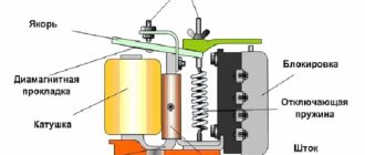
What is a bistable pulse relay
How does a conventional electromagnetic relay work? Applying voltage to the inductor produces a magnetic field that attracts the switch tongue. The tongue is connected to the contacts and performs the task provided for by the relay design - turning on, off, switching. When the voltage is turned off, the magnetic field disappears and the spring returns the tongue and contacts to their original state. Unlike a conventional relay, a bistable relay operates on the trigger principle. It is always in one of two stable states - on or off. When a voltage pulse is applied to the winding, the relay switches to another state. The next impulse returns it to its original state. An electronic bistable pulse relay works on the same principle.
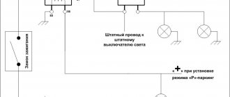
Connection diagram of a pulse relay for lighting control
Relay control from two places
The electric potential from the phase wire (L) is transferred to terminal (2) of the button (S1), both when the button (S1) and (S2) are pressed. Inside in the diagram you can see the coil symbol which controls the relay contact when we apply voltage to terminals (A1) and (A2).
This way we can attach any number of buttons to control the light independently from different places. If you want to add an additional control from another location, simply add another button into the circuit and connect it in parallel to any other button that controls that lamp, or directly to a relay.
Bistable relay with two buttons
Now let's take a bistable relay, which can be installed outside the box, for example, in a home switching device. So here is another connection diagram for you to study.
This is essentially the same as in the previous figure, only the shape of the relay has changed.
Useful: Capacitive soil moisture sensor
What does a pulse relay look like?
Here is the test system. The bell button will be installed in a box and connected to a bistable relay. On the right side of the relay there are 3 independent electrical connectors connecting the phase, neutral and protective wires. The power cord is currently connected to them.
- Control terminals (A1) and (A2).
- Terminals (2) and (1), to which we connect the power cord and the phase wire to the lamp.
- In the central part of the relay there is a black button that can be pressed manually without bell contact buttons connected by wires.
Pulse relay device
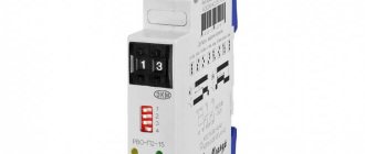
As an example, consider a pulse relay with a staircase machine (timer) BIS-403 produced by the Belarusian company F&F, the appearance of which is shown at the beginning of the article. There is also its brother, model BIS-413 , assembled in a different housing.
The main parameters and connection diagram are shown on the device housings. At first glance, the case is of high quality, but it is assembled without a single bolt; hot glue is used as fasteners. However, what is needed from the device, which must be installed in the installation box, as indicated in the instructions. So, open it, we see:
Electronic pulse relay BIS-403 – view from the parts side 1
The basis of the device is the ST 78522 controller (correct me if I’m wrong), I did not find a datasheet for it. Also - a 5 Volt voltage stabilizer 78L05, a couple of rectifiers, diodes and electrolytes.
Electronic pulse relay BIS-403 – view from the parts 2
The terminal device that controls the flow of current through the load is a conventional relay of the HF118F type. The contacts of this relay determine the power of the switched load. On the relay body it is written “10 A 250 VAC”, but this is hardly worth believing - such contactors will not be able to pass 2.5 kW through themselves.
It is better to believe what is written in the instructions (you can download it at the bottom of the page, there is also a connection diagram) - 2 Amperes of reactive load. It's 400 watts, which is quite possible. And for a load greater than 0.5 kW, I would install an additional contactor or a more powerful relay for reliability.
In addition, for reliability and protection, it is necessary to install a current-matched circuit breaker in series.
Electronic pulse relay - view from the soldering side
Practical relay connection
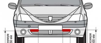
Before starting work, be sure to turn off the voltage in the electrical circuit and use a tester to check the presence of 220 V potential on the wires with which we will work.
Connect the power cable (2) to the phase wire connector.
We will run a two-wire cable between the box and the relay. We will connect the brown wire to the connector so that we can press the external button.
The second wire is blue, it will have potential. Let's connect it to the control contact (A2) of the relay.
The next step is to connect the clamp (A1) to the neutral wire connector and also connect the wires to the lamp. The conductors and neutral protection are connected to the appropriate connectors, and the brown wire (phase) to the terminal (1) of the relay so that it operates by receiving the potential supplied to the terminal (2).
The button connection is classic. Connect the power cord to terminal (L) and to terminal (2) of the wire, with the help of which we will transmit short relay control pulses.
Then we attach another button to the circuit. To do this, we will run a two-wire cable between two boxes.
In the second, we can install a backlit bell button so that we can see changes in the potential on it. The connection method is similar. We connect the wires by color in the same way as in the first button.
Everything is ready - click and check the operation of the test system.