0
2948
28.05.2019
To create automation of many processes, special devices called time relays are produced. The article describes in detail their purpose, technical characteristics, how to use, what types there are, advantages and disadvantages, and how not to make a mistake when choosing products. Also included are diagrams for connecting the device and how to do it yourself.
What it is
A time relay is a device based on the battery principle. It often functions as a switch and breaker. The operating time of this device can be hourly, daily or weekly. Many types of switches are equipped with an electromagnet to mechanically operate the switch. There are also solid-state relays, which have no mechanically moving parts. By using low voltage levels applied to the control terminals, such devices are used to turn a high-power circuit on and off.
When electric current passes through the coil, it generates a magnetic field. The field activates the armature, and subsequent movement of the moving contact (or contacts) creates or breaks (depending on the design) a connection to the fixed contact. If the group of contacts was closed when the device was de-energized, then the movement opens the contacts and breaks the connection, and vice versa if the contacts were open. When the current in the coil is turned off, the armature returns with a force approximately half that of the magnetic force to its natural position. Typically this force is provided by a spring, but gravity is also widely used in industrial motor starters. Most of these devices are manufactured for faster operation. In low voltage conditions it reduces noise, and in high voltage conditions it reduces sparking.
Typically, 12 V, 24 V and 220 V time relays with turn-off delay are produced and produced.
What principle should be implemented in a homemade time relay
The basis of homemade automatic releases with timers is the launch of a configured (selected) shutter speed. Often this is a low-voltage product (5–14 V), less often it is made for direct connection to a regular network (diode options).
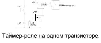
Basics of the simplest assemblies
The timer in this case is a capacitor, the duration of its discharge is the countdown. Charging begins by pressing the switch button. The actuator is an electromechanical relay (looks like a small box), after the capacitor is “emptied”, the current at its contacts disappears and decoupling occurs.
The circuit also includes a tuning (variable, tuning) resistor to adjust the delay, but in general the range is set by the capacitance of the capacitor (you can select different ones experimentally for the required intervals) - it affects the duration of its discharge, respectively, the general pause frame.
Where and how it is used
220V time delay relays are common in the areas of electrical power distribution and generation. The protection they provide to high-voltage lines creates trouble-free operation of substations, as well as other equipment.
Protection control elements are manufactured for connection switching at very high operating voltages (several thousand Volts).
Thanks to the installation of relay protection, it is possible to back up power lines, as well as instantly disconnect damaged or dangerous sections of power networks.
Electromagnetic type devices are widely used in various types of household appliances, such as washing machines, refrigerators, etc.
Today, time relays of this type are widely used in control systems for production and conveyor lines. Such control systems are usually used in industries with high parasitic potentials, at which control of semiconductor systems becomes impossible.
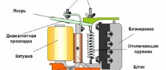
Design Features
- Coil.
- Fixed magnetic circuit.
- Armature (coil or moving part of the magnetic circuit).
- Release spring and block contacts.
- Adjustment screw.
- Traverse.
In the place where the armature and the core come into contact, a non-magnetic gasket is placed. It is needed so that the anchor does not stick directly to the core. If there is no gasket, then the rebound spring will not be able to withstand the holding force of the residual magnetism of the core. In this case, the device will not be able to turn off.
The delay time of a time relay is the time from the moment the pulse is applied to the coil itself until the period of contact activation. Adjustment of the shutter speed is done by changing the thickness of the gasket and tensioning the tension spring using a screw, depending on the type of device. The duration of exposure depends on the thickness of the spring tension and the thickness of the non-magnetic gasket. The lower the voltage and the thinner the gasket, the longer the endurance.
Making a time relay with your own hands
Electrical appliances can be turned on and off according to a planned schedule automatically without user intervention; for this, there are special devices that close contacts at the desired moment, determined by the setting. Some products are initially supplied by manufacturers with a programmable circuit breaker. For devices without it, they purchase such a device, but they also design a time relay with their own hands. Let's analyze several proven methods for assembling an on/off timer.
Specifications
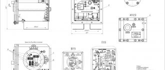
Dimensions of 12 Volt time relay with off delay: 65x36x23 mm.
Dimensions of the device 220 volts with switch-off delay: 68x86x18mm.
- Mains voltage. Limits: upper – from 220 V to 280 V, lower – from 120 V to 210 V.
- Supply voltage ranges from 100 V to 420 V.
- Rated current – 5 A, 16 A, 25 A, 32 A, 40 A, 50 A, 63 A.
- Current consumption – 2.8 mA, 5.8 mA (for the SR 1 model), 10 mA, 76 mA, 86 mA.
- Rated load power – 1 kVA, 3 kVA, 5.5 kVA, 7 A, 8.8 kVA, 11 kVA, 13.9 kVA.
- Load connection delay period (adjustable) from 3 to 600 seconds.
- The load power off time during voltage reduction is from 1 to 0.04 seconds depending on the type of device. During voltage increase - from 0.01 to 0.05 seconds.
- The permissible number of starts (with a connected load) is from 50,000 to 100,000 times.
- For a three-phase design, it is possible to adjust the phase imbalance in the range from 10 V to 80 V.
- Adjustable time for a given skew from 0 to 30 seconds.
Protection Standards:
- IP 20 – protection of the device against penetration of objects with a diameter exceeding 12.5 mm into its body.
- IP 56 – protection against normal and strong water jets.
What are the types?
Electronic types
This is the most common variety. They have a process control function with a delay of a few fractions of seconds. The continuous operation time is several thousand hours. They are small, consume little electricity and have different additional functions depending on the manufacturer.
Electromagnetic retardation devices
They require direct current to operate. During the increase in the main magnetic current, the delay of the device is triggered, so another flux is created in the additional winding, which prevents the main one from increasing.
Pulse or bistable relay
—Pulse relays differ from electronic ones in that when a voltage pulse is applied to them, it turns on, when the next pulse is applied, it turns off. It is used in automation and security systems. When a pulse is given from one polarity, the armature occupies one position, simultaneously closing a pair of contacts. When a pulse of reverse polarity is applied, the armature occupies a diametrically opposite voltage, also closing a pair of contacts.
Pressure switch
—Pressure switch—designed to automate the water supply system. It is responsible for turning the pump on and off automatically when the water pressure changes
With pneumatic retardation
This type has a pneumatic damper. To adjust the time, you need to change the cross-section of the hole. These devices have a large number of contacts that can transition from a normally open to a normally closed state. This type of switch is used where sequential control is needed. Their coils are easily replaced, and the time delay ranges from 0.4 to 180 seconds.
Devices with a clock or anchor mechanism
They work using a spring that is driven under an electromagnet. The anchor mechanism begins to work when the specified time is set on the scale. The 2РВМ device is a classic representative of this variety. Its purpose is to control two electrical circuits (independent) for closing and opening. They are controlled thanks to daily programs, which are installed by installing pins in two special disks.
Motor devices
They are distinguished by a high time delay - from five seconds to three to five hours.
Software relay
It is used for communication of electric motors, automation of local circuits and lighting loads. They differ from other types in that the contacts are made of silver, and from programmable logic controllers in a small number of input/output channels, a small amount of memory and the inability to perform complex mathematical operations.
Shutdown delay relay for 15-30 minutes
Hi all! The circuit of a conventional turn-off delay relay will not surprise anyone; assembling one is not difficult at all. Do you want it loosely, do you want it on a microcircuit, or if you are an advanced solderer, then on a microcontroller with indication on the display and sound….
I also needed a simple turn-off delay relay for 15-30 minutes. And I wanted it to turn on and be able to turn off before the set time with just one button. And as usual, my desire is most easily realized using a microcontroller, which I am not familiar with...
So I want to tell and show you about my version of the implementation of this circuit. The circuit, the board and my thoughts on setting up are in the archive at the link in the description under the video. It all started with the fact that lately I haven’t really wanted to sit in the car on a cold seat in the morning in the winter... Of course, I made the heating element myself, but it’s easier and faster to buy a ready-made one, like this one.
You can connect this wonderful device in several ways: 1-In the screwdriver! There is already a switch on the wire coming from the heater. 2-Through a small connector under the seat, bringing the wires to each seat through a separate 7.5 A fuse under the sill trim and carpet. I settled on the second option. And then I had a question about turning this heating on and off. Here, too, you can use several options: 1-Install a regular small-sized button with a lock, connecting it through a relay with a contact current of at least 20 A.
2-Assemble or use a ready-made turn-off delay relay.
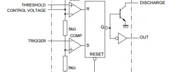
As it turned out later, 30 minutes is enough for the seat to warm up. And then, while driving, the interior warms up and seat heating seems to be unnecessary. This is my opinion and I do not impose it on anyone! Personally, I wanted to have the following functionality for heated seats: 1-Start the car, press the button to turn on the heated seats. While the car engine is warming up, the seat also has time to warm up and sit on it comfortably. After 15-30 minutes (depending on your desire for heating operation time), the heating will automatically turn off. 2-If the fifth point begins to boil before this time, then the heating can be turned off with the same button by pressing it again. The heating also turns off when the ignition is turned off. I took my favorite and affordable NE555 timer as a basis. It works quite predictably and the ability to enable and use it is publicly available on the Internet.
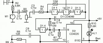
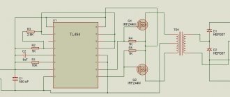
This circuit was taken as the basis for the seat heating delay relay.
Works great, but I wanted to turn it on and off earlier 15-30 minutes with the same button! I had to do a little magic with a soldering iron on this circuit and attach something like a single-vibrator on transistors and a capacitor; the signal for on-off was sent through resistors from the switching contacts of the relay.
Imitation of winter conditions was carried out in an air conditioning unit, like the freezer of a home refrigerator. And after final assembly at the time of publication, this scheme worked for two not very winter Belarusian seasons without complaints or problems. This miracle works something like this: The main power supply is supplied past the ignition switch (for example, from the cigarette lighter), through fuse F1. Since I have two heated seats, I assembled two identical circuits for each seat.
The control part of the circuit is low-current and in my case is powered through the VD3 diode (sort of reverse protection) from the ignition switch. If you want the seat heating to work even when the ignition is off, discharging the battery while you are not in the car, you can connect the anode of the VD3 diode to fuse F1.
When the ignition is turned on, voltage is applied through the diode VD3 to the turn-off delay relay assembled on timer IC1. At this moment, by default, timer IC1 is in its initial, off state and there is no voltage at its 3rd pin (logical 0). Transistor VT3 is closed, relay K1 is de-energized and its contacts are open. No voltage is supplied to the heating element.
Through normally closed contacts K1,1, voltage is supplied through resistor R11 to the base VT2. If you now press the S1 button, the minus will be briefly applied through the discharged capacitor C2 to the emitters of transistors VT1 and VT2. But only transistor VT2 will open, because a positive voltage is applied to its base through resistor R11 and normally closed contacts K1,1. A negative voltage (logical 0) will be briefly applied to the 2nd leg of timer IC1, and timer IC1 will turn on for the time specified by the timing chain R13, C7. The higher the ratings of these parts, the longer the timer will be turned on. A positive voltage (logical 1) will appear on its 3rd leg, transistor VT3 will open, relay K1 will turn on, which will turn on the seat heating element.
Also, through the closed contacts K1,1, diode VD2 and resistor R3, voltage will be applied to the base of transistor VT1 to allow early shutdown of timer IC1 the next time the S1 button is pressed.
Capacitor C7 will begin to charge and when the voltage on 6.7 legs IC1 reaches 2/3 of the supply voltage, the timer will turn off, the voltage on leg 3 IC1 will disappear (logical 0), transistor VT3 will close, de-energize the relay coil K1 and its contacts will turn off the seat heating.
If you press button S1 again before the end of the timer (15-30 minutes), then transistor VT1 will open briefly, because voltage is applied to its base through the switched on relay contacts K1,1, diode VD2 and resistor R3. In this case, minutes (logical 0) will be briefly applied to the 4th leg of timer IC1, which will immediately go into the off state and turn off relay K1. The voltage from contacts K1,1 through resistor R11 will be supplied to the base VT2 for the next turn on after pressing the S1 button. The next time you press S1, the entire cycle will repeat.
Setting:
It comes down to setting the desired shutdown delay time. Depends on the values of resistor R13 and capacitor C7. It is advisable to use a capacitor with minimal leakage current; they are very suitable for timing circuits from computer video cards with a stripe at the end
Capacitor C2 is critical to negative temperatures, I used a ceramic 10 uF 16V from the same video card. This manifested itself in the following way: in the cold the relay turned on, but did not want to turn off before the specified time (15-30 minutes). As soon as it warmed up, everything started to work properly.
If you plan to use this relay only at positive temperatures, then you can also install a regular electrolyte.
Details: Resistors:
all SMD resistors with a nominal value according to the diagram, size 1206.
Capacitors:
C2, C3, C5, C6, C8 SMD ceramics, size 1206. C1 SMD ceramics 1206 from an old video card.
C4 electrolyte 100-220 uF at 16 V. C7 electrolyte 220-470 uF with low leakage current, for example from a video card. C9 470-1000 uF with a voltage of at least 25 V. Diodes:
any VD1 with a current of 1 A and a reverse voltage of at least 400 V, for example IN4007 VD2 any low-power, for example 1N4148.
Transistors:
VT1-VT3 almost any low-power npn structures with a current of 150 mA. For example BC547 or similar in SMD SO-23 package
Chip:
IC1 available NE555 integrated timer in S0-8 package
Relay:
K1 with a voltage of 12 V and a contact current of at least 10 A, for example TIANBO HJR-3FF-SZ
Linear voltage stabilizer:
VR1 with a stabilization voltage of 8 V, for example L7808 with a stabilization current of 1.5 A….
Fuse:
I bought a pin fuse at the market, along with the bed and wires.
Light-emitting diode:
HL1 is any bright, I used the red one that was in my button. Perhaps you will need to select a current-limiting resistor R17 for it.
A heating element:
I made a homemade one from 5 pieces of nichrome wire. But it’s much easier to buy a ready-made heater from the Chinese!!!
This relay can be used not only for seat heating. I also plan to make heated mirrors and turn it on through this relay...
How to choose
Main criteria for product selection:
- The packaging must be undamaged, clean and dry.
- Mandatory presence of a barcode (and/or QR code).
- Correct spelling of the product name and manufacturer.
- Availability of passport and/or instructions.
- All technical specifications are contained on the box or in the passport and/or in the instructions
When choosing a device, it is important to pay attention to the following characteristics:
- manufacturer's reputation;
- permissible voltage limit;
- power;
- level of protection against moisture and dust;
- operation limit;
- absence of any damage to the case;
- power source (mains or autonomous).