Tasks of the intermediate relay
Intermediate relays act as intermediaries in circuits with different currents or voltages. For example, you press the “start” button on the panel of a washing machine. The button is located on a low-voltage electronic board, where the voltage does not exceed 24 V. When you press the “start” button, the control board outputs a 12 V signal to the intermediate relay coil. It closes the power contacts and supplies 220 V to the motor.
Relay in Samsung washing machine
In this case, the 12 V device acts as an intermediary between the low voltage control circuit (electronic board) and the high voltage 220 V motor.
Intermediate relays are often used as contact multipliers. By analogy with a washing machine, pressing the “start” button turns on both the motor and the heating element. Thus, the relay allows you to simultaneously turn on dozens of electrical circuits.
From the above, 2 main purposes stand out:
- Coordination between power and low-current circuits. Increases electrical safety.
- Increasing the number of output contacts. By sending a signal to one wire, it is possible to transmit it over many other lines.
Intermediate relay connection
Connecting a relay is not a difficult task. Usually it is enough to take into account 4 parameters:
- Control coil voltage. Magnitude and type of current. In some cases, this parameter can be slightly violated. For example, a relay with an operating voltage of 24 V will turn on from 16 V. Or maybe from 12. But it is advisable not to experiment and supply exactly the voltage required by the manufacturer.
- Current characteristics of controlled contacts. Here it is necessary to make some reserve. If you need to turn on a consumer with a current of 5 A, then a relay will need at least 6-10 A.
- What current does the coil operate on? The relay consumes electricity during operation. You should consider in advance whether the voltage source has enough power to control it.
- Position in space. This is rarely paid attention to. Manufacturers indicate how their device should be installed (standing, lying, on the wall).
Intermediate relays were actively used in Soviet times. This technology is gradually giving way to digitally controlled devices. However, in powerful power circuits even now it is impossible to do without intermediate relays. In some devices, eliminating them is not technically feasible.
Before connecting the relay, you should pay attention to the housing. How the device is attached to the shield depends on this. It is important to take into account the electrical parameters of the device: voltage and currents of the control coil, contacts.
Design
There are many modifications of intermediate devices. However, according to the principle of operation and design, they are all similar. There are managed contacts. Depending on the model, there are from 2 to several dozen. Usually 4 changeover contacts are sufficient. They are made normally closed or normally open. There are also control contacts. To turn on the device, voltage must be applied to them.
Intermediate relay device
This is interesting. Precious metals are often used in relay construction. For example, in some models the contacts are plated with gold or platinum. In others, they are made entirely of high-grade electrical silver. Precious metals are used to increase contact conductivity and corrosion resistance.
Design features and fasteners
Devices of the old modification were attached to the electrical panel with bolts. The fastener is inconvenient. Bolts keep falling out of my hands. Installing a relay takes a lot of time. Modern modular devices are manufactured with DIN rail mounting. They are often available with a block. If the device fails, there is no need to disconnect the wires. It is enough to pull it out of the block and replace it with a new one.
Additional Information. The socket performs the same tasks as the socket. The device is inserted into it. The block has the required number of contacts. If necessary, it is enough to replace only the relay device itself. The block remains in place. This technical solution saves time on repair and maintenance of electrical panels.
There are features in the types of housings. They can be completely sealed or open. For some models, the body is made of transparent plexiglass, which allows you to visually assess its performance. Others are enclosed in a durable metal, plastic or carbolite casing, which protects them from external factors.
Contact switching time
In most cases, time delay is not taken into account. But if the device is used in relay protection systems, this parameter cannot be avoided.
The response time is the interval between the application of voltage to the control coil and the complete closure of the controlled contacts. For small, low-power intermediate devices, this parameter is measured in tens or hundreds of milliseconds.
It takes some time for complete shutdown (opening of controlled contacts). That is, the control voltage is removed from the coil, but the contacts remain in the closed state. The shutdown process also takes tens or hundreds of milliseconds.
Operating principle of the contactor
The operating algorithm of this type of relay involves the use of electrodynamic forces created in a ferromagnet during the passage of electricity through the spiral of turns of the insulated wire of the coil.
Based on the technical features of the switch and the number of contact connections placed in it, the anchor either closes or opens them
The initial location of the L-shaped plate (anchor) is fixed by a spring. By supplying current to the magnet, the armature, with the commutating contact located on it, overcomes the spring forces and is drawn towards the magnetized field.
When moving, the shank located on the contact plane catches the lower contact circuit, moving it down. If the supply of electricity to the coil stops, the spring pulls the yoke back and the device returns to its original form.
Let's look at an example of how an electromagnetic-type relay works in a car.
If it is connected to a three-phase asynchronous motor, the following actions will be reproduced:
- Start – activation of the alarm.
- Starter activation.
- The closing of the last pair of contacts results in the start of the engine mechanism.
In addition, it is the relay that is responsible for turning off the engine when the reverse breaks. This eliminates the problem of sudden engine stops.
To recognize the type of electromagnetic contactor in production, marking values are used, consisting of a set of letters and numbers printed on the device
It is also important to know that an electromagnetic relay can be equipped with several groups of control contacts. The number of the latter depends entirely on the purpose of the specific device model.
Classification of types of intermediate relays
There are many options, let's look at the main varieties:
Relays are divided by switching type
- Minimum - reduce a certain parameter to a set threshold;
- Maximum – increases a certain parameter to a set threshold;
By functional purpose
- Combined - connecting a group of relays to solve a specific logical problem;
- Logical – work with the same parameters in discrete electrical circuits;
- Measuring – intervals of certain parameters are regulated.
By load control method
- Direct impact - relay contacts directly connect the load;
- Indirect influence - the load is connected through circuits of secondary elements.
By connection method
- Primary - connected directly to the circuit by contacts;
- Secondary - switched on through inductive or capacitive elements.
Intermediate relays in protection circuits have their own design features and are divided according to the following characteristics:
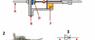
- Semiconductor - do not have switching contacts, the circuits are opened and closed by p-n-p and n-p-n junctions under the influence of control voltage. Varistors, thyristors, triacs and transistors are used as semiconductor elements.
- Induction - the control voltage in the winding is induced from an adjacent coil that is not connected by direct electrical contact;
- Magnetoelectric - the magnet occupies a stationary position in the structure, the coil with contacts on the frame rotates, closing or opening the circuit;
- Polarizing - work as electromagnetic direction of switching contacts will determine the polarity of the connection on the coil;
TYPES OF INTERMEDIATE RELAYS
The protection and automation circuits are powered from special operational current circuits. By type, the operating current can be alternating or direct.
Sources of direct operating current voltage can be batteries, capacitor banks or rectifiers; the alternating opercurrent busbars are powered by voltage from auxiliary transformers.
Since intermediate relays operate in operational voltage circuits, depending on its type, they are manufactured with coils for direct and alternating current.
RP – 23.
This type of intermediate relay is designed to operate in DC voltage circuits. RP – 23 consists of a voltage coil with a magnetic core. The moving part of the magnetic system is the armature, which, when voltage is applied to the coil, is attracted to the core.
A traverse is mechanically connected to the anchor, on which four contact bridges are attached. Being attracted to the core, the anchor lowers the traverse, compressing the spring on which it is installed. In this case, the normally open contacts close and the normally closed contact opens.
Fixed contacts RP-23 are made in the form of corners made of thin copper plates. Each corner can be installed in one of two ways. Thanks to this, it is possible to obtain four types of combinations of contact group options (p – opening group, z – closing group):
- 1 r, 4 z;
- 2 r, 3 z;
- 3 r, 2 z;
- 4 rubles, 1 z.
This invariance allows this device to be adapted to work as part of any circuit.
When opened, two air gaps are created for each contact, thereby increasing their arc-extinguishing ability.
This property is important when operating a relay device in trip circuits of high-voltage circuit breakers, the solenoids of which have high inductance and maintain the electric arc voltage when the circuit breaks. RP – 23 is available in various modifications for operation in operational circuits with voltages of 24 V, 48 V, 110 V and 220 V
RP – 23 is available in various modifications for operation in operational circuits with voltages of 24 V, 48 V, 110 V and 220 V.
RP – 25.
The internal electrical connection diagram of an intermediate relay of this type is similar to RP-23. The RP-25 coil is designed to operate on alternating voltage. Execution options are equipped with coils for voltages of 100 V, 127 V or 220 V.
The working life of the electromagnetic mechanism of the intermediate relays RP-23 and RP-25 is 100,000 operations. The contact group can withstand 10,000 closing and opening cycles with full electrical load in terms of current and voltage.
Explanation of the abbreviation of intermediate relays
To conveniently determine the functional purpose, number of contacts and other parameters, the relays have alphabetic and digital designations:
- P – intermediate;
- E – electromagnetic;
- 46 or (XX) – product series;
- 1 – pulse control signals.
Further designations may determine for what climatic conditions the product is adapted and the number of contact groups.
An example of how the symbols are deciphered
REP26-004A526042-40UHL4
- REP – electromagnetic intermediate relay
- Episode 26
- XXX – functional purpose and number of contacts
| appointment | Quantity | ||
| closing | opening | switching. | |
| 001 | — | — | + |
| 010 | — | + | — |
| 100 | + | — | — |
| 002 | — | — | ++ |
| 020 | — | ++ | — |
| 110 | + | + | — |
| 200 | ++ | — | — |
| 003 | — | — | +++ |
| 120 | + | ++ | — |
| 210 | ++ | + | — |
| 300 | +++ | — | — |
| 004 | — | — | ++++ |
| 220 | ++ | ++ | — |
| 310 | +++ | + | — |
| 400 | ++++ | — | — |
- 001 – means that the relay contains 1 switching contact, 010 – one breaking contact; 400 – four normally open contacts.
- A….D – wear resistance class of the materials from which the contacts are made;
- X – type of current in the winding of the electromagnetic coil, type of design for returning the mechanism to its original state,
1 – ~ current;
5 – direct current;
6 – direct current in the current coil;
- XX – two-digit digital code showing the design of mounting the relay housing on the surface and the method of connecting wires to the terminals:
| Code | connector | Wire connection method |
| 16 | —- | Solder |
| 18 | —- | "faston" |
| 76 | —- | seal |
| 21 | + | screw connections |
| 26 | + | solder |
| 78 | + | seal |
- XX – code indicating the magnitude, type of voltage, current in the coil winding
| Codes for electrical parameters of the closing coil | ||
| constant | ~ current 50 Hz | |
| 01…6 V 02…12 V 03…15 V 04…24 V 06…48 V 09…60 V 11…110 V 13…220V | 21…12 V 22…24 V 24…40 V 26…110 V 27…220 V 28…380 V 34…230 V 35…240 V | |
Codes from 01 to 13 indicate that the coils of these relays are DC with different voltages from 6 to 220V. Codes 21 to 35 indicate that the coils are rated for ~ I with U = 12…. 240 V frequency 50 Hz.
The last designation X indicates the presence of special elements in the design:
2 – manual relay switch;
5 – with manual manipulation and electronic relay position indicator for 24V products;
6 – with a manual manipulator and a diode to protect relays at 24V and less;
7 – the relay includes all three previously listed elements,
40 is the degree of protection from moisture and dust IP- 40...56..68;
UHL4 is a model for the corresponding climatic conditions, given for the north and middle latitudes. The letter “O” indicates that the product is adapted for the tropics.
REP26-004A526042-40UHL4 - this abbreviation indicates that the intermediate relay has 4 switching contacts with class A (wear resistance), direct current, contact connection with connectors, wires are secured by soldering, a 24 V coil, the design has a manual manipulator. Protection class IP – 40 for northern and middle latitudes.
Tip #1. Some people neglect the degree of protection of the product; relays have thin contacts and are sensitive to dust and humidity. Therefore, the degree of protection must be taken into account, especially in facilities with high humidity and dust. In explosive areas, it is recommended to use semiconductor products that do not spark during switching.
Despite the different designs and technical characteristics, all intermediate relays have basic common parameters by which compliance with the functional purpose is determined.
Types of intermediate relays
Intermediate relay on Din-rail
Based on their design, they are divided into relays for electromagnetic intermediate or mechanical and electronic devices. Mechanical relays can operate under different conditions. These are durable and reliable devices, but not accurate enough. Therefore, more often their analogs are mounted in the circuit - electronic relays on a DIN rail. The relay can also be installed on a flat surface. To do this, the lock latches need to be moved apart.
Based on their purpose, devices are divided into the following categories.
- Combined interdependent devices operating in a group.
- Logic devices that operate on microprocessors in a circuit with digital relays.
- Measuring, with an adjustment mechanism, triggered at a certain signal level.
According to the method of operation of the RP, there are direct ones, which directly open or close the circuit, and indirect ones, which work together with other devices. They do not open the circuit immediately after a signal is received.
There are devices of the maximum switching type, when operation occurs at the moment the threshold value of the circuit parameter increases. The minimum type is triggered during a decrease in characteristics.
According to the method of connection to the circuit, there are primary ones that can be connected directly to the circuit. Secondary ones are installed through inductors or capacitors.
Intermediate relay device
Despite the large number of varieties of relays of this type, their design is largely similar. The basis of the device is the control solenoid; it also consists of contacts, a core and a spring. Depending on the current and voltage ratings, as well as the type of circuit - alternating or direct current, various models of intermediate relays are produced.
There are no external differences in the design. The main difference is in the material of the magnetic core - in relays for alternating current, the core is made up of separate steel plates, while for direct current it is made of all metal.
Thanks to this design solution, energy losses due to heating of the steel core of plates through which alternating current passes are reduced.
Electromagnetic intermediate relays
RP series relays are manufactured in modifications for alternating and direct current. The design differences are very specific, not understandable to everyone, and are not of great interest. The AC relay RP-25 is similar in structure to the RP-23. The anchor is located on the side, not on top. Alternating current creates a field that gives the magnet greater acceleration. Therefore, there is no need for the actuation of the relay to be assisted by the armature's own weight.
Depending on the design features, the process of setting up the product differs. For each type of relay, it follows its own circuit, described in the instructions. We will find information in reference books. One relay can operate at different voltages. This is achieved by winding the appropriate number of turns on the working coil and varying the core diameter. The higher the voltage, the more turns you take, the thinner they are. It is necessary to reduce the flowing current and reduce the magnetic field strength. This will allow the anchor not to be affected by modernization.
For craftsmen, reference books will contain information about the brand of winding wire. For RP-25 single-core PEV-2 with two-layer viniflex insulation.
In one electromagnetic relay, some of the contacts are making and some are breaking. It can be used indirectly to control the start of asynchronous motors. The joint operation of a large volume of technological equipment is impossible without intermediate relays. Simple, effective means will ensure system synchronization.
Characteristics
The characteristics significant for operation are as follows:
- type of current – alternating/direct;
- relay dimensions;
- maximum duration of relay operation;
- switching current value;
- power consumption;
- operating voltage;
- values of minimum and maximum operating temperatures;
- relative humidity, dust concentration and vibration level at which operation of the relay is permissible.
For ease of use, part of the relay is equipped with connectors for DIN rails. There are many options for the location of device connectors for this type of mounting.
Relays with different current and voltage ratings are manufactured with different contact arrangements to eliminate the possibility of replacing a failed relay with another one, but with unsuitable parameters.
Operating principle of the intermediate relay
As soon as current arrives at the coil, the armature is retracted under the action of the resulting electromagnetic force, closing the movable contacts on the armature and the fixed contacts on the body. When the contacts close, the control circuit is turned on. This could be a protection system, an alarm system, or an electric motor starting circuit. Depending on the purpose of the relay, there may be several groups of contacts.
Purpose of the intermediate relay
An intermediate relay is a device that ensures the operation of several electrical circuits.
This is an auxiliary device that is designed to control the operation of various machines and complexes. Ensures the operation of several electrical circuits at once when it is necessary to simultaneously switch different contacts.
For example, one of the contacts should display an alarm signal on the relay screen, and the other should turn off. Either one connection starts the machine, the other turns off another part of the device.
An intermediate relay (IR) is also used to slow down the reaction at the required high loads. For monitoring a main relay that switches large currents under high voltage conditions.
An intermediate relay is called because in the control circuit it is located between the pulse source it controls and the power executive circuits.
Purpose and scope of intermediate relays
It is difficult to list the industries in which intermediate relays are used. In all industries, devices for household use, especially in elements of systems with electronic and electrical equipment, an intermediate relay can be installed.
There are several cases where auxiliary relays are used in complex electrical systems:
- For switching sections in various networks independent from each other;
- To increase the response delay of protective elements in circuits with high load currents;
- In secondary circuits, to control the parameters and operating modes of individual elements in high voltage circuits;
One relay on a production line can perform several switching operations simultaneously or sequentially in power or control circuits. In heating and water supply systems, when the deep-well pump is turned on, power is supplied to the relay coil, and when the group of contacts is closed, the control system for the operation of the pump is turned on. The operator’s display displays the main parameters: the presence of voltage on the pump, load currents in each phase, temperature and others, depending on the complexity of the circuit, as necessary.
The other pair will simultaneously close the power supply contacts to the coil of the magnetic starter, when triggered, the current will flow to all three phases of the pump motor. If the starter is assembled using a reversible circuit, another group simultaneously turns off the reversible circuit, eliminating a short circuit.
In a heating system, a signal with weak currents is not capable of turning on the coils of powerful magnetic starters or relays. Therefore, the intermediate relay acts as an amplifier of the control signal; the signal from the heat sensor turns on the intermediate relay, the contacts of which supply voltage to the windings of the magnetic starter, the contacts of which close and power is supplied to heating elements, boilers or other powerful heating devices.
When operating intermediate relays, the following aspects are taken into account:
- maintenance personnel need to carefully monitor the condition of the intermediate relay: daily visually assess the appearance of the device, remove any contamination, check and clean the contact connections. If mechanical damage is detected, you need to seek help from specialists;
- the operating temperature range, humidity and dust levels must comply with the requirements specified in the recommendations for the operation of the intermediate relay. Otherwise, there is a high probability of its incorrect operation or premature failure;
- if the intermediate relay is used in an industrial environment, it must be equipped with special blocks designed for installation on a DIN rail.
Ways to turn on the device
How to connect the mechanism to the system? Connecting the device to the electrical circuit occurs in two ways:
- Parallel connected. With this method, there are main output and high-speed devices. The latter have a response time of 0.02 seconds. As a rule, the mechanism has a standard response time that ranges between 0.02 and 0.1 seconds.
- Serially connected. Used in cases of instantaneous short-term operation.
When there is a normal stable voltage from the power source, the intermediate relay should operate reliably. In addition, their reliable operation is provided during an emergency voltage drop to 40–60%. By design, such a conversion element can have one, two or three windings (the latter are extremely rare).
Connecting an intermediate relay is important for any equipment or device. After all, this allows you not only to automatically interrupt the circuit, but also with its help you can expand the functionality of other relays that are located in this electrical circuit.
The durability of the device depends on the number of times it is triggered. That is, it is characterized by the number of operation cycles and a return to its original position. The degree of protection of the equipment from various undesirable factors that surround the structure is assessed by such a criterion as the time of transition of contacts from one position to another.
Connection diagrams
After the intermediate relay has been installed in the electrical cabinet, it should be connected to the electrical circuit. For this purpose, the contacts of the coil itself and direct contact elements are used. The relay usually has several pairs of NO normally open and NC normally closed contacts. The normal position is considered to be the absence of a signal to the coil. Since the coil does not have polarity, the contacts are connected arbitrarily.
Such a device is installed in control and automation circuits. Located between the actuator (for example, a contactor) and the reference source. The figure shows the electrical diagram of the device:
The picture shows an intermediate relay without voltage supply. If you apply it, the contacts will switch. The voltage in the coil can be different: 220, 24 and 12 volts.
How to connect the device is shown in the figure below:
In some cases, an intermediate type relay is used as a contactor, then the installation diagram will look like this:
As you can see, the intermediate relay has three groups of contacts that control the load and one group to hold the current in the coil. You can install an additional contactor, then the device is connected first to the contactor.
This device can also be connected to a motion sensor. Thanks to it, it is possible to connect several powerful lamps to the motion sensor system. Installation occurs as follows: the winding of the device is connected to the sensor, and the power contact switches the load in the lighting system. How to install such a sensor is shown below:
Another option for installing an electronic starter is to a thermostat. The diagram is shown in the picture (click to enlarge):
In this case, the thermostat and starter are connected in sequential order to the first phase and neutral wire (in the diagram they are designated as T1 and K1, respectively). The installation of the remaining contacts of the starter is carried out evenly between other phases.
Operating principle of the intermediate relay
A relay with normally open contacts consists of a winding, magnetic circuits of reed switches and housing parts. An intermediate relay, equipped with normally open contacts, contains permanent magnets. On top of the relay frame there are brackets that are designed for attaching external wires under screws. The lower part of the housing is necessary for mounting the relay on the plate. Applying voltage to the winding causes the reed switches to close in a relay that does not contain a permanent magnet, and the reed switches to open in a relay that contains permanent magnets. After removing the voltage relay from the winding, the reed switches return to their original position.
Connection and adjustment nuances
After installing the intermediate mechanism, it must be connected to the electrical circuit. For this, coil contacts will be used, as well as additional connecting elements. Typically, the device has several contact pairs: NO - normally open and normally closed (NC).
Distribution of groups in the presented electrical circuit: 10-11 – normally closed contacts; 11-12 – normally open; contacts 1 (phase) – 3 (zero) – relay supply voltage
In the first position, it is assumed that the signal to the coil is completely deprived. Since there is no polarity, the internal connection of the contact group can be performed in a chaotic manner.
To connect the review mechanism, consider the schematic instructions. The expected voltage in the coil can be: 12, 24 or 220 V.
Electrical diagram of the device without connection to the network. Its installation is carried out in control and automation circuits. Location – between the main executor and the source of the task
We will analyze the regulation of the electronic starter using the example of the most common model RP-23.
The process consists of the following steps:
- By checking the start and return voltage with the supply of a galvanic current source to the coil, we carry out gentle regulation.
- At the moment of attracting the armature, the moving unit of the system should have a joint stroke of 0.1-1.5 mm. We carry out the correction procedure by bending the shank onto an L-shaped plate.
- Between the active and inactive contacts, the gap level is set within the range of 1.5-2.5 mm. The deflection is adjusted by pressing the square of the fixed contacts and the upper stop of the moving system.
- At the final position of the armature (closure), the dip of the inactive contacts will be 0.3-0.4 mm.
- In the middle of the plane, the moving and fixed contacts must coincide. The adjustment is made by moving the plate and guide bracket.
The same method is used to reproduce the settings of the RP-25 relay, however, the gap between the coil with the core and the armature in the attracted state is eliminated.
Relay contacts.
Depending on the design features, the intermediate relay contacts are normally open
(closing),
normally closed
(breaking) or
changeover
.
3.1. Normally open contacts.
As long as the supply voltage is not applied to the relay coil, its normally open contacts are always open
.
When voltage is applied, the relay is activated and its contacts close
, completing the electrical circuit. The pictures below show the operation of a normally open contact.
3.2. Normally closed contacts.
Normally closed contacts work the other way around: as long as the relay is de-energized, they are always closed
.
When voltage is applied, the relay is activated and its contacts open
, breaking the electrical circuit. The pictures show the operation of a normally open contact.
3.3. Changeover contacts.
For changeover contacts with a de-energized coil, the average
the contact attached to the anchor is
common
and closed with one of the fixed contacts. When the relay is triggered, the middle contact, together with the armature, moves towards the other fixed contact and closes with it, while simultaneously breaking the connection with the first fixed contact. The pictures below show the operation of a changeover contact.
Many relays have not one, but several contact groups, which makes it possible to control several electrical circuits simultaneously.
There are special requirements for intermediate relay contacts. They must have low contact resistance, high wear resistance, low tendency to weld, high electrical conductivity and long service life.
During operation, the contacts with their current-carrying surfaces are pressed against each other with a certain force created by the return spring. The current-carrying surface of a contact in contact with the current-carrying surface of another contact is called the contact surface
, and the place where the current passes from one contact surface to another is called
electrical contact
.
The contact of two surfaces does not occur over the entire apparent area, but only in separate areas, since even with the most careful treatment of the contact surface, microscopic tubercles and roughness will still remain on it. Therefore, the total contact area
will depend on the material, the quality of the contact surfaces and the compression force. The figure shows the contact surfaces of the upper and lower contacts in a greatly enlarged view.
At the point where current passes from one contact to another, electrical resistance occurs, which is called contact resistance
. The magnitude of the contact resistance is significantly influenced by the magnitude of the contact pressure, as well as the resistance of the oxide and sulfide films covering the contacts, since they are poor conductors.
During long-term operation, the contact surfaces wear out and can become covered with soot deposits, oxide films, dust, and non-conducting particles. Contact wear can also be caused by mechanical, chemical and electrical factors.
Mechanical wear occurs when contact surfaces slide and impact. However, the main cause of contact destruction is electrical discharges
, arising when opening and closing circuits, especially DC circuits with an inductive load. At the moment of opening and closing, the phenomena of melting, evaporation and softening of the contact material, as well as the transfer of metal from one contact to another, occur on the contact surfaces.
Silver, alloys of hard and refractory metals (tungsten, rhenium, molybdenum) and metal-ceramic compositions are used as materials for relay contacts. The most widely used material is silver, which has low contact resistance, high electrical conductivity, good technological properties and relatively low cost.
It should be remembered that there are no absolutely reliable contacts, therefore, to increase their reliability, parallel and serial connection of contacts is used: when connected in series, the contacts can break a large current, and parallel connection increases the reliability of the electrical circuit.
What is a bistable relay
A bistable relay is one of the names for a pulse relay. This is a type of relay that switches the power contact when an instantaneous pulse is applied to its coil. Pulse relays come in electromechanical and electronic control types.
They differ in the principle of their design.
For an electromechanical relay, the device includes a contact system, a coil, lever and spring systems, a breaker and a switch. With this type of relay, a short-term pulse is usually applied to the coil at the time of energy consumption, that is, during operation. And the electronic pulse relay has a board with an electromagnetic relay microcontroller installed. There are different manufacturers of impulse relays.
A bistable relay switches the power contact when an instantaneous pulse is applied to its coil
Among the most famous at the moment are:
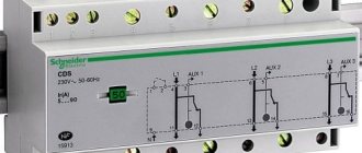
- Schneider Electric;
- ABC;
- F&F;
- Meander.
There are also different options among the models, but today we’ll look at the example of the RIO-1M 220V pulse relay, manufactured by Meander. At the moment, this device can be purchased for 1000 rubles. This particular model is an improved version of its predecessor RIO-1. It is designed to control the lighting of entire circuits of lighting devices. Control is carried out using backlit connecting buttons. RIO-1M is installed on the electrical panel on a DIN rail. The design is modular.
Operating principle of an impulse switch
As noted above, a non-automotive impulse relay has a clear advantage over its conventional options. The advantage is that impulse relays do not need a constant supply of energy.
System:
- Closes open contacts (or opens closed ones) when the current level exceeds a threshold value, that is, when the coil activates the mechanism.
- When electrical power is supplied, a magnetic force is generated that operates the switch mechanism.
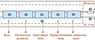
- The stepper relay circuit consists of a control circuit and a load circuit.
The relay consists of an electronic coil and a sensor unit, which are respectively powered. The second circuit is responsible for the memory state of the pulse relay. From this we can draw a small conclusion that the relays have a memory of the state of the network, as well as connection data.
Operating principle of an impulse switch
By the way, this device is silent.
The bipolar relay has a large field of action, which allows you to control lighting in large rooms. It was invented so as not to walk around the entire perimeter, pressing each switch. This is a very convenient device.
How to make a bistable relay with your own hands
To connect this device, it is best to take a monostable relay with a timer (5, not two-pin, 3777). The nature of the switch means that it can be used in different ways. You need to use the Legrand or Schneider scheme. A double-pole relay needs 2 switches, while a single-pole relay needs one. Therefore, it is necessary to purchase a bistable relay, as well as a box for it. At the moment of fixation, a short-wave pulse will be triggered during the signal arrival. In this case, the input contacts are fixed in the closed, on position, and when the next pulse occurs, they will turn off, and then the contact to the second output of the relay device will be fixed.
In this case, 2 timer ranges are used - from 0 to 1 sec, from 1 to 100 sec.
In principle, you can set up absolutely any mode, but if the installation is in large rooms, then it is better, of course, to use a timer with a large interval, and if for a dacha or a small area - with a small one. There are 2 groups of wires that are supplied with - heavy wire for the output and lighter, lighter wire.
You can make a bistable relay yourself
If we use the ABBBE wire system (and not ABB ), then the diagram will be as follows:
- Cable 1 (input, three-pin connector);
- Red (for reuse of internal systems);
- Black (12 volts – ground).
So, green (input trigger provides an incoming pulse to control the signal. This line can be drawn on one side with a special spring switch, and on the other side - a + or - contact (power source, for example, a battery). The same thing is used by automobile concerns, for example , for fog turns. Cable 2 (output, two-pin) - brown (depending on the polarity of yellow, we connect to +12V or -12V and yellow (controls power, we connect it to black (ground) and brown). The mechanism is activated during the initial press The front contacts are switched on after the rear contacts are closed.
Operating principle of a pulse relay
Impulse relays have a strong advantage over conventional relays because they do not require a constant supply of power or voltage in order to operate as needed. Due to their energy, which is quite efficient, switching trimmers are used in a huge variety of electronic devices.
Pulse relay circuit
All relays contain a sensor unit and an electric coil, which is powered by an AC or DC power source. When the applied current or voltage level exceeds a threshold value, the coil activates a mechanism that acts to close open contacts or open closed ones. When power is applied to the coil, it generates a magnetic force that operates the switch mechanism. Magnetic force is essentially a transmitting action from one circuit to another. The first circuit is called the control circuit, and the second is the load circuit. Due to the fact that pulses are produced almost exclusively using electromagnetic fields, this device is silent.
The second circuit is also responsible for the state of the relay memory. The fact is that any modular low-voltage relay is equipped with a memory mechanism. Those. The device stores the latest data about connections, network status and operation.
Basically, most of us have a question: why do we need a relay if you can control the lighting using a regular pass-through switch? The fact is that even the simplest relay has a much wider range of action; with its help you can control lighting from three or more places, without making much effort to connect it. Let's look at the types of relays.
Relay type
This electronic device comes in several types:
- pulse electromagnetic relay bistable type 411, capable of transmitting up to 12V. The buttons of this device are connected in parallel to each other, and when the contacts close in one place, the electrical circuit automatically opens them in another. You can switch in any convenient way. The main advantage is cable savings; there is no need to branch the wiring in the apartment;
Impulse relay bis-414 - bistable device 413. Here, a special circuit is responsible for control, which itself turns off the light after a certain period of time. This system is often used in catering establishments, where customers often simply forget to turn off the lights. In some individual cases, switching off occurs when the button is pressed again, although this mechanism is also adjustable;
- analogues of the above devices are devices of the 414 and 412 series. These are devices that combine the characteristics of the two previous devices. The key feature of their operation is that they provide power not only from two sides of the passage, but also from two loads, i.e. they can be connected to two different wiring, say a lot of horn chandeliers, elevators, etc. From a mechanical point of view, they are more efficient and durable.
Pulse relay bis-411
The vast majority of the relay works with various neon lights, LED lamps and other small and relatively unloaded lighting devices. But, unfortunately, the simplest pulse group or bistable relay, for example, models from legrand, acti, Colan, dc, electric Schneider, gerin, general, esmi etimat, fotek, fujitsu, hager, moeller, iek, itl, merlin, multi , pulsar, sassin, Siemens, tlc, zamel, finder, their cost is about 1000 rubles (although the price of domestic ishm is slightly lower - from 700 rubles). Therefore, we will tell you how to assemble such a device at home.
How to make a pulse relay yourself
We propose to use a solid-state polarized relay with a timer as a basis for work. As an example, this could be an instant response device with a power of 12v. The programmable nature of this switch means that it can be used in a variety of ways. You can use the Legrand or Schneider circuit, depending on the needs of the machine.
A double-pole latching relay needs 2 switches to operate, but a homemade single-pole relay requires polarity reversal to operate. You need to buy not only a pulse relay, but also a box for it (visit any electrical store in your city - Kiev, Moscow, Perm, St. Petersburg, Kharkov, Yekaterinburg, Dnepropetrovsk). Our device has the following characteristics:
- 0.03 mA and 12v (this is an excellent circuit for solar panels)
- Output current – 7 a;
- Four switches.
In latching mode, this will cause an instantaneous pulse whenever a signal is received. In this case, the contacts of the trigger input are fixed in the closed on position; as soon as the next pulse occurs, they turn off, and the contact on the second output of the relay is fixed in the same way.
There are two timer ranges, zero to 1 second, or 1 to 100 seconds. You can set up absolutely any mode, but for industrial buildings it is much more profitable to connect devices or systems with a large period of time, but for domestic use - with a minimum.
The unit comes with 2 sets of wires, one for the output (heavy gauge wire, 7 amp) and one for the input control (lighter wire, fused into 3 amps). Here is the basic information on how to connect a small-sized pulse relay with abb type wires:
- Cable 1 (INPUT: 3-pin):
- Red: +12 Power for reuse operation of internal circuits (3 A fuse)
- Black: 12v ground
Green: Trigger input, provides an input pulse to control the latching operation. You can connect this line on one side with a spring push-button switch, and on the other side using a + or - contact with a power source (it all depends on the purpose, you can also use a car battery, as the auto concerns Volga, Gas, VAZ and others that use relays for fog turns, general light in cars, alarms, etc.).
Pulse relay contacts
Cable 2 (OUTPUT: 2-pin):
- Brown: connect to +12 volts or -12V depending on the polarity of the yellow wire;
- Yellow: This is load power control, need to connect it with brown wire and ground
In principle, this is a standard design, the most difficult thing about it is choosing a counting-wire and latching relay.
Activation occurs when the switching mechanism is pressed for the first time. The front contacts are switched on as soon as the rear contacts are closed. When finishing reading our course on connecting relays, don’t forget to watch the detailed video.
Sources
- https://220.guru/elektrooborudovanie/avtomaty-uzo/promezhutochnoe-rele.html
- https://sovet-ingenera.com/elektrika/rele/promezhutochnoe-rele.html
- https://electrikexpert.ru/chto-takoe-promezhutochnoe-rele/
- https://electric-tolk.ru/podklyuchenie-promezhutochnogo-rele/
- https://www.Reform-market.ru/stati/promezhutochnye-rele/
- https://elektrik-sam.ru/jelektrooborudovanie/rele-kontaktory-datchiki/3966-kak-podkljuchit-promezhutochnoe-rele.html
- https://6watt.ru/elektrooborudovanie/rele-i-datchiki/impulsnoe-rele
- https://www.asutpp.ru/impulsnoe-rele.html