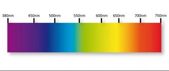
Distribution environment
The propagation medium is the space in which the wave features of the electromagnetic field appear.
The electromagnetic field can propagate in the following media. 1. In free space, characterized by dielectric constant $$\begin{equation}\varepsilon_0=\left(\frac{1}{36\pi}\right)\cdot{10^{-9}}\approx{8.854\ cdot{10^{-12}}} \end{equation}\tag{2.1}$$
and magnetic permeability $$\begin{equation} \mu_0=4\pi\cdot{10^{-7}} \end{equation}\tag{2.2}$$
2. In an ideal dielectric [i.e. i.e. in a lossless dielectric medium (σ=0)], characterized by relative permittivity εr and relative magnetic permeability μr, for which, therefore, the electrical permittivity $$\begin{equation} \varepsilon={\varepsilon_r}{\varepsilon_0} \end{equation}\tag{2.3}$$
and magnetic permeability $$\begin{equation} \mu={\mu_r}{\mu_0} \end{equation}\tag{2.4}$$
3. In media with losses due to the presence of conductivity, characterized by relative permeability $$\begin{equation} \varepsilon_r^\prime=\varepsilon_r-{I}{60}{\lambda_0}{\sigma} \end{equation}\ tag{2.5}$$ where λ0 is the wavelength in vacuum. For these media, ε'r is complex.
In table Table 2.1 shows the values of εrμr and σ for some media. These values are valid in the VHF band.
4. In environments with high conductivity (a special case of paragraph 3).
characterized by a large value of the complex part ε'r. Table 2.1. Values of parameters εr, μr and σ for some media
| Distribution environment | εr | μr | σ |
| Air | 1 ,0005 | 1 | 0 |
| Fresh water | 81 | 1 | 10-3 |
| Sea water | 80 | 1 | 4 |
| The soil is wet | 10 | 1 | 10-2 |
| Dry soil, sand | 4 | 1 | 10-3 |
| Rocky ground | 10 | 1 | 10-3 |
| Snow | 1,4 | 1 | 10-3 |
| Ice | 3,2 | 1 | 10-3 |
| Forest | 10 | 1 | 10-3 |
| Urban area | 3 | 1 | 10-4 |
The propagation medium is homogeneous if its parameters ε, μ and σ do not change along the direction of propagation of electromagnetic energy. A propagation medium for which the parameters ε, μ and σ do not depend on the direction of propagation of electromagnetic energy is usually called isotropic. In contrast, a medium whose parameters depend on the direction of wave propagation is called an anisotropic medium. An example of the latter is the ionosphere.
In addition, one should distinguish between dispersive and non-dispersive media, i.e. media for which the parameters εr, σ and μ depend or do not depend, respectively, on the frequency of the electromagnetic oscillation. The ionosphere can also serve as an example of a dispersive medium.
Digital library
Life safety in the technosphere / Non-ionizing electromagnetic fields and radiation. Part 1. / 3.2.3. Household magnetic field sources
All household appliances that operate using electricity are sources of electromagnetic fields of the widest frequency range, including industrial frequency.
The following devices can be considered the most powerful of them: microwave ovens; air fryers; refrigerators with a “no frost” system; kitchen hoods; electric stoves; TVs.
At the same time, the magnitude of the electric field strength of industrial frequency in almost all electrical household appliances does not exceed several tens of V/m at a distance of 0.5 m, which is significantly less than the maximum limit of 500 V/m.
As for the values of magnetic induction (magnetic field strength), they are also small. However, according to modern ideas, a magnetic field of industrial frequency can be dangerous to human health
, if prolonged exposure occurs (
regularly, at least 8 hours a day, for several years
) with a level
above 0.2 μT
[110]. Household appliances can create a magnetic field of industrial frequency, the intensity of which is higher than the specified value (Table 3.1 [110]).
Table 3.1 The magnitude of the magnetic field created by household appliances
| Device | Magnetic field induction V, T |
| 1 Microwave oven | 4 – 12 |
| 2 Drill | 2.2 – 5.2 |
| 3 Electric stove | 0.4 – 4.4 |
| 4 Mixer | 0.4 – 2.2 |
| 5 Vacuum cleaner | 0.2 – 2.2 |
| 6 Iron | 0 – 0.4 |
| 7 Washing machine | 0 – 0.3 |
| 8 TV | 0 – 0.2 |
| 9 Coffee maker | 0 – 0.2 |
In table Figure 3.2 presents data on the distance at which a magnetic field of industrial frequency (50 Hz) of 0.2 μT is detected during the operation of a number of household appliances [110].
In addition to the household appliances themselves, a powerful source of industrial-frequency magnetic fields is the electrical equipment of the building (cable lines supplying electricity to all apartments and other consumers of the building’s life support system, as well as distribution boards and transformers).
Table 3.2 Propagation of the industrial frequency magnetic field from household electrical appliances (above the level of 0.2 µT)
| Source | The distance at which a value greater than 0.2 µT is recorded |
| Refrigerator equipped with a system “No frost” (during compressor operation) | 1.2 m from the door; 1.4 m from the back wall |
| Normal refrigerator (during compressor operation) | 0.1 m from the motor |
| Iron (heat mode) | 0.25 m from the handle |
| TV 14″ | 1.1 m from the screen; 1.2 m from the side wall |
| Electric radiator | 0.3 m |
| Floor lamp with two 75 W lamps | 0.03 m (from wire) |
| Electric oven | 0.4 m from the front wall |
| Air fryer | 1.4 m from the side wall |
In rooms located near these sources, the level of the industrial frequency magnetic field is usually increased.
So, in Fig. Figure 3.20 shows [110] the distribution of the industrial frequency magnetic field in a residential premises, which is adjacent to a non-residential premises containing a power distribution point.
Rice. 3.20. Distribution of a magnetic field of industrial frequency in a residential premises, which is adjacent to a non-residential premises
In Fig. Figure 3.21 shows [110] the distribution of the magnetic field of industrial frequency in a residential building, along the outer wall of which a cable line runs.
Rice. 3.21. Distribution of a magnetic field of industrial frequency in a residential building with a cable line running along the external wall
As can be seen from the figures, in a certain part of the living room the level of the magnetic field can significantly exceed the value of 0.2 µT.
Excitation of electromagnetic waves
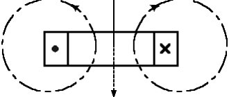
Around a conductor through which current I flows, caused by voltage U, a magnetic field with intensity H and an electric field with intensity E are created. The magnetic field lines H form concentric circles around the conductor and lie in a plane perpendicular to the axis of the conductor. Electric field lines E are perpendicular to magnetic field lines H and lie in a plane passing through the axis of the conductor (Fig. 2.1).
A change in current over time leads to a change in time in the electric and magnetic fields. The change in current over time can be, for example, pulsed in nature or subject to another selected modulation law. Each such non-sinusoidal process of changing the current level can be, based on the Fourier expansion known from mathematics, represented as a sum of sinusoidal oscillations of multiple frequencies with different amplitudes for each frequency. Therefore, in the future we will limit ourselves to considering only sinusoidal processes.
Caused by a change in current in a conductor, the time-varying electric and magnetic fields are, in fact, a single changing electromagnetic field propagating in space. A time-varying electromagnetic field propagating at speed v can be considered an electromagnetic wave.
An electromagnetic wave is characterized by the following parameters.
1. Direction of propagation (ray)—the line along which the electromagnetic wave propagates. In a homogeneous isotropic medium, the direction of propagation is a straight line emerging from the radiation source. In a number of cases that are interesting from a practical point of view, the direction of propagation can be characterized by a smooth or broken curve.
2. Phase front - the geometric location of points at which the oscillations have the same phase. For a plane wave, the phase front is a plane perpendicular to the direction of propagation. For a wave excited by a point source, the phase front is a sphere.
3. Polarization - the orientation of the electric field strength vector E relative to the direction of propagation.
Electromagnetic waves for dummies. What does the phone emit?
Last updated:1 day ago
Reader rating for this article: 4.9
(69)
In this short series of three articles, we will try to understand a very important topic that concerns every modern person. After all, we are all literally immersed in an ocean of electromagnetic radiation, sometimes without even realizing what it is and how it affects us.
Of course, there are plenty of articles on the Internet that talk about electromagnetic waves, their length and frequency, ionizing radiation and other complex terms. But for many people all this remains a mystery - something far from the reality that can be touched, seen, or at least realized.
For example, many people know that visible light is a stream of photons or “glowing balls” that transfer energy in space. But then are radio waves or heat also photons/balls?
How do you imagine energy? Could it be some kind of glowing clot of matter or a small portion of electricity, like microscopic lightning? But a thrown stone also has energy, but there is no electricity or luminous substance in it.
What happens when a smartphone or fitness bracelet creates an electromagnetic wave, which then transfers this energy to our body? After all, all these devices continuously emit something. And where does this energy go?
The purpose of this short series of articles is to answer all the questions posed above. But not to answer with numbers or complex terms, but to give an intuitive understanding so that electromagnetic radiation and energy seem as ordinary things as fire or water.
In the process of reading these articles, you will directly feel what it means to spend 1 joule of energy or how much 1 watt is. After all, it is in watts that the power of radio emission from Wi-Fi, smartphones or Bluetooth headphones is measured.
But before we understand the energy that various equipment emits (in the second part) and understand the influence of this energy on the body (in the third part), we need to understand what radiation is in general.
It is the nature of electromagnetic waves that will be discussed in the first article!
What is an electromagnetic field? Or about logical contradictions
Obviously, electromagnetic fields are a collection of electric and magnetic fields. But when trying to answer the question of what an electromagnetic field is, what it consists of, and why it works the way it does, we are faced with a logical contradiction.
If you tried to figure this out, then, most likely, you were also disappointed in the answers every time, because by asking such questions, you violate the laws of logic.
What is air made of? Obviously from molecules. Why does the air heat up? Because molecules are in continuous motion and if they accelerate, then when they collide with our skin they hit it harder, transferring part of the energy of movement to our molecules. And we feel warm.
These are simple questions and they have simple answers, since neither air nor molecules are fundamental concepts, which means their nature can be explained.
A fundamental concept is what everything else is made of, something that cannot be broken down into its component parts, cannot be divided, just as we divide molecules into atoms, atoms into electrons and nuclei, and nuclei into protons and neutrons.
Imagine a car assembled from designer parts. For a child, one detail will be a fundamental concept. After all, he doesn’t even imagine that a part can be “disassembled” into smaller “parts” - atoms.
So, in modern science, no matter how advanced and fantastic it may seem to us, electric and magnetic fields are fundamental concepts. Therefore, no article can give you the answer you are hoping for.
However, we can understand something!
What is an electric field?
All matter in our universe is primarily made up of three particles: electrons, protons and neutrons. These are the “indivisible” parts of the designer. And since they are indivisible, that means they are elementary.
Of these three particles, only two (electrons and protons) have something interesting called electric charge. For example, particles have some kind of mass, “size” and other parameters, including that same “charge”.
If you thought about electric current when you heard the word “charge,” you again made a logical mistake. Current is the movement of charges in space. Accordingly, when we call a charge a current, we go around in a circle: a charge is a current, and a current is a charge. Nonsense.
The fact is that the electron and proton do not just float in space, they change it! These particles create a certain form of matter around themselves, which we call an electric field.
It cannot be touched, it cannot be seen, but all particles with a charge experience its influence on themselves.
Electric charge is the ability of a particle to create matter around itself called an “electric field,” as well as the ability to respond to electric fields created by other particles.
If we imagine protons and electrons as balls, then the electric field will be the lines coming out of (or entering) these balls. These are not simple lines, they can push or attract other particles with a charge:
Electric field lines around charged particles
These lines never cross. If you place two protons next to each other, from which the lines (electric field) emanate, the lines will bend and try to straighten out, like rods. As a result, two particles will fly away from each other:
But if we put a proton, from which the lines come, and an electron, into which the lines enter, they will “stick” to each other:
When people noticed this behavior, they decided to somehow name the two types of such charges. You could call them outgoing and incoming charges, or sticky and prickly. But Benjamin Franklin (the one on the $100 bill) called them positive and negative charges.
So, the electric field is a kind of mysterious matter that is created around itself by all particles that have such a property as an electric charge.
Of course, in reality the electric field does not consist of physical lines, but this is the easiest way to represent this matter. For example, around particles with a positive electrical charge, the lines are directed away from the particle and this direction shows in which direction other positive charges will be repelled:
The closer to the proton, the more lines there are, that is, the higher the density of their placement and, accordingly, the electric field will be stronger. The further away from the proton, the rarer the lines are, and the weaker the field, that is, it pushes other charges with less force. This is even intuitively clear, since one bent “rod” will push a particle much weaker than a hundred of the same stretched “rods” made from matter unknown to science.
It is important to understand that the “twigs” do not directly push the particles; they do not affect them at all. These "rods" interact only with other "rods" or electric field lines created by other charged particles.
Therefore, if a particle has no charge (for example, a neutron), then it will not react in any way to electric fields in space and will not create this matter around itself.
The same applies to many atoms that have the same number of opposite charges (protons and electrons). Such atoms are electrically neutral, since some charges cancel out others. This becomes more clear if we call charges positive and negative, because +1 and -1 add up to 0.
What kind of substance the electric field consists of and what it looks like are meaningless questions. The field cannot consist of matter by definition. After all, our universe consists of matter, which in turn is divided into matter and field:
So you don't need to think of an electric field as a substance like electrons, atoms, or a liquid. This is a separate form of existence of matter. If there can be emptiness (vacuum) in a substance, then there cannot be emptiness in the field, since the field does not consist of individual particles.
Imagine that all space in the universe, including vacuum, is filled with some medium unknown to science. This is not an electric field, but simply something that fills everything around. In this case, an elementary particle with an electric charge will deform this medium. And this deformation/change in space is the electric field.
What is a magnetic field?
Since elementary particles with an electric charge create an electric field around themselves, then there must be elementary particles with a magnetic charge and it is they who create a magnetic field around themselves?
Although there is logic in this, it is not true. There is no such property of particles as a “magnetic charge” and not a single particle has a magnetic field. Where does it come from?
First of all, a magnetic field is another really existing type of matter that can appear from “nowhere” and disappear into “nowhere.” This is about the same change in space as the electric field, but with slight differences.
Let's take the electron for example. It is a particle that has an electrical charge. And if so, it always creates an electric field around itself and nothing else. But as soon as the electron moves from its place, that is, begins to move, around this electron, in addition to the constant electric field, a magnetic field will immediately begin to appear:
The electric field during electron motion is not shown in the picture
As soon as the electron stops, the magnetic field disappears. Unlike an electric field, a magnetic field does not emanate from the particle, but surrounds it. Also, the magnetic field lines are closed and not directed in all directions (the effect of their force is shown by the arrow in the picture above).
When an electron or other charged particle flies by, the magnetic field does not disappear instantly, but, as it were, stretches in a small trail in front and behind the electron, and the field is stronger the closer it is to the particle:
If an electric field acts with force on particles with an electric charge, then a magnetic field acts on the same particles if they are in motion.
For example, we can take two wires and run a current through them so that elementary charged particles (electrons) crawl along the wires inside. As soon as they begin to move, magnetic fields will appear around the wires. That is, two wires will literally become two magnets.
If the electrons in two wires move in the same direction, the magnetic fields will attract each other, as if you were applying two magnets with opposite poles. If the current in two wires flows in different directions, the “magnet wires” will repel:
Notice that the electrons' electric fields have nothing to do with this repulsion or attraction. This is where magnetic fields appear.
What makes electrons crawl through wires? That's right - an electric field! Since a lot of negatively charged particles have collected at one end of the wire, and positively charged ones at the other, it is the electric field that attracts negative charges (electrons) to positive ones, causing them to crawl along the wire:
Electric field lines
These are electromagnetic fields.
But what does radiation have to do with it? After all, electric and magnetic fields only exist around particles, right?
What is electromagnetic radiation? Or how the phone works
Again our logic suggests a very simple answer. If the electromagnetic field exists only around elementary particles with a charge (electrons and protons), then electromagnetic radiation is probably the flight of electrons or protons.
Probably, during a call, the smartphone throws electrons stored in the battery into space, which then scatter in all directions and create electromagnetic fields around themselves as they fly. Right?
This may sound logical, but it is fundamentally wrong. Everything is much more interesting and complex.
The fact is that our universe is designed in such a way that a changing electric field generates a changing magnetic field, and a changing magnetic field generates a changing electric field.
To understand this set of words, let's look at a simple example.
Let's return to the wire, at one end of which many positively charged particles have collected, and at the other - with a negative charge. Since electric field lines always leave positive charges and enter negative ones, our electric field looks simplified like this:
Naturally, such a field affects all the electrons in the wire and causes them to move towards positively charged particles. But when all the negative particles move down, now there is a negative charge at the bottom, and a positive charge at the top. And now the electric field has changed its direction and looks like this:
This is a changing electric field . It constantly changes its direction (the direction of the lines of force) and strength.
Well, what about the magnetic field?
When an electric field causes charged particles to move, a magnetic field is created around this movement. Moreover, when all the electrons are at one end of the wire, the magnetic field disappears, because the movement of the electrons stops. And when the electrons begin to move in the opposite direction, the magnetic field increases again to its maximum:
Since the direction of movement of electrons changes each time, not only the strength of the magnetic field associated with the movement of electrons changes, but also the direction of its lines:
This is a time-varying magnetic field !
It turns out that we have a changing electric field, which generates a changing magnetic field. And as we remember, a changing magnetic field again generates a changing electric field. And then a real chain reaction occurs, like falling dominoes:
Even if the wire and any particles are removed at this moment, this will not stop the wave of one field being generated by another. Such a wave will rush through space at the speed of light, affecting all other charged particles along the way.
By the way, it is this change in the electric field that is shown on the graphs in the form of waves:
When the electrons start moving and gather at one end of the wire, the electric field on the graph moves upward and increases in strength. The electrons then begin to move in the opposite direction and the strength of the electric field on the graph begins to decrease until the electrons are collected on the opposite side of the wire.
Now the graph again shows the maximum electric field strength, but now directed in the other direction:
Sometimes the graph is drawn more correctly, since a magnetic field is added to it, which oscillates perpendicular to the electric field:
So, we see that the electromagnetic wave is not associated with the flight of electrons or protons. With the help of electrons, we only create a changing electric field at one point in space and it generates a chain reaction called electromagnetic radiation.
No substance is transported in space, there is simply a disturbance/oscillation of space or a conditional environment that fills all space.
This is exactly what smartphones, Bluetooth headphones or fitness bracelets do. Inside these devices there are antennas - small pieces of wire through which electrons run in one direction or the other. Because of this, an alternating electric field is created, which creates an alternating magnetic field and the reaction we have already discussed is started.
Now imagine that such a wave reaches another device. A piece of wire (antenna) inside it begins to experience the influence of an electric field. At first it has maximum strength and is directed downward. Naturally, all electrons experience this influence and, under the influence of force, begin to move in one direction.
Then the electric field fades and the movement stops, after which it turns in the other direction and all the electrons again begin to move in the opposite direction. And the movement of electrons is a current. As a result, electricity or a signal appears in the wire!
For the wire and electrons, it makes no difference whether we connected a battery (the source of the electric field) or whether this electric field came in the form of a wave, the main thing is that all electrons begin to experience a driving force.
This is how we can transmit energy over a distance, simply by sending oscillations in the electric field.
An electromagnetic wave has several properties. For example, the speed of wave propagation is 300 thousand kilometers per second (in vacuum). The wavelength is the distance between its successive peaks:
That is, this is the time during which the electric field changes its direction.
The wave also has a frequency, which tells us how often the direction of electron movement in the wire (or the direction of the electric field) changes.
If the direction of the electric field changes 50 times per second, then we have an electromagnetic wave with a frequency of 50 Hz, and if the direction of the current changes 2.4 billion times per second, then the electromagnetic wave has a frequency of 2.4 GHz. This is the frequency at which Bluetooth, Wi-Fi and microwaves operate.
the energy of the wave depends on the frequency . Some waves can literally destroy everything in their path, including human DNA. Other waves can stretch molecules, and others can rotate them inside our body.
But what is energy? Why does energy depend on wavelength (the distance the electrons need to travel in the antenna)? Where does this energy come from and where does it go? We will talk about all this in the second part.
Alexey , head. ed. Deep Review
PS
We have opened a Telegram channel and are now preparing very interesting materials for publication! Subscribe in Telegram to the first popular science site about smartphones and technology so you don’t miss anything!
How would you rate this article?
Click on the star to rate it
There are comments at the bottom of the page...
Write your opinion there for all readers to see!
If you only want to give a rating, please indicate what exactly is wrong?
Wave propagation speed, wavelength
The wavelength is the shortest distance between two points located along the direction of wave propagation at which the oscillations have the same phase. The relationship between the wavelength λ of an electromagnetic oscillation, the propagation speed v and the oscillation frequency f is described by the formula $$\begin{equation} \lambda=\frac{v}{f} \end{equation}\tag{2.6}$$
The unit of wavelength is the meter. For a medium characterized by εr=1, μr=1 and σ=0, the speed of propagation of an electromagnetic wave is equal to the speed of propagation of light in free space: $$\begin{equation} v=c=2.99793\cdot{10^8}m /s=3\cdot{10^8}m/s \end{equation}\tag{2.7}$$ with $$\begin{equation} c=\frac{1}{\sqrt{\mu_0\varepsilon_0} } \end{equation}\tag{2.8}$$
Thus, for free space the wavelength is $$\begin{equation} \lambda_0=\frac{c}{f} \end{equation}\tag{2.9}$$ where f is given in megahertz.
When an electromagnetic wave propagates in an ideal dielectric (σ=0) with relative dielectric constant εr and relative magnetic permeability μr, the propagation speed $$\begin{equation} v=\frac{1}{\sqrt{\mu\varepsilon}}=\ frac{c}{\sqrt{\mu_r\varepsilon_r}}=\frac{c}{n} \end{equation}\tag{2.10}$$ where $n=\sqrt{\mu_r\varepsilon_r}$ is the coefficient medium refraction; for ordinary media n ≥ 1.
The wavelength in an ideal dielectric is less than the wavelength in free space (λ ≤ λ0) and is determined by the formula $$\begin{equation} \lambda=\frac{\lambda_0}{n}=\frac{c}{f\sqrt{ \mu_r\varepsilon_r}} \end{equation}\tag{2.11}$$
In Fig. Figure 2.2 schematically shows the change in wavelength during the transition from free space to a dielectric.
For ordinary media, μr = 1. Therefore, relation (2.11) can be simplified (λ is given in meters, f is in megahertz): $$\begin{equation} \lambda=\frac{\lambda_0}{\sqrt{\varepsilon_r}} =K\lambda_0=\frac{300K}{f} \end{equation}\tag{2.12}$$ where K is the deceleration coefficient. For example, a wavelength equal to λ0 = 10 m in free space, when propagating in water (εr = 80), will be $\lambda=\frac{\lambda_0}{\sqrt{80}}=1.11 m$.
The distance between two points can be expressed by the number of wavelengths $$\begin{equation} r=x\lambda \end{equation}\tag{2.13}$$
Very often in antenna technology, another parameter is used, called the wave number or phase constant, which is the ratio of 2π to the wavelength, i.e. $$\begin{equation} k=\frac{2\pi}{\lambda}= \omega\sqrt{\varepsilon\mu}=\frac{\omega}{v} \end{equation}\tag{2.14}$$
where k is given in radians per meter.
Obviously, for free space $$\begin{equation} k=\frac{2\pi}{\lambda_0}=\frac{2\pi{f}}{c} \end{equation}\tag{2.15} $$
Multiplying both sides of equation (2.13) by (2.15), we obtain the distance between two points, expressed in radians: $$\begin{equation} kr=2\pi{x} \end{equation}\tag{2.16}$$
Example: with a wavelength λ = 2 m and a distance between two points r = 0.25 m, using formula (2.13) we can obtain that x = 1/8. The same distance, expressed in radians, is equal to $kr=\frac{\pi}{4}$ , which corresponds to the distance in degrees kr=45°.
In a dielectric with losses, in formula (2.10) one should substitute instead of εr the value ε'r, determined by formula (2.5). As a result, we find that in a lossy environment, the propagation speed depends on the frequency. Such media are called dispersive. These media are well known to the reader from optics. For example, a glass prism “splits” a light wave. Dispersion occurs in transmission lines, as well as when radio waves pass through media such as the ionosphere, the surface of the earth, etc. Unusually strong dispersion is observed in gaseous media at resonances caused by the coincidence of the frequency of the radio wave with the natural frequency of gas molecules.
In the case when the wavelength is $\lambda\gg\frac{\varepsilon_r}{60\sigma}$, the properties of the medium become similar to the properties of the conductor. In the opposite case, i.e., when $\lambda\ll\frac{\varepsilon_r}{60\sigma}$, the medium has the properties of a dielectric. For dry soil, the first condition corresponds to the short wave range, for sea waves - to the VHF range, and for the ionosphere (depending on the degree of ionization) - to the medium or short wave range.
In dispersive media, three different velocities should be distinguished: wave v, phase vf and group vg.
In radio communications, a carrier frequency wave is used as an information carrier. By itself, this wave does not transmit information. Information is contained in changes in its parameters: amplitude, frequency and phase.
When a radio wave pulse passes through a dispersive medium, due to the difference in the propagation speeds of various sinusoidal components (of which, in fact, the pulse consists), the pulse shape is distorted (Fig. 2.3). More detailed information on this issue can be found in Chap. 4, as well as in the literature [1, 3 and 4].
Electromagnetic field sources
The characteristics and degree of danger of exposure largely depend on what exactly becomes the source of the electromagnetic field.
All sources of electromagnetic radiation can be divided into anthropogenic and natural by origin.
Natural sources
Natural sources of electromagnetic fields are natural objects that create radiation. The main natural sources are:
- Earth's magnetic field . The magnitude of its induction in the pole zone is 64 μT and 35 μT at the equator.
- Electric field of the Earth . The field strength at the earth's surface averages 120-130 V/m and decreases as altitude increases. The maximum voltage value is reached in winter and is up to 250 V/m. A minimum of up to 100 V/m is recorded in summer.
- Electromagnetic background of biological origin - EMR, the source of which is living organisms.
- Atmospheric electricity . Electromagnetic background, which is generated by free ions in the air.
- Radiation sources located outside the Earth's atmosphere.
Anthropogenic sources
Anthropogenic sources of electromagnetic pollution are equipment and devices created by humans that generate electromagnetic radiation during operation.
Depending on what serves as the source of the electromagnetic field and on the frequency of the field, these sources are divided into 2 types - low- and high-frequency radiation.
Sources of low-frequency wave radiation
Low-frequency anthropogenic sources of electromagnetic pollution include electrical equipment, electrical devices and devices that generate, distribute, and consume electricity. Their operating frequency does not exceed 3 kHz. This category includes power lines, live cables, subway equipment, office and household appliances, electronics, etc.
While driving, cars generate electromagnetic waves that interfere with television and radio equipment. They also have a negative impact on human health.
Sources of high frequency radiation
Anthropogenic high-frequency sources of electromagnetic pollution include electronics with an operating frequency of up to 300 GHz. These are household and industrial appliances, television and radio equipment, navigation devices, computer monitors, microwave ovens, etc. This category also includes other equipment that uses electricity and produces high frequency radiation.
Wave, phase and group velocities
Wave speed v is the speed defined by equation (2.10). For a sine wave, the point of constant phase moves along the ray in the direction of wave propagation with wave speed v.
Phase velocity vf is the speed of movement of a point with a constant phase, the movement of which does not necessarily coincide with the direction of wave propagation. The phase velocity is equal to or greater than the wave velocity: vph ≥ v.
Group velocity vg is the speed of movement of energy and information contained in a carrier frequency wave. Its value is within the range 0 ≤ vг ≤ v.
The concepts of phase and group velocities are related to the dispersion properties of the medium and play an important role in the analysis of some antennas.
Let us assume that the source S emits an electromagnetic wave with frequency f. In Fig. Figure 2.4a shows how the wave propagates from the source: solid lines show phase fronts that differ from each other by 2π, and dotted lines show phase fronts whose phase differs from the phase of the first fronts by π. Point B is located at a distance of $R=m\lambda$ from the source S (m = 8 in the figure). A wave from source S reaches point B in time $t_1=\frac{R}{v}=\frac{m\lambda}{v}$. In this situation, the speed v coincides with the phase speed vph.
Now let’s install an obstacle on the path of propagation of the SB wave that does not allow the direct wave to pass through (Fig. 2.4b). Additionally, we install two screens on both sides of the straight line SB, perpendicular to the plane R and completely reflecting the wave. The energy emitted by the source S at an angle α in the direction of the screens, after reflection at points A3, passes to point B. At point B, both waves add up and their resultant in the direction SB is the same as if there were no obstacle.
Let us now consider the phenomena occurring on the surfaces of the screens P - P. Successive wave crests with frequency f and length λ simultaneously reach several points A1, A2, A3, A4, ... of the surface P - P. The distances between these points are l12, l23, l34, ... respectively. The figure shows that l12 > l23 > l34, etc. Let us recall that the oscillation frequency for any point on the surface of the screens is constant.
At the initial moment of time, the wave crest, indicated in the figure by number 5, will reach point A3, and crest 6 will reach point A4. After time $T=\frac{1}{f}$, crest 4 will reach point A3, and point A4 will reach point A4. ridge 5. Consequently, during time T ridge 5 passed along the surface of the screen P - P segment l34 with a speed vф34 = l34/T = l34f. This is the phase speed. One can simply show that $$\begin{equation} v_ф=\frac{v}{\cos\alpha} \end{equation}\tag{2.15a}$$
Note that this speed is different in different places of the screen and at α→0 it approaches the wave speed v.
The concept of phase velocity can be illustrated by considering the propagation of waves on water. Let us assume that the line P-P is the line of the sea coast. A wave runs across the sea and hits the shore at an angle α. Let us also assume that we are faced with the following task: firstly, to swim strictly along the straight line of the shore and, secondly, to stay on the crest of the wave all the time. Let's consider a number of cases. First situation: the wave is perpendicular to the shore line, i.e. α=90°. In order to complete the task formulated above, it is necessary to swim along the coastline at an infinitely high speed. Second situation: the wave is parallel to the shore line, i.e. α=0°. Now, in order to perform the same task, it is enough to swim at the speed of the wave. The first situation is an analogue of propagation with an infinitely large phase velocity, and the second - with a phase velocity equal to the movement speed.
Let us now move on to consider the ray reflected from point A3. It is well known from physics (in particular, from optics) that the angle of incidence is equal to the angle of reflection. Therefore, we can write that SA3=A3B. On each half-way segment there are n wavelengths, i.e., along the entire path there are 2n wavelengths (n=5 in the figure). Previously, m wavelengths fit on the direct path and the wave traveled this path in time t1 = mλ/v (Fig. 2.4a). During re-reflection, the propagation time is t2 = nλ/v, and since t<п, then t2>t1. The speed of wave propagation from point S to point B is equal to vg=SB/t2. It can be easily shown that the group velocity $$\begin{equation} v_g=v\cos\alpha \end{equation}\tag{2.15b}$$
From the above formula it follows that the value of the group velocity depends on the angle α, and in limiting cases the group velocity can be equal to the wave speed (vg=v) or zero (vg=0).
From formulas (2.13) and (2.14) it follows that $$\begin{equation} {v_г}{v_ф}=v^2 \end{equation}\tag{2.15в}$$
Electromagnetic field, its types and classification
Depending on the nature of the impact affecting safety, the following types are distinguished: chemical; mechanical; from noise and vibration; thermal; electrical, electromagnetic; biological; fire department; radiation; from explosions.
Safety is not an express characteristic that can be verified upon purchase and delivery of the product. It should be noted that many indicators included in other consumer properties under certain conditions can be indicators of safety.
- Electromagnetic field, its types and classification
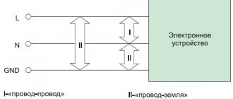
In practice, when characterizing the electromagnetic environment, the terms “electric field”, “magnetic field”, “electromagnetic field” (hereinafter referred to as EMF) are used. What does this mean and what connection exists between them?
An electric field is created by charges. For example, in all the well-known school experiments on the electrification of ebonite, an electric field is present.
A magnetic field is created when electric charges move through a conductor.
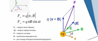
To characterize the magnitude of the electric field, the concept of electric field strength is used, symbol E, unit of measurement V/m (Volts-per-meter). The magnitude of the magnetic field is characterized by the magnetic field strength H, unit A/m (Ampere-per-meter).
By definition, an electromagnetic field is a special form of matter through which interaction occurs between electrically charged particles. The physical reasons for the existence of an electromagnetic field are related to the fact that a time-varying electric field E generates a magnetic field H, and a changing H generates a vortex electric field: both components E and H, continuously changing, excite each other. The EMF of stationary or uniformly moving charged particles is inextricably linked with these particles. With the accelerated movement of charged particles, the EMF “breaks away” from them and exists independently in the form of electromagnetic waves, without disappearing when the source is removed (for example, radio waves do not disappear even in the absence of current in the antenna that emitted them).
Electromagnetic waves are characterized by wavelength, symbolized by l (lambda). A source that generates radiation, and essentially creates electromagnetic oscillations, is characterized by a frequency, designated f.
An important feature of EMF is its division into the so-called “near” and “far” zones. In the “near” zone, or induction zone, at a distance from the source r < l, the EMF can be considered quasi-static. Here it decreases rapidly with distance, inversely proportional to the square of r -2 or the cube of r -3 of the distance. In the “near” zone, radiation from an electromagnetic wave has not yet been formed. To characterize the EMF, measurements of the alternating electric field E and the alternating magnetic field H are carried out separately. The field in the induction zone serves to form traveling field components (electromagnetic waves) responsible for radiation. The “far” zone is the zone of the formed electromagnetic wave, starting from a distance r > 3l. In the “far” zone, the field intensity decreases in inverse proportion to the distance to the source r -1.
In the “far” zone of radiation there is a connection between E and H: E = 377H, where 377 is the wave impedance of the vacuum, Ohm. Therefore, as a rule, only E is measured. In Russia, at frequencies above 300 MHz, the electromagnetic energy flux density (PED) is usually measured, which characterizes the amount of energy transferred by an electromagnetic wave per unit time through a unit surface perpendicular to the direction of propagation of the wave.
- Main sources of EMF
Among the main sources of EMR are:
- electric transport (trams, trolleybuses, trains);
- power lines (city lighting, high-voltage);
- electrical wiring (inside buildings, telecommunications);
- household electrical appliances;
- television and radio stations (broadcasting antennas);
- satellite and cellular communications (broadcasting antennas);
- radars;
- personal computers.
However, we will consider the electromagnetic safety of goods in more detail.
2.1 Household electrical appliances
All household appliances that operate using electric current are sources of electromagnetic fields. The most powerful are microwave ovens, convection ovens, refrigerators with a “no frost” system, kitchen hoods, electric stoves, and televisions. The actual EMF generated, depending on the specific model and mode of operation, can vary greatly among equipment of the same type (see Figure 1). All data below refers to a magnetic field of industrial frequency 50 Hz.
The magnetic field values are closely related to the power of the device - the higher it is, the higher the magnetic field during its operation. The values of the electric field of industrial frequency of almost all electrical household appliances do not exceed several tens of V/m at a distance of 0.5 m, which is significantly less than the maximum limit of 500 V/m.
The human body always reacts to the electromagnetic field. However, in order for this reaction to develop into pathology and lead to disease, a number of conditions must coincide, including a sufficiently high field level and duration of irradiation. Therefore, when using household appliances with low field levels and/or for a short period of time, the EMF of household appliances does not affect the health of the majority of the population. Potential danger can only be faced by people with hypersensitivity to EMFs and allergy sufferers, who also often have increased sensitivity to EMFs.
Table 1 – Magnetic field levels of industrial frequency of household electrical appliances at a distance of 0.3 m.
| Household electrical appliance | From , µT | Up to, µT |
| Iron | 0,0 | 0,4 |
| TV | 0,0 | 2,0 |
| Coffee maker | 0,0 | 0,2 |
| Washing machine | 0,0 | 0,3 |
| Vacuum cleaner | 0,2 | 2,2 |
| Electric stove | 0,4 | 4,5 |
| Mixer | 0,5 | 2,2 |
| Fluorescent Lamp | 0,5 | 2,5 |
| Drill | 2,2 | 5,4 |
| Microwave | 4,0 | 12 |
In addition, according to modern concepts, a magnetic field of industrial frequency can be dangerous to human health if prolonged exposure occurs (regularly, at least 8 hours a day, for several years) with a level above 0.2 microtesla.
You should worry about your health by following these simple rules:
- when purchasing household appliances, it is necessary to check in the Hygienic Report (certificate) the mark on the product’s compliance with the requirements of “Interstate sanitary standards for permissible levels of physical factors when using consumer goods in domestic conditions”, MSanPiN 001-96;
- you should use equipment with less power consumption: magnetic fields of industrial frequency will be less, all other things being equal;
- Potentially unfavorable sources of a magnetic field of industrial frequency in an apartment include refrigerators with a “no-frost” system, some types of “warm floors”, heaters, televisions, some alarm systems, various types of chargers, rectifiers and current converters - the sleeping place should be at a distance at least 2 meters from these objects if they work during night rest;
- when placing household appliances in an apartment: household electrical appliances are placed as far as possible from rest areas, without placing them nearby or stacking them on top of each other.
Microwave oven (or microwave oven)
In its work, it uses an electromagnetic field, also called microwave radiation or microwave radiation, to heat food. The operating frequency of microwave radiation of microwave ovens is 2.45 GHz. It is this radiation that many people fear. However, modern microwave ovens are equipped with fairly advanced protection that prevents the electromagnetic field from escaping beyond the working volume. At the same time, it cannot be said that the field does not penetrate at all outside the microwave oven. For various reasons, part of the electromagnetic field intended for the chicken penetrates outward, especially intensely, usually in the area of the lower right corner of the door. To ensure safety when using ovens at home, Russia has sanitary standards that limit the maximum leakage of microwave radiation from a microwave oven. They are called “Maximum permissible levels of energy flux density created by microwave ovens” and have the designation SN No. 2666-83. According to these sanitary standards, the energy flux density of the electromagnetic field should not exceed 10 μW/cm2 at a distance of 50 cm from any point of the stove body when heating 1 liter of water. In practice, almost all new modern microwave ovens meet this requirement with a large margin. However, when purchasing a new stove, you need to make sure that the certificate of conformity states that your stove meets the requirements of these sanitary standards.
It must be remembered that over time the degree of protection may decrease, mainly due to the appearance of microcracks in the door seal. This can happen both due to dirt and mechanical damage. Therefore, the door and its seal require careful handling and careful maintenance. The guaranteed durability of protection against electromagnetic field leaks during normal operation is several years. After 5-6 years of operation, it is advisable to check the quality of protection and invite a specialist from a specially accredited laboratory for monitoring electromagnetic fields.
In addition to microwave radiation, the operation of a microwave oven is accompanied by an intense magnetic field created by an industrial frequency current of 50 Hz flowing in the oven's power supply system. For the population, the level of the industrial frequency magnetic field in our country is still not limited, despite its significant effect on the human body during prolonged exposure. In domestic conditions, a single short-term switching on (for a few minutes) will not have a significant impact on human health. However, now a household microwave oven is often used to heat food in cafes and in similar other industrial settings. In this case, a person working with it finds himself in a situation of chronic exposure to a magnetic field of industrial frequency. In this case, mandatory control of the industrial frequency magnetic field and microwave radiation is necessary at the workplace. Considering the specifics of the microwave oven, it is advisable to move away from a distance of at least 1.5 meters after turning it on - in this case, the electromagnetic field is guaranteed not to affect you at all.
2.2 Cellular
Cellular radiotelephony is one of the most rapidly developing telecommunication systems today. Currently, around the world there are more than 85 million subscribers using the services of this type of mobile (mobile) communications (in Russia - more than 600 thousand). It is expected that by 2001 their number will increase to 200–210 million (in Russia - about 1 million).
The main elements of a cellular communication system are base stations (BS) and mobile radiotelephones (MRT). Base stations maintain radio communication with mobile radiotelephones, as a result of which BS and MRI are sources of electromagnetic radiation in the UHF range. An important feature of the cellular radio communication system is the very efficient use of the radio frequency spectrum allocated for the system’s operation (repeated use of the same frequencies, use of different access methods), which makes it possible to provide telephone communications to a significant number of subscribers. The system uses the principle of dividing a certain territory into zones, or “cells,” with a radius of usually 0.5–10 kilometers.
Different types of electromagnetic waves
A spherical wave is a wave for which the surfaces of equal phases (equiphase surfaces) are the surfaces of concentric spheres, the center of which is aligned with the radiation source. A spherical wave is one of the solutions to the wave equation (however, it is not a solution to Maxwell's equation). This follows from the fact that it is impossible to physically realize a source that would radiate energy with the same intensity in all directions. Note that such a source emitting a spherical wave is called isotropic (Figure 2.5a).
The introduction of the concept of a spherical wave source is very useful. For example, using it, you can quite simply explain Huygens' principle, according to which every point in space in which an electromagnetic field exists is a source of a spherical wave. At a sufficiently large distance from the source, the surface sector of a spherical wave can be considered as a plane wave.
A plane wave is a wave for which the equiphase surfaces are planes.
An arbitrary wave, for example a plane one, falling on a screen with a small hole (Fig. 2.5b), creates a secondary spherical wave behind it (Huygens' principle). The change in waveform is an irreversible process in this case.
A slightly different situation arises when a plane wave is incident on a screen with an extended hole (Fig. 2.5c). In this case, a cylindrical wave appears behind the screen. The process of transformation of one type of wave into another is irreversible in this case.
The above qualitative analysis of the conversion of one wave type to another can be very useful when studying certain types of antennas.
ELECTROMAGNETIC INFLUENCE
Many diseases arise precisely due to exposure to electromagnetic radiation. EMF is a real invisible danger to us.
We have become accustomed to the benefits of civilization and are now unlikely to give up computers, mobile phones, microwave ovens and everything that can be plugged into an outlet. Meanwhile, all these devices create electromagnetic fields (EMFs) that are negative for human health, which we cannot see, and therefore do not pay attention to them.
According to statistics, more than 50% of diseases can be avoided if exposure to electromagnetic radiation is minimized! Measuring electromagnetic radiation will change the situation for the better!
Are you sure that electromagnetic radiation in your apartment is normal and does not affect you?
Perhaps you only use the refrigerator among electrical appliances and never turn on the washing machine, hair dryer, router and TV. But your neighbors are sure to use these and other amenities, spreading and increasing their exposure to electromagnetic radiation. Do not forget that around our houses there are also tram and trolleybus networks, power lines and transformer boxes, which are also sources of electromagnetic fields.
Free consultation from a TESTECO laboratory specialist
We will answer all your questions:
- How to check electromagnetic fields indoors
- What could be the source of EMF
- How to protect yourself from radiation
- The effect of radiation on the human body
- How does power line affect
- Safe distance from power lines
Measurement of electromagnetic fields in accordance with the most stringent standards of the Russian Federation. Laboratory TestEco. 24/7/7 days a week
+7 (499) 322-74-23 +7 (812)317-78-83
How do you feel at work, surrounded by computers, coffee makers and production equipment?
- In America, Europe and self-respecting Russian organizations, they take care of their employees and install protective equipment against the effects of electromagnetic radiation.
- The level of efficiency of specialists in these companies doubles.
How to protect yourself from EMF exposure while continuing to use modern technology?
- Call our TextEco Laboratory and get advice from our specialists.
- Order an EMF level measurement in your home or office.
- Reduce the negative impact of electromagnetic fields to normal levels with the help of our recommendations and modern devices.
+7 (499) 322-74-23 +7 (812)317-78-83
Attention! Do not use an unaccredited laboratory. Accreditation of a testing laboratory is confirmation of the laboratory’s competence in the declared areas of activity.
Accreditation is a necessary condition for the activities of testing laboratories.
How to check a laboratory
QUESTION ANSWER
How do electromagnetic fields affect humans?
The electromagnetic field has a negative effect on the human body. A large number of studies conducted in Russia have shown that it is the nervous system that is most sensitive to the effects of EMFs. Immunity is reduced under the influence of electromagnetic fields. A change in protein metabolism may occur, and a certain change in blood composition is observed.
What are the sources of electromagnetic fields?
Factors of electromagnetic nature that are potentially dangerous to human health include constant electric and magnetic fields, alternating electromagnetic fields in the frequency range from 1 Hz to 300 GHz, in which EMF frequencies of 50 Hz (EMF IF) are especially distinguished.
Some sources of danger:
- unbalanced currents in the layouts of three phase cable lines, busbars, trays of the 0.4 kV power supply system;
- power equipment built into the building: TP, RTP, main switchboard, etc., including house and floor power supply panels;
- currents flowing through communications, pipes and metal structures of the building, wires of overhead power lines;
- currents from pipeline cathodic protection stations;
- equalizing currents flowing through earth buses;
- a room into which voltages of single-phase lines of different phases are introduced;
- electrical appliances powered from adapters containing transformers with undivided windings (or transformerless), located closer than 0.5 m from the human body;
- household electrical appliances such as refrigerators, washing machines, etc., used without protective grounding;
- lighting sources whose switch is connected to the neutral wire, and not to the phase wire, etc.
How to reduce electromagnetic influence?
To protect the population in the Russian Federation, there is a sanitary and hygienic standardization of electromagnetic fields, based on many years of research and determination of their impact on the human body.
There must be a sanitary protection zone around the sources of the electromagnetic field; if necessary, measures must be taken to reduce the electric field strength in residential buildings and in places where people may stay for a long time by using protective screens. The size of this zone is determined by law depending on the type of source. Within the sanitary protection zone it is prohibited: to place residential and public buildings and structures; summer cottages and garden plots; arrange parking areas for all types of transport; locate automobile service businesses.
Electromagnetic fields in the apartment.
In our houses and apartments there are practically no household appliances around which a magnetic field would not form. The most dangerous in this sense are microwave ovens and electric stoves. Further in descending order: TV, fluorescent lamp, vacuum cleaner, heated floors, mixer, washing machine, iron, coffee maker.
Risk areas for some household appliances:
- Refrigerator – 1.2-1.5 m;
- TV – 1.1-1.2 m;
- Electric oven – 0.4 m;
- Electric heater – 0.3 m;
- Iron – 0.23 m;
Of course, there is no need to give up household appliances, you just need to place them correctly and start from the very beginning - check the serviceability of the wiring.
When planning the interior, it is necessary to take into account that magnetic fields are not extinguished and freely penetrate into the apartment not only through interior partitions, but also through load-bearing walls. Therefore, before installing a bed or sofa against a wall, it is worth checking whether there are sources of electromagnetic fields behind this wall.
Components of the field and energy of an electromagnetic wave.
The properties of an electromagnetic wave are entirely described by Maxwell's equations. These equations allow, in principle, with an arbitrary current distribution in the antenna, to determine the nature of the electromagnetic field in the near and far zones and thereby predict the signal strength in the receiving antenna. These equations are considered in the literature [1–5].
Elementary electric dipole
The simplest antenna that satisfies Maxwell's equations is an elementary electric dipole, also called a Hertz dipole. It represents two electric charges +q and –q, located at a short distance from each other (Fig. 2.6a). Such a dipole can be considered as an equivalent of the electric current element I=iωq. The physical model of an elementary electric dipole can be represented in the form of two conductor segments, to the middle of which power is applied, and the length of which is much less than the wavelength ($l\ll\lambda$), and the ends of the conductors are loaded with large capacitances (Fig. 2.6b). The current flowing in such an antenna has the same density at all its points. The dipole moment of such an emitter $$\begin{equation} p=ql=\frac{Il}{i\omega} \end{equation}\tag{2.16a}$$
has only one component, oriented along the Z axis (Fig. 2.5c).
If we use formulas to determine the strengths of the electric and magnetic fields, resulting from Maxwell’s equations and corresponding to the external source of electric current under consideration, then we can show that the components of the desired vectors E and H in the spherical coordinate system are expressed by the following formulas: $$\begin{equation} E_r =\frac{2Il}{4\pi}\frac{k^3}{\omega\varepsilon}\left[\frac{1}{\left(kr\right)^2}-\frac{i}{ \left(kr\right)^3}\right]e^{-ikr}\cos\theta \end{equation}\tag{2.17a}$$ $$\begin{equation} E_{\theta}=\ frac{Il}{4\pi}\frac{k^3}{\omega\varepsilon}\left[\frac{i}{kr}+\frac{1}{\left(kr\right)^2} -\frac{i}{\left(kr\right)^3}\right]e^{-ikr}\sin\theta \end{equation}\tag{2.17b}$$ $$\begin{equation} H_{\varphi}=\frac{Il}{4\pi}k^2\left[\frac{i}{kr}+\frac{1}{\left(kr\right)^2}\right] e^{-ikr}\sin\theta \end{equation}\tag{2.17в}$$ $$\begin{equation} E_{\varphi}=H_r=H_{\theta}=0 \end{equation} \tag{2.17y}$$
In the above expressions, the factor e-ikr determines the phase change of the field component along the direction r, and the factor cos θ or sin θ is the amplitude change in the field when the polar angle θ, measured from the Z axis, changes (Fig. 2.6c). The absence of dependences on the azimuthal angle φ in the given formulas means that these components have circular symmetry relative to the Z axis.
The given formulas make it possible to determine the components E n H of the dipole field for any distance r from the source. Let us now consider how these formulas change when the observation point moves, more precisely when the value of kr changes.
If the observation point is at such a distance from the dipole at which the relation $kr\ll{1}$ is valid, then the terms that take into account only the change in the factors (kr)-3 in the formulas ( 2.17a, b) and the factor (kr)-2 in formula (2.17c). Under these conditions that determine the near radiation zone, we can neglect the change in the phase factor e-ikr and write: $$\begin{equation} E_r=-i\left(\frac{Il}{2\pi\varepsilon{r^3} }\right)\cos\theta \end{equation}\tag{2.18a}$$ $$\begin{equation} E_{\theta}=-i\left(\frac{Il}{2\pi\varepsilon {r^3}}\right)\sin\theta \end{equation}\tag{2.18b}$$ $$\begin{equation} H_{\varphi}=\left(\frac{Il}{4\ pi{r^2}}\right)\sin\theta \end{equation}\tag{2.18в}$$
The remaining components of the vectors E and H, as before, are equal to zero.
The above formulas make it possible to identify the following properties of dipole radiation fields in the near zone:
1. The amplitude of the electric field strength created by an elementary electric dipole is equal to the amplitude of the electric field strength created by a statistical dipole formed by two charges +q and -q, separated by a distance l along the Z axis and located in a medium with dielectric constant ε.
2. The amplitude of the magnetic field strength created by an elementary electric dipole is equal to the amplitude of the magnetic field strength created by a direct current flowing in a conductor of length l (i.e., the same length as that of an elementary dipole), having the same amplitude as and current in an elementary dipole.
3. Between vectors E and H there is a phase shift close to 90°.
The near radiation zone of an elementary dipole is often called the induction zone. An example of a near zone is the space delimiting the active element of a “wave channel” antenna.
The dipole radiation zone, characterized by the distance kr=1, is called the middle zone, or Fresnel diffraction zone. For this zone, any term in formulas (2.17) cannot be neglected.
The radiation zone, characterized by a distance r for which the condition $kr\gg{1}$ is valid, is called the far zone. Under the accepted condition, we can again simplify formulas (2.17), leaving in them only terms proportional to (kr)-1. As a result, we get: $$\begin{equation} E_{\theta}=i\frac{Il}{4\pi}\frac{\omega\mu}{r}{e^{-ikr}}\sin\ theta \end{equation}$$ $$\begin{equation} H_{\varphi}=i\frac{Il}{4\pi}\frac{\omega\sqrt{\mu\varepsilon}}{r}{ e^{-ikr}}\sin\theta \end{equation}\tag{2.19}$$
The remaining components of the dipole field in the far zone are equal to zero, i.e. Er = Eφ = Hr = Hϴ = 0.
Considering the relationship given by the formula ωμ = 240π2/λ, we can write: $$\begin{equation} E_{\theta}=i\frac{60\pi{Il}}{\lambda{r}}{e^{- ikr}}\sin\theta \end{equation}\tag{2.19a}$$
Analysis of the structure of fields in the far zone of radiation shows the following.
1. The field strength is inversely proportional to the distance r from the source to the observation point.
2. The electric and magnetic field strength vectors are mutually perpendicular and perpendicular to the direction of wave propagation.
3. Radiation field strengths depend on frequency, dipole length, current amplitude and parameters of the propagation medium.
4. There is a relationship between the amplitudes E and H: $$\begin{equation} E_{\theta}=H_{\varphi}\sqrt{\frac{\mu}{\varepsilon}}=RH_{\varphi} \end {equation}\tag{2.20}$$ where R is the characteristic impedance of the medium. For free space, the characteristic impedance $$\begin{equation} R_0=\sqrt{\frac{\mu_0}{\varepsilon_0}}=120\pi=376.7 Ohm \end{equation}\tag{2.21}$$
Elementary magnetic dipole
Considering an elementary magnetic dipole instead of an elementary electric dipole, we can obtain similar formulas (2.16) for determining the structure of the emitted electromagnetic field. A physical analogue of an elementary magnetic dipole is a loop vibrator (current loop), the perimeter of which is significantly smaller than the wavelength (Fig. 2.7).
Similar to the electric moment re, which we considered in the analysis of an elementary electric dipole, we introduce the concept of a magnetic moment m, depending on the current I, the loop area s and the magnetic permeability of the medium μ: $$\begin{equation} m=\mu{Is} \end{ equation}\tag{2.22}$$
In accordance with the principle of duality, known from the theory of electrodynamics, formulas (2.16) - (2.20), obtained to describe the structure of the field of an elementary electric dipole, are also suitable for describing the structure of the radiation field of an elementary magnetic dipole. To do this, it is necessary to write t in the formulas instead of pe, and swap E and H. This procedure is described in more detail in [1, 6–8].
In practice, loop or loop antennas, the side of which is significantly shorter than the wavelength, can be used as magnetic dipoles. Slot antennas cut into an infinite screen and excited by an external alternating electric field also have identical radiation characteristics.
An electric dipole creates a so-called E-wave, which is characterized by Er≠0 and Hr=0. The magnetic dipole creates an H wave, which is characterized by the conditions: Er=0, and Нr≠0. The above is true for the near and Fresnel radiation zones. For the far zone of radiation, where Hr=Er=0 for both dipoles, the structure of the radiated field is described by a T-wave.
In order to move from particular hypothetical cases, which include elementary electric and magnetic dipoles, to a more general case, we introduce the concept of an elementary radiation surface s (aperture), the linear dimensions of which are significantly less than the wavelength (Fig. 2.8). The excitation field of an elementary surface s is specified by the vectors Ex and Нy. In the case of free space, i.e. if the relation Ex = 120πНy is valid for Ex and Hy, the radiation field of an elementary surface in the far zone of radiation is determined by the formulas $$\begin{equation} E_{\varphi}=iE_x\left(1+ \cos\theta\right)\sin\varphi\frac{s}{\lambda{r}}e^{-ikr} \end{equation}$$ $$\begin{equation} E_{\theta}=- iE_x\left(1+\cos\theta\right)\cos\varphi\frac{s}{\lambda{r}}e^{-ikr} \end{equation}\tag{2.23}$$
These relationships will be required in the future when analyzing and designing specific aperture-type antennas.
Electromagnetic field energy
The energy of a propagating electromagnetic wave does not depend on the method of excitation of the wave, but is determined only by the intensities E and H at the observation point O(r, θ, φ). In accordance with the laws of electrodynamics, the characteristic proportional to the power of the propagating wave is the Umov-Poynting vector $$\begin{equation} P=EH \end{equation}\tag{2.24}$$
The Umov-Poynting vector characterizes the flow of electromagnetic energy passing through a unit surface per unit time. Since both field E and field H change in time according to a sinusoidal law and have the same oscillation phase, the amplitude of vector P will be determined by simply multiplying the amplitudes of vectors E and H (Fig. 2.9). Taking into account formula (2.20), we obtain $$\begin{equation} P=\left(\frac{E_{\theta}^2}{R}\right)\sin^2{kr} \end{equation} \tag{2.25}$$
If we place an isotropic emitter N with radiation power P0 at the center of the sphere (Fig. 2.10), then for an arbitrary point O(r, θ, φ) lying on the surface of the sphere, we find that the power flux density passing through this point is $$ \begin{equation} p_i=\frac{P_0}{4\pi{r^2}} \end{equation}\tag{2.26}$$
It follows that the power flux density passing through the observation point is inversely proportional to the square of the distance from the observation point to the source.
It should be remembered that an isotropic source is a hypothetical source for which, as this analysis shows, the power flux density does not depend on the spherical coordinates of the observation point. In fact, the distribution of the electromagnetic field power radiated by the antenna is not uniform, and the actual value of p may be less than, equal to, or greater than pi. The real value of p should be determined using formula (2.24), substituting into it the true values of E and H, which depend on the coordinates of the observation point O(r, φ, θ). So, for example, for elementary dipoles the values of E and H are determined by formulas (2.19), and for complex antennas - by the formulas given in § 2.3.
From the previously given formula (2.24) it follows that to determine P it is necessary to know both E and H. However, in practice it is enough to limit ourselves to knowing only one quantity (either E or H), and find the second using formula (2.20).
It is enough to simply obtain a formula relating the radiation power of an isotropic source Р0 with the effective value of the electric field strength Ed excited by the source at a distance r: $$\begin{equation} E_д=\frac{\sqrt{30P_0}}{r} \end{equation} \tag{2.27a}$$ (where Ed is given in volts per meter), or $$\begin{equation} E_d=\frac{175\sqrt{P_0}}{r} \end{equation}\tag{2.27 b}$$ where Ed is given in millivolts per meter, P0 is in kilowatts, and r is in kilometers.
The amplitude of the intensity of this field is $$\begin{equation} E=\frac{\sqrt{60P_0}}{r} \end{equation}\tag{2.27v}$$ where E has the dimension of volts per meter.
For an elementary dipole (see Fig. 2.6) radiation power $$\begin{equation} P_{emission}=80\pi^2\left(\frac{l}{\lambda}\right)^2I^2=R_ {izl}I^2 \end{equation}\tag{2.28}$$ where Rizl=80π2(l/λ)2 is the radiation resistance of the dipole.
In practice, any antenna, including an electric dipole, does not have uniform radiation. At the observation point O(r, φ, θ), the power density of the electromagnetic wave p will differ from the similar characteristic pi corresponding to a hypothetical isotropic source. Let's consider the ratio of these quantities, i.e. $$\begin{equation} D=\frac{p}{p_i} \end{equation}\tag{2.29}$$
called the antenna directivity coefficient (relative to the isotropic radiator). The directional coefficient D introduced in this way is always used to calculate the characteristics of radio communication lines. The directivity coefficient of real antennas will be calculated below.
For a receiving antenna, an important parameter is the effective value of Ed. This parameter can be easily determined by the formula $$\begin{equation} E_д=\sqrt{D}E_t \end{equation}\tag{2.30}$$ where D is the antenna directivity coefficient; Et is the field strength created by an isotropic source with power P.
Main sources of EMF
- Electric transport (trams, trolleybuses, trains,...)
- Power lines (city lighting, high voltage,...)
- Electrical wiring (inside buildings, telecommunications,…)
- Household electrical appliances
- TV and radio stations (broadcasting antennas)
- Satellite and cellular communications (broadcast antennas)
- Radars
- Personal computers
Electric
transport Electric transport - electric trains (including subway trains), trolleybuses, trams, etc. - is a relatively powerful source of magnetic field in the frequency range from 0 to 1000 Hz. According to (Stenzel et al., 1996), the maximum values of the magnetic induction flux density B in commuter trains reach 75 μT with an average value of 20 μT. The average value of V for vehicles with a DC electric drive was recorded at 29 µT. A typical result of long-term measurements of the levels of the magnetic field generated by railway transport at a distance of 12 m from the track is shown in the figure.
Power lines
The wires of a working power line create electric and magnetic fields of industrial frequency in the adjacent space. The distance over which these fields extend from the line wires reaches tens of meters. The range of propagation of the electric field depends on the voltage class of the power line (the number indicating the voltage class is in the name of the power line - for example, a 220 kV power line), the higher the voltage, the larger the zone of increased electric field level, while the size of the zone does not change during the operation of the power line.
The range of propagation of the magnetic field depends on the magnitude of the current flowing or on the line load. Since the load on power lines can change repeatedly both during the day and with changing seasons, the size of the zone of increased magnetic field level also changes.
Biological action
Electric and magnetic fields are very strong factors influencing the state of all biological objects falling within the zone of their influence. For example, in the area of influence of the electric field of power lines, insects exhibit changes in behavior: for example, bees show increased aggressiveness, anxiety, decreased performance and productivity, and a tendency to lose queens; Beetles, mosquitoes, butterflies and other flying insects exhibit changes in behavioral responses, including a change in the direction of movement towards a lower field level.
Developmental anomalies are common in plants—the shapes and sizes of flowers, leaves, and stems often change, and extra petals appear. A healthy person suffers from a relatively long stay in the field of power lines. Short-term exposure (minutes) can lead to a negative reaction only in hypersensitive people or in patients with certain types of allergies. For example, the work of English scientists in the early 90s is well known, showing that a number of allergy sufferers, when exposed to the power line field, develop an epileptic-type reaction. With prolonged stay (months - years) of people in the electromagnetic field of power lines, diseases can develop, mainly of the cardiovascular and nervous systems of the human body. In recent years, cancer has often been cited as a long-term consequence.
Sanitary standards
Studies of the biological effect of EMF IF, carried out in the USSR in the 60-70s, were focused mainly on the effect of the electrical component, since no significant biological effect of the magnetic component was experimentally discovered at typical levels. In the 70s, strict standards were introduced for the population according to EP, which are still among the most stringent in the world. They are set out in the Sanitary Standards and Rules “Protection of the population from the effects of the electric field created by overhead power lines of alternating current of industrial frequency” No. 2971-84. In accordance with these standards, all power supply facilities are designed and built.
Despite the fact that the magnetic field throughout the world is now considered the most dangerous to health, the maximum permissible magnetic field value for the population in Russia is not standardized. The reason is there is no money for research and development of standards. Most power lines were built without taking this danger into account.
Based on mass epidemiological surveys of the population living in conditions of irradiation by magnetic fields of power lines, a magnetic flux density of 0.2 - 0.3 µT.
Principles for ensuring public safety
The basic principle of protecting public health from the electromagnetic field of power lines is to establish sanitary protection zones for power lines and reduce the electric field strength in residential buildings and in places where people can stay for a long time by using protective screens.
The boundaries of sanitary protection zones for power transmission lines on existing lines are determined by the criterion of electric field strength - 1 kV/m.
Boundaries of sanitary protection zones for power lines according to SN No. 2971-84
Power line voltage
| 330 kV | 500 kV | 750 kV | 1150 kV | |
| Size of sanitary protection (security) zone | 20 m | 30 m | 40 m | 55 m |
The placement of ultra-high voltage overhead lines (750 and 1150 kV) is subject to additional requirements regarding the conditions of exposure to the electric field on the population. Thus, the closest distance from the axis of the designed 750 and 1150 kV overhead lines to the boundaries of populated areas should, as a rule, be at least 250 and 300 m, respectively.
How to determine the voltage class of power lines? It is best to contact your local power company, but you can try visually, although it is difficult for a non-specialist: 330 kV - 2 wires, 500 kV - 3 wires, 750 kV - 4 wires. Below 330 kV, one wire per phase, can only be determined approximately by the number of insulators in the garland: 220 kV 10 -15 pcs., 110 kV 6-8 pcs., 35 kV 3-5 pcs., 10 kV and below - 1 pc. .
Permissible levels of exposure to the electric field of power lines
| MPL, kV/m | Irradiation conditions |
| 0,5 | inside residential buildings |
| 1,0 | on the territory of a residential development zone |
| 5,0 | in populated areas outside of residential areas; (land of cities within the city limits within the boundaries of their long-term development for 10 years, suburban and green areas, resorts, lands of urban-type settlements within the village limits and rural settlements within the boundaries of these points) as well as in the territory of vegetable gardens and orchards; |
| 10,0 | at the intersections of overhead power lines with highways of categories 1–IV; |
| 15,0 | in uninhabited areas (undeveloped areas, even if frequently visited by people, accessible to transport, and agricultural land); |
| 20,0 | in hard-to-reach areas (inaccessible to transport and agricultural vehicles) and in areas specially fenced off to exclude public access. |
Within the sanitary protection zone of overhead lines it is prohibited:
- place residential and public buildings and structures;
- arrange parking areas for all types of transport;
- locate automobile servicing enterprises and oil and petroleum products warehouses;
- carry out operations with fuel, repair machines and mechanisms.
The territories of sanitary protection zones are allowed to be used as agricultural land, but it is recommended to grow crops on them that do not require manual labor.
If in some areas the electric field strength outside the sanitary protection zone is higher than the maximum permissible 0.5 kV/m inside the building and higher than 1 kV/m in the residential area (in places where people may be present), they must measures should be taken to reduce tensions. To do this, almost any metal mesh, grounded at at least two points, is placed on the roof of a building with a non-metal roof. In buildings with a metal roof, it is sufficient to ground the roof at at least two points. In personal plots or other places where people are located, the power frequency field strength can be reduced by installing protective screens, for example, reinforced concrete, metal fences, cable screens, trees or shrubs at least 2 m high.