Types of Electromagnetic Interference
To understand the principles of shielding, it is necessary to first understand the principles of the transmission of electromagnetic interference through connections, since shielding designed for some types of connections may be completely ineffective for others. Moreover, incorrect connection (grounding) of the shield can lead to even worse results than the absence of shielding itself. Four types of interference in circuits can degrade signal quality:
- capacitive interference;
- inductive (magnetic) interference;
- internal interference;
- radiative interference.
Capacitive interference
usually cause the least problems and are the easiest to suppress. However, they can cause distortion of high-frequency signals in conductors with high output impedance. Characteristics: high-frequency voltage fluctuations not associated with current changes. They can be seen on an oscilloscope with ordinary grounding. From a mathematical perspective, this interference can be separated from radiated interference. Suppression methods: use cables with grounded shielding. Grounding is especially important because the cable is in capacitive coupling to the shield.
Inductive (magnetic) interference
arise as a result of exposure to a strong magnetic field, operating on the principle of a generator. This can cause current to flow through a relatively low impedance conductor and disrupt signal transmission. This type of electromagnetic interference and the resulting reactions in the system can be powerful enough to turn devices on or off. Characteristics: Inductive (magnetic) interference has no DC component, frequencies can vary from the lowest to the highest within the measurement range (> 500 MHz). From a mathematical point of view, inductive interference is described in the same way as capacitive interference. Suppression methods: As a rule, a twisted pair cable with a grounded shielding braid is effective. This type of shielding suppresses interference from sources and receivers, reducing both emission and absorption of inductive noise due to the close proximity of the conductors to the grounded braid. Inductive noise will follow the path of least inductive reactance so that the braid will absorb it before it can reach the cables. Foil shielding is not as effective due to magnetic eddy currents.
Internal interference
— interference that occurs when a noise source is directly connected to the system, for example, when the power source creates impulse noise on the AC line. Characteristics: internal noise may have a non-zero DC component. DC shift is one of the characteristics of the connection type. The interference may be low frequency (eg 50 Hz noise) and will not be described by impedance laws (other than power limitations). Suppression Methods: Internal noise must be eliminated using isolation, filtering, or other impedance matching techniques. Shielding is ineffective at suppressing, but will at least help prevent interference from leaving the system. Strong internal impulse noise in an unshielded system can become inductive.
Mechanisms of penetration of pulsed interference
The inductive coupling mechanism is the main and most common physical process of the occurrence of pulsed noise.
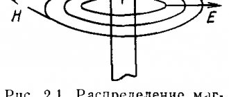
Whenever an electric current passes through a conductive material, a magnetic field is created in the environment. If a second conductor is placed in this magnetic field, and the field itself is not stationary, then a current will be induced in the second conductor. This inductive coupling may be caused by a line inducing voltage on a nearby power or data line, or the lines may also interfere with each other. Lightning can cause a much stronger impact, since a lightning discharge produces electromagnetic fields on the ground that induce energy in the conductors of various electronic circuits in much the same way that a magnetic field from one conductor can induce impulse noise in an adjacent conductor with virtually no direct contact. with this line. This type of exposure in power lines causes various undesirable effects, such as:
- Destruction. This category includes all cases where high-energy transients cause immediate equipment failure. This is often visible physical damage, such as burnt or cracked circuit boards and components, and other obvious signs.
- Damage. They usually occur when pulsed noise enters equipment through inductive interaction. The electronic components then attempt to process the pulse noise as a valid logical command. As a result, the system becomes blocked, crashes occur, erroneous data is output, and files are lost or damaged.
- Scattering. These energy impacts are associated with repetitive stress on integrated circuit (IC) components. The materials used to make ICs can withstand a certain number of repeated energy bursts, but not for a significant period of time. The ongoing accumulation of thermal energy in the components and the resulting degradation of parameters will ultimately lead to failure of electronic equipment (EE). Therefore, to ensure reliable operation of the equipment, in accordance with the scope of its application, there are test standards necessary to ensure the resistance of the equipment to impulse noise.
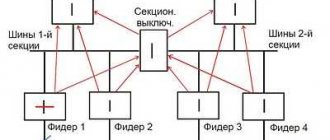
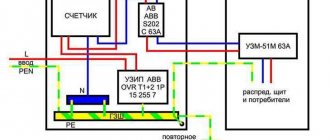
- Pulse interference. Based on the IEC 50-161-90 standard, this is electromagnetic interference, which manifests itself in the path of a specific technical device (TS) as a sequence of individual pulses or transient processes. Microsecond impulse noise (MPI) is impulse noise with a total duration of 1 μs to 1 ms. In accordance with GOST R 51317.4.5-99 [1], the causes of microsecond interference are various switching processes occurring in high and low power power supply systems, as well as various electrical atmospheric phenomena. According to this standard, impulse noise can penetrate into power ports conductively (directly through the wires) through the following circuits: “wire-to-wire” (I), “wire-to-ground” (II) (Fig. 1).
MIPs that occur at the power supply ports of the device in a wire-to-wire (I) pattern are the most dangerous due to the higher energy value carried by the interference pulse (test pulse supplied in a wire-to-wire (I) pattern with an amplitude of 1 kV , which corresponds to degree of hardness 2, has an energy of 25 J, and the MIP supplied via the wire-to-ground circuit (II) is 5 J). Therefore, the pulsed noise energy entering the electronic device through the wire-to-ground circuit (II) is less important than the wire-to-wire circuit (I) due to the different impedance of these circuits.
Rice. 1. Paths of penetration of conducted interference
In these studies, the MIP parameters and the shape of the test pulse (Fig. 2), regulated by [1], were taken as the MIPs entering the electronic device.
Rice. 2. Typical shape of a microsecond interference test pulse: pulse rise time T1 = 1 μs; pulse duration T2 = 50 μs (at 50% of the amplitude); pulse repetition period - 1 minute; output resistance of the test generator - 10 Ohms (wire-to-ground circuit); output resistance of the test generator - 2 Ohms (wire-to-wire circuit)
Modern industry produces specialized devices called surge protection devices (SPDs), which are designed to protect electronic equipment from the unwanted effects of surge noise.
At the moment, there are a number of basic approaches to creating surge protection devices, namely: SPDs either absorb energy or discharge it into the protective grounding circuit, or a combination of approaches is used, thereby providing a higher level of EA resistance.
As a rule, the process of shunting a noise pulse to grounding is implemented using various types of nonlinear components, the main operating principle of which is to reduce the ohmic resistance when the applied voltage exceeds the response level (gas dischargers, varistors, TVS diodes, TVS thyristors).
The most common and cheapest element of protection against impulse noise of this type are metal oxide varistors (MOVs), which have a pronounced nonlinear current-voltage characteristic and are capable of reducing their own active resistance when the operating voltage is reached and, accordingly, shunting the protected object.
The MOV will remain in a high-resistance state, allowing energy to flow as usual, until a voltage greater than the MOV's trigger voltage is applied to the line. As a result, the current sharply increases (from a few milliamps to hundreds of amperes) flowing through the varistor, thereby protecting the electronic components of the device from overvoltage. In this case, the voltage supplied to the equipment will be maintained at an acceptable level until the interference ends.
MOVs are often combined with fusible links (FUs) that are placed along the power path of the protected equipment (Figure 3) to interrupt the circuit if the current level exceeds what the varistor can withstand. In this case, the heating will burn out the fuse-link, which is usually located next to or attached to the MOV. As a result, the electrical circuit will be open and further supply of energy to the protected equipment will become impossible.
Rice. 3. Typical varistor connection circuit
The traditional scheme of protection against impulse noise, based on the use of MOV, is the so-called “varistor triangle” circuit (Fig. 4), which is widely used in modern SPDs.
Rice. 4. SPD circuit based on a “varistor triangle”
However, such a scheme has a significant drawback, which poses a barrier to its comprehensive use as a protection device against high-voltage impulse noise, since this solution is “disposable”: after the fuse links have tripped, operator intervention is required to replace them. In addition, all semiconductor components have inertial properties. What matters is the “reaction” time, during which the protective element changes its electrical properties to timely protect the electronic device. In those cases when the duration of the interference pulse is short compared to the “reaction” time of the SPD, unhindered penetration of the interference pulse into the protected device occurs.
Additionally, varistors have a limit to the maximum amount of energy they can dissipate as heat. It should be noted that most manufacturers of protection devices indicate in the equipment documentation the value of the maximum absorbed interference energy. However, this parameter is not accurate, since it shows the total power of all varistors included in the SPD, and it can be considered an inadequate indicator of the degree of protection of the device. Since interference typically travels through a device's power supply ports in multiple directions, it is likely that at a local location in an electronic circuit, the transmitted energy will exceed the maximum energy dissipation value of the varistor located there.
In addition to varistors, there are other types of semiconductor limiters, which also have all of the above disadvantages inherent in semiconductor devices.
Table 1 compares existing types of limiters used in the field of protecting electronic devices. Table 1.
Comparison of surge protection elements
| Security element | Advantages | Flaws | Usage |
| Gas discharger | High permissible current value 2.5–150 kA. Low capacitance (no more than 2 pF). High insulation resistance (more than 1 GOhm). Low leakage current (less than 10 nA). | Relatively long response time associated with the duration of gas ionization. Dependence of gas ionization voltage on the rate of voltage rise at the terminals. | As the first stage of combined protection of power circuits from atmospheric and switching overvoltages. |
| Varistor | Short response time (10–20 ns). Wide range of operating currents and voltages (3–20 kV, 0.1 mA–90 kA). | Limited service life, directly dependent on the power and repetition rate of the overvoltage pulses. Dependence of the actuation voltage on the flowing current. | First and second stages of combined protection. Protection of power circuits and automotive electronics. Protection of electronic components of devices. |
| TVS diode | Low voltage limit levels (units of volts). Wide range of operating currents and voltages. High speed (at least 10-12 s). Small own capacity. | Low rated pulse current (up to 200 A). Relatively high cost. | For protecting components on a printed circuit board in the final stage of a combined protection system. |
| TVS thyristor | High performance (at least 10-9 s). Large control current (up to 90 mA). | Limited operating voltage range (up to 150 V). The protected device is shunted to ground after the pulse has passed. |
The conducted research revealed the possibility of creating a new principle of protection against impulse noise, the basis of which is the use of two-stage protection of converter equipment powered from an industrial network. In this case, a DC link is used as the input circuit.
In Fig. Figure 5 shows a simplified functional diagram of the proposed SPD. Such a device consists of a series-connected filter 1 (F1), a rectifier bridge, filter 2 (F2) and a protected load. Filter 1 is designed to ensure the passport operating mode of the rectifier bridge diodes, namely, to generate the required dI
/
dt
and
dU
/
dt
. Filter 2, consisting of inductor L3 and capacitors C4, C5 (with capacitor C4 being non-polar and C5 electrolytic), connected to the output of the power rectifier. This filter, in addition to providing the required voltage ripple coefficient (L3,C5), is an accumulator of “fast” pulse noise energy (L3C4).
Rice. 5. Schematic diagram of an SPD
In Fig. Figure 6 shows the equivalent circuit of the “fast” L3C4 filter, where r1
— internal resistance of the test generator simulating a microsecond voltage pulse;
Rn
is the load resistance. Such a circuit is a second-order link in which, when an external pulse is applied to the input, oscillatory processes can occur at the output. In accordance with the theory of automatic control, for such a circuit the transfer function must be analyzed for the absence of oscillatory processes.
Rice. 6. Circuit of a “fast” LC filter
The transfer function of the “fast” L3C4 filter has the form:
where ξ is the damping coefficient; T1 , T2 -
link time constants;
k
is the link transmission coefficient.
The link time constants and transfer function coefficients are calculated using the following formulas:
The criterion for analyzing the stability of a given link is that the damping coefficient must be greater than or equal to unity (ξ ≥ 1).
In Fig. Figure 7 shows a model of an SPD operating at a load of 600 W (when modeling the SPD its maximum power is assumed to be 600 W). In this model, the electrolytic capacitor C5, in addition to capacitance, also has its own resistance and inductance (the reactive parameters of the electrolytic capacitor are assumed to be averaged).
Rice. 7. SPD model in OrCAD package
Table 2 shows the parameters of the elements of the SPD equivalent circuit.
Table 2.
Parameters of SPD equivalent circuit elements
| Element designation | Purpose | Denomination |
| V1 | Sinusoidal voltage source | U = 220 V, f = 50 Hz |
| V2 | Microsecond pulse noise (MPI) generator | UA = 1 kV, T2 = 50 µs |
| D1, D2, D3, D4 | Bridge rectifier diodes | perfect |
| D5 | Auxiliary diode that prevents network energy from entering the microsecond noise generator | |
| D6 | R6D6 damping circuit diode | |
| R1 | A resistor simulating the internal resistance of a pulse noise source) regulating the type of test (“wire-to-wire” according to GOST R 51317.4.5-99) | 2 ohm |
| r3 | Internal resistance of throttle L3 | 0.1 ohm |
| r4 | Internal resistance of non-polar capacitor C4 | 0.01 Ohm |
| r5 | Internal resistance of electrolytic capacitor C5 | 0.02 Ohm |
| R6 | Resistor damping circuit R6D6 | 10 ohm |
| Rn | Active load resistance | 100 Ohm |
| L4 | Equivalent series inductance of non-polar capacitor C4 | 1 nH |
| L5 | Equivalent series inductance of electrolytic capacitor C5 | 100 µH |
| L3 | Inductance | 0.5 mH |
| C4 | Capacitance of a non-polar capacitor | 1.2 µF |
| C5 | Electrolytic capacitor capacity | 200 µF |
The parameters of the filter elements are selected in such a way that the voltage surge at the load does not exceed 500 V with a positive MIP amplitude of 1 kV (Fig. when exposed to an interference pulse at a time corresponding to the maximum instantaneous value of the supply sinusoidal voltage (in accordance with clause 8.2 of GOST [1]).
Rice. 8. Oscillograms of currents and voltages when exposed to a pulse with an amplitude of 1 kV with a phase shift of 90° relative to the sinusoidal voltage
The processes occurring in the “fast” L3C4 filter have the following sequence (Fig. 9): at the moment the pulse arrives, the inductor current begins to increase linearly, and the alternating component of the inductor current begins to flow through the capacitor (C4); at the moment of the end of the external influence (the end of the interference pulse), the current through the inductor, and therefore through the capacitor (C4), begins to decrease to its original value.
Rice. 9. Diagrams of currents and voltages in SPD elements under the influence of MIP
An electrolytic capacitor (C5) connected in parallel with a non-polar capacitor (C4) due to the presence of an equivalent series inductance ( lvn
) does not operate when exposed to pulsed noise.
After the end of the MIP, the energy accumulated in capacitor C4 is transferred to capacitor C5, which, with its time constant, is subsequently discharged into the load resistance.
NEC Standard (National Electrical Code)
The National Fire Protection Association has published the NEC (National Electrical Code) standard, which divides all cables into two groups. The group of cables for wiring in buildings includes cables used in permanent structures, where they are not subject to deformation and are usually laid in ducts behind walls or in other places inaccessible to visual inspection.
The second group includes flexible cords and cables. These cables are designed to connect electrical appliances that can move relative to each other. Their scope of application includes industrial and handling equipment, machine tools and other systems containing moving parts with electrical cables.
The integral parts of the cable - conductor, insulation, shielding and sheath - must be well manufactured to meet the stated service life under the worst-case conditions in terms of bending and deformation. However, cables of the second type are generally not recommended for use in fixed installations because they are not intended for installation in ducts or other isolated locations and have not been tested accordingly. These cables are usually in direct line of sight - a damaged cable is easy to locate and replace.
Radiated interference
- the most complex type of interference, which has a number of specific limitations associated with frequencies that are important for understanding. Characteristics: As a rule, the device should be located at a distance of 1/2 (wavelength) from the radiation source and have an “antenna” of at least /20 length. In this case, the source of interference will be located outside the device. Methods of suppression: shielding with foil is not enough. Braided shielding can be effective, although its use in the case of radiated interference has additional requirements. First, the shield must not be interrupted within the shielded circuits. Full shielding from all directions is required. At very high frequencies, small holes or traces that would normally be acceptable can contribute significantly to the impedance. Even a harmless hole through which a cable passes can become a source of radiated interference. Anyone familiar with stereo radios will know the correct shielding method and can identify circuits and capacitors that are susceptible to radiated interference.
When cables are bent or twisted, their service life is greatly reduced. If necessary, make a fastening to ensure longitudinal displacement of the cable
Means of protection against microwave radiation
The nature of the impact of microwave radiation on a person depends on the following factors:
- distance from the radiation source and its intensity;
- duration of irradiation;
- wavelength;
- type of radiation (continuous or pulsed);
- external conditions;
- state of the body.
To quantify the danger, the concept of radiation density and permissible exposure rate was introduced. In our country, this standard is taken with a tenfold “safety margin” and is equal to 10 microwatts per centimeter (10 μW/cm). This means that the power of the microwave energy flow at a human workplace should not exceed 10 μW for each centimeter of surface.
How to be? The obvious conclusion is that exposure to microwave rays should be avoided in every possible way. Reducing exposure to microwave radiation in the home is quite simple: you should limit the time of contact with household sources.
People whose professional activities involve exposure to microwave radio waves should have a completely different protection mechanism. Means of protection against microwave radiation are divided into general and individual.
The flux of emitted energy decreases in inverse proportion to the increase in the square of the distance between the emitter and the irradiated surface. Therefore, the most important collective protective measure is to increase the distance to the radiation source.
Other effective measures to protect against microwave radiation are the following:
- reduction of radiation at the source;
- changing its direction;
- reduction of exposure time;
- remote control of emitting devices;
- use of protective shielding.
Most of them are based on the basic properties of microwave radiation - reflection and absorption by the substance of the irradiated surface. Therefore, protective screens are divided into reflective and absorbent.
Reflective screens are made of sheet metal, metal mesh and metallized fabric. The arsenal of protective screens is quite diverse. These are sheet screens made of homogeneous metal and multilayer packages, including layers of insulating and absorbing materials (shungite, carbon compounds), etc.
The final link in this chain is personal protective equipment against microwave radiation. They include workwear made of metallized fabric (robes and aprons, gloves, capes with hoods and goggles built into them). The glasses are covered with a thin layer of metal that reflects radiation. They are required to be worn when exposed to radiation of 1 µW/cm.
Wearing protective clothing reduces the level of radiation exposure by 100–1000 times.
Selecting a cable type
Selecting the appropriate type of shielded cable for a specific task and frequency region is the main point in ensuring the safety of low-level signals in control circuits and accurate and reliable positioning of the servo system. In addition, shielded cables used in high-power control loops ensure that the drive system does not affect surrounding equipment. For example, a properly connected shield can prevent noise current through the ground (sometimes called common mode noise). Shielding with braid, spiral winding and foil provides the lowest impedance path for low and high frequency noise current back to the motor. The main purpose of shielding is to suppress radio emissions. Some of the noise energy that reaches the cable shield is reflected, some is redirected across the low-impedance shield, but the remainder of the noise energy penetrates the shield and distorts low-level signals in nearby circuits. The challenge is to select the most effective shielding that minimizes interference penetration. Servo motor power cables and feedback lines are susceptible to both their own radio emissions and external electromagnetic interference. In addition to noise generated by nearby equipment and servo drive system cables, the motors themselves generate the majority of the electrical noise. To minimize this, feedback loop cabling, analog, digital and other low-voltage circuits are shielded to suppress both absorbed and radiated EMI. Twisted pairs are also often shielded to reduce crosstalk. Twisting the signal and ground wires reduces radiation, and shielding the resulting twisted pair adds another layer of protection and suppresses crosstalk between external circuits and conductors in the cable. External shielding protects the circuit from external electromagnetic interference and reduces radiation from the cable itself. Servo power cables generate powerful electromagnetic radiation due to the very rapid switching on and off of motor current. Due to the sudden change in current, significant high-frequency interference of capacitive and inductive types occurs, emitted by the power cable. Shielding power cables reduces radiation levels and also protects feedback loops and system equipment. When selecting the correct shielding, there are many factors to consider, including the shielding material. Among them:
- some cables have a common shielding that contains all conductors at the same time,
- in other cables individual conductors or pairs are shielded,
- cables intended for adverse external conditions contain both individual and general shielding.
Double shielding separated by an insulator layer improves immunity to interference but reduces cable flexibility. For example, the first layer of aluminum foil shielding provides 100% coverage and protection against high-frequency interference. A second layer of copper braid (on top of the insulating layer) increases protection against low-frequency interference, significantly adds strength and increases flex life.
Recommendations for reducing electromagnetic interference in cable connections
Here are some general recommendations for increasing the servo system's immunity to electromagnetic noise:
- Cables, especially in feedback loops, should not be too short to avoid severe bends or too long, as this will lead to increased noise levels that distort the signal. If motor and drive cables are longer than necessary, they emit more noise. Cables should be kept as short as possible.
- Using separate power and feedback cables reduces crosstalk between high-current motor-to-drive lines, low-voltage feedback lines, and other analog and digital lines. Power and signal cables should be laid, if possible, in different channels or separated by at least 10 cm for currents up to 20 A, 15 cm for currents up to 40 A and 20 cm for currents up to 80 A. If power and signal cables cross , they must be positioned strictly perpendicular to each other.
- Composite cables (power/feedback) save space and simplify wiring, but significantly increase the likelihood of electromagnetic interference from the power lines affecting the feedback circuit. The signal lines of high-quality composite cables are combined into twisted pairs with double shielding.
- Many servo motor manufacturers supply pre-fabricated cables with the system. These cables save time and usually produce much better results than homemade cables.
- For cable lengths greater than 25 meters, it is recommended to use common filters on the motors.
- When AC power supply filters are used, the inputs and outputs must be located separately.
- In analog circuits, differential inputs are much less susceptible to noise than single-terminal inputs. Signals must be transmitted over shielded cables with braided wires grounded at both ends. The shields of power cables must also be grounded on the motor and drive sides to prevent interference from the motor windings from entering the circuit.
- The cable shielding at the connection points must be complete. You should not leave the “tails” of the braid for grounding, since part of the conductor remains open to electromagnetic interference. Do not separate cables in front of the terminal block. All metal parts of the housings must be connected with conductive cords. To ensure good contact, paint should be removed from the drive mounting areas on the panel.
Braid
usually consists of woven copper strands covering individual conductors, twisted pairs, or all conductors in a cable simultaneously. The coverage percentage is determined by the density of the threads in the braid and is usually 60-95%. A higher coverage percentage means better EMI protection and reduced RF emissions. The diameter of the threads, usually equal to 32 and 40 AWG (note: American Wire Gauge (AWG) is a system of wire thickness marking standards used in the USA. The lower the AWG number, the thicker the wire and the lower its resistance), the flexibility of the braiding, the life bending service and degree of coverage. Tinned filaments are more resistant to corrosion, provide better electrical contact and are easier to solder, but are not as flexible as bare filaments of the same size. Flexible servo cables are typically braided with very high quality bare strands. Signal cables must consist of twisted pairs enclosed in a foil shield in a common braid.
Spiral winding
provides greater flexibility and flex life than braid. It consists of bare or tinned wire twisted in a spiral around a conductor.
There is an optimal combination of mechanical strength and degree of cable shielding for applications
Spiral winding is best for low frequencies and often provides greater than 95% coverage. It is used in the most flexible and resistant to deformation, such as twisting, cables, where braided and especially foil shielding can be damaged when the cable is twisted. Grounding the spiral winding becomes more difficult if it is closed. A foil shield is usually made of aluminum foil on a polyester backing. The backing is necessary for mechanical strength. Aluminum provides effective protection against capacitive-type high-frequency interference. Copper wire is not used as often and covers the lower frequency range. The foil shield can be applied to the conductor in one of three ways: with the foil facing the conductor, with the foil facing out, or with the edges of the wrapped foil strip folded into a Z shape. The first two methods allow some noise leakage, since there is no direct conductive contact at the places where the foil and substrate are applied. While bending the edges in a Z shape allows for complete coverage of the conductor as the foil is in direct contact with the foil when applied. An additional wire along the foil screen ensures reliable grounding.
How to reduce electromagnetic interference in design?
Solving electromagnetic compatibility problems of electronic devices is more expensive if they arise at the manufacturing stage. Therefore, taking into account at the early stages of development all factors that can influence the appearance of EMI helps to avoid unpleasant surprises during testing of the finished device for electromagnetic compatibility.
With increasing demand for high-speed circuits, PCB design has become increasingly complex. In addition to minimizing PCB interference, engineers must consider many other factors that affect circuit performance, including power consumption, PCB size, and interference in the environment.
The following describes electronic circuit design techniques during the PCB development phase that enable devices to successfully pass EMC tests.
Grounding diagram
A low inductance ground is the most important element in minimizing EMI on a PCB. Maximizing the ground bus area on the PCB reduces the ground inductance in the system, which in turn reduces electromagnetic emissions and crosstalk.
Circuit blocks and components can be connected to ground in a variety of ways. It is bad when components are connected to ground points randomly. This approach results in high ground inductance and inevitable EMC problems in the system.
The recommended approach when designing a PCB is to use a separate layer of earth, because it provides the lowest impedance because the current then returns back to the source. However, in the case of a two-layer PCB, this approach is not possible. In this case, a grounding network should be used, as shown in Figure 1a. The ground inductance will depend on the pitch of the ground grid.
| Rice. 1. Recommended grounding methods for PCB |
The path that the signal takes back to the system ground is also quite important because when the signal takes a longer path, it creates a ground loop that forms the antenna and radiates energy. Thus, each conductor carrying current back to the source must follow the shortest path to the ground bus.
Do not connect all the individual component ground planes and then connect them to the ground plane because This not only increases the size of the current loop, but also increases the likelihood of ground noise. Figure 1c shows the recommended method for connecting components to the ground bus.
Using a Faraday shield is another good way to reduce EMF problems. The Faraday shield is formed by piercing the ground layer along the entire periphery of the printed circuit board with vias. No signals are routed outside this boundary (see Fig. 1b). This method limits the emission of interference to the PCB within the boundary indicated by the shield.
Dividing the PCB into areas
To reduce EMI, components on the PCB must be grouped according to their functional purpose, for example, analog and digital blocks, power supply section, low-speed circuits, high-speed circuits, etc. Conductors for each group of blocks must be routed within the allocated area. For a signal that is transmitted from one subsystem to another, a filter should be used at the boundaries of the subsystem.
Conductors carrying analog signals should be located away from high-speed or pulsed signals and protected by a ground bus. A low-pass filter should always be used to suppress high-frequency noise that may be coupled to analog signals. In addition, it is important that the ground buses of the analog and digital parts of the circuit are not common.
When designing a PCB topology, the various circuit blocks must be arranged in such a way that there is sufficient space around the sensitive inputs with respect to pulsed signals with high amplitude and/or frequency, because these signals may cause interference. Placing the wires in parallel on the board ensures good communication between the signals of these wires. If such a connection is not desirable, the ground buses should be located between these conductors. If these traces must cross each other in different layers, the conductors must be routed at right angles in order to minimize the coupling area. Tracks should be kept as short as possible, especially those carrying RF or pulsed signals with short edges.
PCB Layers
Proper placement of PCB layers is vital in terms of minimizing EMI. If more than two layers are used, then the entire layer must be used as a ground layer. In the case of a four-layer board, a power layer must be located under the ground layer. Figure 2a shows this type of layer arrangement.
It should be taken into account that the ground layer should always be located between the high-frequency signal conductors and the power layer. If a two-layer board is used and it is impossible to take one layer underground, then a grounding network should be used. Unless a separate power plane is used, the ground planes should be parallel to the power planes to ensure that those planes are free from interference.
It is preferable to maintain a minimum distance between the signal layer and the adjacent ground/power layer. This provides relatively low impedance even for fairly thin conductors. The appearance of cracks in the ground layer should be avoided to prevent the formation of slot antennas. In addition, it is necessary to eliminate small “islands” in the layers of the earth. Different areas of the ground must be connected using vias (for most boards, one via for every 3...5 mm of conductor is sufficient).
When developing PCBs, transitions between layers should be reduced to a minimum. Each via, especially the “long” one, i.e. the one that goes from the top layer to the bottom contains some inductance, the value of which is, as a rule, 0.5...1 nH. Particular attention should be paid to connecting the decoupling capacitor to the ground bus. It is recommended to place several vias in parallel near the corresponding capacitor.
High speed circuits
When designing digital circuits, special attention is paid to clock and other high-speed signals. Conductors carrying such signals should be kept as short as possible and placed in a layer adjacent to the ground layer to control crosstalk. Engineers should avoid using vias or placing traces carrying such signals at the edge of the PCB or near connectors. These signals should be located away from the power buses, because they also interfere with the supply voltage.
Careful consideration must be given to what clock speed is actually needed for a given application. You should choose the lowest possible operating frequency, because Electromagnetic emission primarily depends on this. When wiring the generator circuit, no buses other than ground should be located near or under the generator circuit. The quartz resonator must also be placed next to the corresponding crystal.
It should be noted that the return current always flows along the path with the least resistance. Therefore, the ground bars carrying the return current must be located close to the traces carrying the corresponding signal in order to make the current loop as short as possible.
The differential signals must be routed close together with both lines being the same length to make the most efficient use of the magnetic field cancellation capability. Large loops should be avoided and return paths should be provided. The larger the area of the loops, the greater their sensitivity and the lower the frequency that can affect the operation of the circuit. This is also true for electromagnetic field radiation—any conductors that form loops with radio frequency current can behave like antennas.
The conductors that carry clock signals from the source to the device must have a matched load because In case of impedance mismatch, part of the signal is reflected. If proper matching is not provided, most of the energy will be wasted. There are many ways to create an effective load, including source load, termination load, AC load, and others.
Crosstalk can be present between any two conductors on a PCB and depends on mutual inductance and mutual capacitance, which are determined by the distance between the two conductors, the leading edge of the pulses, and the impedance of the conductors. In digital systems, crosstalk caused by mutual induction typically exceeds crosstalk caused by mutual capacitance. Mutual inductance can be reduced by increasing the distance between the two conductors or decreasing the distance from the ground bus.
Critical circuit components, such as tuners, may require shielding. The length of critical connections should be chosen to be less than 1/10 of the wavelength for the highest frequency the circuit generates.
There are two considerations to keep in mind here. First, the wavelength (λ) on the PCB is shortened due to the influence of the relative permittivity of the board material (εr). For the FR4 material, the dielectric constant is ~4.5. However, the effective value of εr will be even smaller, because part of the electric field of the microstrip line is in free space. The wavelength is determined by the following formula:
.
For a frequency of 3 GHz, according to this formula, the length of the conductor, equal to ~50 mm, is already 1/10 of the wavelength. Secondly, the highest frequency in the circuit is determined by the shortest signal rise time, so if some components of the system operate at a frequency of 1 MHz with a rise time of 1 ns, then the PCB will contain signals with a frequency of at least 500 MHz.
Decoupling Capacitors and Resistors
Any interference on the power supply will affect the operation of the device. Typically, noise associated with the power supply is high frequency, so it is necessary to use a bypass or decoupling capacitor to filter out this noise.
The decoupling capacitor provides a low-resistance path for high-frequency current from the power rail to ground. The path that current travels towards ground forms the ground loop. The length of this path should be minimized by placing a decoupling capacitor close to the chip (see Fig. 2b). Long ground loops increase noise emissions and can act as potential sources of failure.
| Rice. 2. a) variant of the arrangement of layers in a four-layer board; b) mounting a decoupling capacitor on the board |
The reactance of an ideal capacitor tends to zero as frequency increases. However, keep in mind that at higher frequencies the capacitor also has some built-in parasitic components, such as series inductance and resistance known as equivalent series resistance (ESR). In addition, the pins and the chip body add inductance.
The simplest capacitor equivalent circuit contains a nominal capacitor, an ESR, and a parasitic series inductance. ESR determines the lowest amount of impedance that is achieved when the capacitor is in series resonance. Above this series resistance, the impedance of the capacitor will increase with frequency, i.e. the capacitor begins to behave like an inductance. A more complex capacitor model also contains a capacitor Cp and a resistor Rp (see Fig. 3).
| Rice. 3. Capacitor equivalent circuit |
The parasitic inductance together with the capacitor Cp leads to parallel resonance, which is often neglected because in conventional ceramic SMD capacitors it occurs only at frequencies exceeding several GHz.
The series resonance of a capacitor is determined by its type (electrolytic, film, ceramic), mechanical dimensions and shape, and, of course, its rating. Therefore, it is recommended not to simply place a single decoupling capacitor, but to use two or more capacitors to provide wideband decoupling. For example, a pair of 10 nF capacitor for low frequencies and a 100 pF capacitor for higher frequencies is often used.
The decoupling capacitors should be placed as close to each other and to the component as possible. In addition, it is useful to use multilayer boards with a ground layer located just below the signal layer. It is also important to simulate circuits based on the actual parameters of specific capacitors, and not just select them blindly. Some designs place only a single central group of capacitors to decouple a large area, but this should not be done without careful modeling.
In addition, resistors must be considered as more complex components (the parameters of which are highly dependent on the type of construction and the value of resistance). The resistor equivalent circuit is shown in Figure 4. Fortunately, for typical low-impedance thin-film resistors used to construct EMI filters, the contribution of parasitic elements is in most cases negligible up to 1 GHz frequencies.
| Rice. 4. Resistor equivalent circuit |
Cables and shielding
Most EMC problems are caused by cables carrying digital signals, which act as an effective antenna. It is ideal when the current entering the cable exits it at the other end without loss, but in reality the current is affected by parasitic capacitance and inductance, which emit an electromagnetic field.
Using twisted pair cable eliminates any induced magnetic fields. When flat cable is used, many wires are needed to provide multiple paths for the current to return through the ground. For high frequency signals, shielded cables should be used, in which the shield is connected to ground at the beginning and end of the cable.
Shielding is a mechanical method of reducing EMF. Metal enclosures (conductive and/or magnetic materials) are used to prevent interference from entering the system. The screen can be used to cover the entire system or part of it, depending on the requirements. The shield resembles a closed conductive container connected to ground, which effectively reduces the size of loop antennas by absorbing and reflecting some of their radiation.
In this way, the shield also acts as a divider between two regions of space, attenuating the electromagnetic energy emitted. The shield reduces EMF by weakening the electric and magnetic field of the emitted wave.
Protection of chip ports from radio frequency interference
High-impedance IC ports are susceptible to RFI, so their impedance should be reduced to an acceptable level or a low-impedance path to the RF ground bus should be provided. If it is specifically stated that certain ground pins in the chip are connected to certain supply voltage pins or ports where decoupling capacitors should be located, this should be taken into account.
Ports that are connected outside the electronic module require special attention - decoupling capacitors and series resistors should be placed on them if possible. Resistors of 10 to 100 ohms are often used, but while higher resistor values provide more efficient filters, they also cause higher voltage drops for DC signals. If emissions from a particular port are causing problems, then one end of the resistor is connected to the port and a capacitor is connected to the other side. For frequencies above 10 MHz, ferrite beads may be more effective, not just resistors.
Literature
1. Ashish Kumar, Pushek Madaan. Top 10 EMC design considerations//www2.electronicproducts.com.
2. Christoph Hammerschmidt. EMC - Synonym for Exasperating, Magic, Confusing?//www.automotivedesign-europe.com.
Requirements of UL, CSA, CE standards
In addition to reducing or eliminating interference to servo systems and surrounding equipment, shielding may be necessary to ensure compliance with certain regulatory standards, such as CE (European Union Quality and Safety Standards). The conductor diameter, insulation type and quality mark (if any) are usually marked on the cable insulation along with the voltage and temperature class. The UL and CSA marks certify that the cable has been tested by one or both organizations for safe use in accordance with the manufacturer's specifications. However, this does not mean that the cable is perfectly shielded. The CE standard sets limits for line noise levels, but simply using CE certified cable does not guarantee that the entire system is CE compliant. Compliance with the standard is also determined by how the cable is used, so careful study of the specifications and testing in a real installation is essential.
Flexibility requirements
Cables for applications where flexibility is a major factor usually have:
- high-quality conductors made of copper threads;
- flexible insulation;
- non-slip insulating components on each conductor layer;
- uniform winding of the bundle of conductors;
- the inner sheath between the bundle of conductors and the screen;
- very high quality copper braided shielding;
- a foil screen with a cord around the line for feedback;
- flexible outer shell.
Flexible cable shields are made from high-quality bare copper strands, which very easily take the form of a bundle of conductors. When the cable is bent, the shield should slide along the bundle of conductors with low friction and not get stuck on discontinuities formed by individual conductors or the spaces between them. The absence of a smooth cylindrical surface under the shield can lead to permanent deformation (twisting) of the cable. A thin inner sheath is placed between the screen and the bundle of conductors to fill the gaps between the conductors and thereby form a smooth cylindrical surface on which the screen will slide well. A good way to create a smooth surface under the screen is to add fillers and textile fiber wraps. Another feature of the cable manufacturing process is the stamped inner sheath, which, due to its structure, maintains the almost perfect cylindrical shape of the conductor bundle even during bending. This method is more expensive than the fill and winding technology, but provides greater reliability. The screen is braided or wound around the inner shell, then covered with the outer shell. The relative displacement of cable components during bending creates triboelectric noise, which results in static and piezoelectric interference. Carefully designed cables minimize this phenomenon but must always be taken into account. Different types of deformation affect the choice of cable components, including the shield. Common types of cable deformation include buckling, transverse bending and twisting. The technical specifications indicate the type of deformation that will not cause damage to the cable. Transverse bending is the bending or rotation of the free end of a cable attached to a hinge in different directions. Buckling occurs when one end of a cable is fixed and the other end is moved back and forth. Cables intended for linear bends only should not be twisted. For example, torsion occurs in robotics when the robot arm, which contains cables, rotates counterclockwise and clockwise. For such tasks, a spiral winding screen is best suited.
See also the collection “Electromagnetic compatibility in electronics”.
Facebook
Interference of transmitting devices and methods for eliminating them
Every radio amateur, to one degree or another, has to solve problems related to eliminating interference in televisions and radios, as well as in other household equipment, for example, telephones, tape recorders, etc. Finding and eliminating the cause of the interference is a very difficult matter, because the problem usually involves several factors. It is optimal, in the author’s opinion, to consider all the components of the radio station (antenna-feeder devices, grounding, etc.) - they must correspond to a high level of performance. The quality of the transceiver (transmitter) plays an important role in preventing interference with household equipment. Radio spurious interference, caused by transmitter harmonics or spurious emissions whose frequency is unrelated to the frequency of the wanted signal, is often a major problem. Good shielding of the transmitter is a necessary condition for its operation. When the transmitter meets all the standards for this type of equipment, but there is still interference, you should move on to the radio station equipment as a whole. In areas of poor television reception, resonant antennas can be recommended as antenna systems for radio stations. As a rule, this is a separate antenna for each band with a low SWR, powered by a coaxial cable. It is good practice to install transmitting antennas as far and high as possible from television antennas.
The radio station must have a calibrated SWR meter, with which you can determine the SWR values in the transmission line at any moment. Most radio amateurs in the world believe that one should not simplify the radio station by abandoning auxiliary devices.
The next step is to properly make the grounding. Considering that a radio amateur is dealing with a transmitting device, it is necessary to have RF grounding. An integral part of the radio station is a surge filter, which prevents interference from entering the electrical network, and also protects the receiving part of the station from local interference that can penetrate through the electrical network. In most cases, such interference is caused by sparks from nearby electrical appliances and electrical installations. The next stage in the radio station equipment is the manufacture of a low-pass filter (LPF), which makes it possible to further suppress the harmonics of the transmitter.
The cutoff frequency (cutoff frequency) at which the filter oscillations begin to weaken usually lies in the range of 34...40 MHz. The filter is connected to the coaxial transmission line (after the SWR meter), placed in the screen and be sure to be grounded. The input and output impedances of the filter must be matched to the characteristic impedance of the feeder line used.
Sometimes, if grounding is unsuccessful and SWR = 1, asymmetry currents occur that flow along the outer side of the cable braid, which leads to radiation of the transmission line. To eliminate this, an RF choke is used. The cable after the SWR meter and low-pass filter is made several turns on a ferrite ring with a diameter of 5...8 cm with a permeability of >100. Sometimes it is useful to turn on such a choke on the roof at the point where the cable connects to the antenna.
So, having equipped the radio station with an antenna with a minimum SWR, made a mains filter, a low-pass filter, performed RF grounding and installed an RF choke, we have done everything we could with the transmitter, and now we can look at the problem of interference from the household equipment itself.
In television receivers it is desirable (especially in 2nd generation TV) to install a simple and effective surge filter .
Line filters and high pass filters
The winding of the surge protector is carried out using a power cable on a long round ferrite rod with permeability >400. The number of turns is maximum, along the entire length of the rod. Winding - turn to turn.
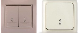
It is also recommended to use a high-pass filter (HPF) (Fig. above), which increases the selectivity of the TV and reduces the influence of the main transmitter signal and its harmonics. The filter is turned on via the antenna input of the TV, shielded and grounded. L1…L10—8 turns of bare copper wire with a diameter of 1 mm. Winding - frameless, diameter - 7 mm. Inductance - 0.18 µH. Interference suppression in the range of 3.5...21 MHz is more than 70 dB, 28 MHz is about 50 dB.
Very often the problem is resolved by using an RF choke at the antenna input of the TV. Conveniently, this does not require any intervention in the TV or soldering.
RF choke
The RF choke is made from a TV antenna cable, several (3...10) turns are made through a ring (permeability >100) with an outer diameter of about 5...8 cm. Instead of a ring, you can use a ferrite core from a failed line transformer.
In FM VHF broadcast receivers, the elimination method is similar to television. In telephones, the microphone is bypassed with a 0.01 micron ceramic capacitor, and an effective telephone filter .
In stereo equipment, eliminating interference comes down to installing a filter between the ULF output and the speaker system, as well as installing a surge protector.
Filter between ULF and mains filter (lower)
In tape recorders, the problem worsens in recording mode. To do this, the recording (universal) head is shielded, and any of the network filter circuits is used. Your computer may not function properly if it is located near a powerful transmitter. At the same time, the computer is a source of interference to broadcast receivers, especially the VHF range. While not excluding direct exposure to RF radiation through the plastic computer case, the main problem is the penetration of RF radiation through the power cord. It is recommended to wind the latter on a long ferrite rod with a permeability >100, forming a winding along the entire length. Install such an RF choke closer to the computer. Unfortunately, the cause of the interference is often associated with imperfect design of household appliances. However, these problems can be solved. However, you need to start with your own radio station, and only then, having exhausted all the possibilities along this path, begin to eliminate the interference directly in household equipment.
RELATED ARTICLES ON THE TOPIC:
- Radio interference to radio amateurs There are quite a few radio amateurs who have TVI interference from amateur radio communications and from amateur radio communications when operating on the VHF band of 2 meters. One of the most common types of interference on VHF is interference associated with the operation of cable television networks. This problem occurs because cable operators and radio amateurs...
- What should a power amplifier for an amateur HF radio station be like? The author of this article has gone from an observer to an operator of a first-category radio station, creating equipment with his own hands. The experience he has accumulated, as well as the experience of other radio amateurs, will help improve his radio station and “avoid the rake” of typical mistakes. First, I will share methods for increasing the efficiency of the radio station’s transmitting path without overloading...
- Causes of television interference A radio amateur bought a foreign transceiver (or made a supertransceiver himself), a power amplifier, installed branded antennas, installed all kinds of filters in the signal and power supply circuits of the equipment, and ensured high-quality grounding. Satisfied with the work done, he turned on the equipment and gave a general call. Why are the neighbors so unhappy, why are they knocking on the radiators and...
- Interference from the USB-COM adapter While working on the air from field conditions outside the city, where the level of industrial interference is extremely low, it was discovered that the transceiver was registering weak QRM from the laptop being turned on. This interference is received differently depending on the distance to the antenna and its type...
- Protecting Home Radio Equipment from Interference This article does not offer any miracle cures - it describes various well-known protection methods and how to use them. No electronic device can be completely immune to electromagnetic fields of unwanted frequencies. We can only talk about weakening or suppressing interference by a certain amount in...
- Filter between transceiver and power amplifier Filtering the signals emitted by transmitting devices is receiving more and more attention. The emission of signals at frequencies different from the operating one can be regarded, by analogy with road traffic, as driving into the oncoming lane due to the oversized vehicle...
- How to properly screw a cable onto an insulator [youtube efp7JapvE3A] How to properly screw a cable onto an insulator without using cable clamps. Sometimes there is no place to buy ready-made guys for an antenna, but the cable and “nuts” are quite affordable...
- Portable radios LPD PMR What radios can be used by tourists who are not radio amateurs? Without obtaining a permit, anyone can use LPD and PMR radio stations. Frequencies of LPD radio stations - 433.075 - 434.775 MHz (69 channels), PMR radio stations - 446.006 - 446.093 MHz (8 channels)....