When visiting a toilet or bathroom, the hood is often turned on at the same time as the lighting is turned on to eliminate excess moisture and odors.
The fan is simply paralleled with the lighting lamp. Thus, after turning off the lighting, the hood fan also turns off, which in my opinion is not optimal. The circuit I propose ensures that the hood fan operates for some time (adjustable, 2 minutes by default) after the lights are turned off. The unit is controlled contactlessly; a photoresistor sensor is used. There is no microcontroller in the circuit.
↑ Exhaust fan control module diagram
The diagram of the device and the list of elements used are shown in the figure.
The diagram contains three main nodes.
1. Triac load control unit
(in this case it is an asynchronous motor). Made practically according to the recommendations given in the datasheets for the optocoupler triac DD3 MOC3023M and power triac VS1 BT143-600.
2. Logical part node
. We have a half-bridge made from resistor R1 of photoresistive sensor R10, the output signal from which, depending on whether the photoresistor is illuminated (has low resistance) or not (has high resistance), takes on a logical level of “0” or “1”. This signal is supplied to the input of logic element DD1 74LVC1G07DBV - the so-called “single-cell” logic with an “open drain” output. Chips are available and cheap.
When the photoresistor is illuminated, microcircuit DD1 discharges capacitor C2 through limiting resistor R3. The low level signal from the DD1 output is fed to the DD2 input of the 74LVC1G17DBV and generates a low level signal at its output. A current begins to flow in the input circuit of the optocoupler triac DD3 MOC3023M, the level of which is determined by the resistance of resistor R6. This ensures the conditions for turning on the power triac.
After the lighting is turned off, the resistance of the photoresistor increases, which leads to the appearance of a voltage at the DD1 input corresponding to the logical level “1”, the output of the DD1 microcircuit is disconnected from the discharge circuit. Through resistor R2, capacitor C2 begins charging. After a time T = 3*R2*C2 (turn-off delay time), the voltage at the DD2 input will reach the triggering level, a “1” will appear at the DD2 output, the optocoupler thyristor DD3 will turn off and the power triac will disconnect the fan motor from the network.
3. Power supply
made using a capacitor as a ballast resistance and provides a load current of up to 25 mA. This is enough to reliably turn on the DD3 optocoupler.
Advantages of devices with a timer
If we conduct a comparative analysis of conventional fans and devices with a timer, the latter have noticeable advantages.
Significant savings in electrical energy. Devices powered by lighting turn on even if a person enters the bathroom for one minute to wash his hands, although at this moment intensive air exchange is completely unnecessary.
And devices equipped with a timer will only start working if the bathroom has been used for a long time. It turns out that they work much less often and more efficiently.
High level of comfort. During water procedures, people are not exposed to drafts. This is due to the fact that the device will start working after the person leaves the bathroom.
As a result, the likelihood of catching a cold is reduced to a minimum. This is very important for families with small children.
Effectively dehumidifies the air. Thanks to additional ventilation, condensation accumulated on walls and interior items is completely removed.
Ease of use. Having an exhaust fan with a timer frees people from having to constantly turn the device on or off.
It is enough to set the operating parameters once, and the device will independently ventilate the bathroom in accordance with the specified settings.
↑ About details
Show/Hide text
R1 - 0805 - 220 KOm R2 - 0805 - 220 KOm R3 - 0805 - 220 Ohm R4 - MF-0.5 - 1.0 Mom R5 - MF-2 - 47 Ohm R6 - 0805 - 680 Ohm R7 - MF-0, 5 - 1.0 kOm R8 - MF-1 - 470 Ohm R9 - MF-0.5 - 39 Ohm R10 - VT93N1 (VT93N2) C1 - 0.47 uF 400V C2 - 470.0 uF 10V (Low Leakage) C3 - 470, OuF 10V (Low Leakage) C4 - 0.01 uF 400V (K73-17)
DD1 - 74LVC1G07DBV (SOT-23) DD2 - 74LVC1G17DBV (SOT-23) DD3 - MOC3023M DVD1 - 2N005 VD1 - BZX55C4V7 VS1 - BT143-600
Photoresistor R10 VT93N1 can be replaced with a photoresistor of another type. In this case, you may have to change the value of resistor R1. In practice, this can be done this way: using an ohmmeter, measure the resistance of the photoresistor at the site of future installation of the photorelay with the lighting turned on. The value of resistor R1 should be 3 times the measured value of the photoresistor resistance. The resistance of the photoresistor in the absence of light (dark resistance) must be at least 3 times the value of resistance R1.
It is advisable to take capacitor C2 with a low leakage current, which should be at least 3 times less than the charging current (determined by the value of resistance R2). It is important that the voltage on C2 when charging through R2 exceeds the log voltage. "1" DD2. Using a capacitor with a high leakage current may result in the fan motor never turning off. And this does not suit us.
T.N. "single-cell" logic with an "open drain" output in a SOT-23 package
Instead of DD2 74LVC1G17DBV, you can use the same chip as DD1 74LVC1G07DBV, the circuit will be fully functional, the delay time will be slightly reduced.
Installation of a fan with a timer
The best time to install a fan is during a major bathroom renovation. The fact is that during installation it will be necessary to lay wiring.
If there are already tiles on the walls and floor, then the device is connected using external wiring. It is placed in special plastic boxes, which are attached to surfaces with glue or self-tapping screws.
You can install a fan with a timer in the bathroom yourself. The work won't take much time.
The main thing is to carefully follow the recommendations of specialists and follow safety rules.
Electrical connection
The power cable must be inserted into the distribution box. A two-core wire is laid from the switch to the box. A triple cable runs from the switch to the lighting fixtures.
A four-wire cord is connected to the fan. The timer power wire is stripped and twisted with the zero and phase of the lamp.
After installation, the system is tested. Then the wires are neatly laid in the junction box.
How to install a wall unit
A wall fan with a timer is mounted in front of the vent outlet. If it becomes necessary to install the device at a distance from the wall, you can use an additional air duct.
And in order to hide the structure from prying eyes, it can be laid in the free space above the suspended ceiling.
As for the choice of height, the top edge of the fan should be located at a distance of 5 centimeters from the ceiling. The components are fastened using self-tapping screws or liquid nails.
↑ Printed circuit board
NB!
The PP was brought into compliance with the diagram and the details were signed. Igor
I installed the board in Sprint-Layout 5.0.
I didn’t sign the details, there aren’t many of them there, you can figure it out. I hasten to share, but I haven’t assembled it yet - the iron is broken! [18-09-2016]
See the continuation of assembly and adjustment here: Exhaust fan control unit. Setup, results.
The circuit contains high voltage that is dangerous to life. Follow safety regulations!
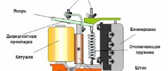
Design and principle of operation of a fan with a humidity sensor.
The difference between fans with a humidity sensor and conventional ones is that such fans have a built-in sensitive element that responds to changes in the humidity level, a relay that closes the electrical circuit and a timer (exactly the same as in a fan with a timer), which essentially controls a fan with a humidity sensor.
But why does a fan with a humidity sensor need a timer? As mentioned above, it is the timer that controls the fan with a humidity sensor. Let's look at the example of turning on and off a correctly connected fan with a humidity sensor. The connection diagram for a fan with a humidity sensor is similar to the connection diagram for a fan with a timer and is shown in the figure below.
From this diagram it can be seen that from the line (phase) to the lighting, two wires to the fan (L) and (SL) are removed. So the wire (L) goes directly to the engine, and the wire (SL) is an information wire. That is, when a person turns on the light, a signal is sent to the board, and the relay, in turn, closes the circuit of the fan motor and the fan will thus work as long as the light is on. When the light turns off (the signal stops coming to the board), the fan continues to work, because the fan timer is activated and then the timer gives a command to turn off the electric motor (the shutdown time is set by turning a screw located under the fan cover in an easily accessible place, the shutdown time can adjustable from 2 to 30 minutes). That is, as long as the light is on, the sensitive element (humidity sensor) does not in any way affect the operation of the fan with a humidity sensor.
But when the light is turned off (that is, there is no one in the room), the humidity sensor begins to manifest itself. If the humidity level exceeds the value set on the fan (set by turning the screw located under the cover of the device), the fan will start working, but the question arises: after what time will the fan turn off? It is sometimes mistakenly believed that the fan will turn off when the humidity level drops, but this is not the case. In fact, after the humidity sensor has started the fan, the timer is activated again, and thus the fan will turn off after the time set by the timer, exactly the same as in the first case considered.
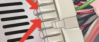
In the figure above, three terminals for connection and adjusting screws are clearly visible (“timer” - red under the inscription timer and humidity sensor - blue under the inscription “hygro”). The adjusting screws are located in an easily accessible location and for resetting you do not need to dismantle the fan with a humidity sensor .
Connecting a bathroom timer
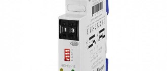
As an example of connection, we use the popular Granit-BZT-300-SU timer from the Nootekhnika company. It will work in tandem with an S&P Silent 100 exhaust fan.
The device itself is quite compact, you can see it in the image below. The maximum power of the fan connected to it should not exceed 300W.
As you can see, the timer has six contacts for connection, all of which are used during installation. And although it looks quite scary, there is nothing complicated here, especially if you understand the connection diagram.
Installing a device with a humidity sensor
For optimal operation of the device and effective air ventilation in the room, it must be connected correctly. What do you need to know about this?
Before installing the device instead of a grille on a ventilation system, you need to check the draft in the ventilation duct. To do this, you need to light a match and bring it to the well; if the flame deviates intensely towards the hole, then natural ventilation is working normally.
When the product is operating, a constant supply of fresh air is needed for air exchange: a small gap of 2-3 cm in the door is suitable for this, which will provide ventilation.
When choosing a product based on power, you need to know the volume of the room and the relative amount of air mass replacement in the bathroom per unit of time. For a bathroom this figure is 3-8 times.
By multiplying the volume by this parameter, we obtain the power characteristics of the device. If you are afraid of making a mistake in your calculations, then you just need to choose the model with the maximum power - and such a fan is guaranteed not to create problems with the necessary air circulation.
It often becomes necessary to purchase a moisture sensor separately and then connect it to the fan. Such hygrometers are usually mounted in the bathroom on the ceiling or near the duct, and in this case they are equipped with a probe for measuring dampness in the air duct shaft.
It is advisable to install a low-voltage fan in the bathroom, since moist air is a good electrical conductor. Sometimes it is better to combine the light and air moisture sensor under one switch, this will ensure regular ventilation as there is excess dampness in the bathroom.
It is enough to follow these simple rules to ensure reliable and long-term operation of the fan. And if you use devices with additional functions, including an exhaust fan with a humidity sensor, then this device will not only be useful, but also a very necessary device for the bathroom.
Agree, buying such a device is a rare acquisition in life and it is better to have a worthy product than to later regret the purchase.
Source