The power supply is the PC hardware component that supplies power to the internal devices. It receives it from the home electrical network and converts alternating current into direct current, which is needed by the computer elements. And it also regulates the voltage within the computer network to an operating level, which allows the machine to operate stably and not overheat. It is an integral part of any PC and must work properly for other components to function reliably. Therefore, if the power supply does not start, the user needs to check it and, if necessary, repair or replace it.
All about power supplies
AC mains current cannot be directly supplied to the PC because its components use DC power and must first undergo a rectification process. This transition determines the main task of the power supply unit (PSU) as an AC rectifier.
The source is designed in such a way that it guarantees standard voltage to all PC components. To do this, it distributes the power across different cables with operating voltages. For example, a DVD hard drive connector provides 5 volts for the electronics and 12 volts for its drive motor.
PC components have different connections, but each source has all the necessary connectors for a standard assembly. Particularly important: the unit must have enough plugs for hard drives and CD/DVD drives that additional drives can be easily installed.
Most office PCs have a small 300W model. A PC adapter that supports gaming should provide at least 400W of power because strong processors and fast graphics cards require a lot of power. In this case, a failure may occur where the power supply starts and turns off immediately.
If your PC runs multiple video cards, you may need a 500 or 650 W model. Currently, devices with a power of 1,000 watts are sold. But they are rarely applicable. If you purchase a low-power unit, the computer may fail, for example, while playing games or watching videos. This happens because the corresponding PC components consume a lot of energy. Overheating is the main reason why a power supply won't start.
What is a power supply?
A computer power supply is a device that generates the voltage necessary for normal operation of the computer by converting the current that flows into it from the general electrical network. In Russia, the device converts alternating current from the general power supply network of 220V and a frequency of 50Hz into several indicators of direct current of low values: 3.3V; 5V; 12V, etc.
The main thing you should look at when buying an electrical appliance is its power, which is measured in watts (W). The more power the computer consumes, the more power the power supply should have.
Budget computers, which are often purchased to equip offices or schools, consume about 300-500 watts. If the model is not cheap - for gaming or for working with heavy engineering or editing programs, then the power of such a computer is about 600 W. In addition, there are models that need power per kilowatt, but these are computers with top-class video cards, which the average user rarely has.
The power supply acts as the energy core of a desktop computer, because it supplies voltage to all components of the computer and allows the computer to continue working and not fail due to current fluctuations. First, the power supply is connected to the general network through an outlet, and then connected to the computer. It distributes the voltage that a particular part requires across the entire PC.
Looking for external storage for your PC? Then you will be interested in our article about which hard drive (SSD) to buy for a laptop.
Usually, many cables go from the computer power supply to the PC itself: to the motherboard, hard drive, video card, drive, fan, etc. The better and better the quality of the unit, the more stably it reacts to the fact that a voltage drop occurs in the general network. It is precisely the fact that the power supply always produces a constant voltage, regardless of what is happening in the general network and protects the desktop computer and its individual components from breakdowns and wear.
If the computer has even the best video card, motherboard and modern cooling system, and the power supply cannot cope with the task assigned to it, then all the power of the components is useless.
Description of ATX DC Power Supply
The ATX unit is a power converter. It converts the alternating current (AC) supplied by the power supply company into direct current (DC) with the required voltage level sufficient for the PC components, which corresponds to 110-115 or 220-230 volts.
This conversion is performed using the processes:
- switching;
- straightening;
- filtration.
Many PCs have a unit called SMPS or pulse. When the switching power supply fails to start and needs to be tested, users must strictly follow the safety precautions and precautions to protect against electric shock. The power supply contains dangerous voltages and currents. There are capacitors inside that store energy and can cause electric shock, so repairs to the unit should only be performed by qualified personnel.
Recommendations and protective measures in cases where the ATX power supply does not start:
- The user can easily find the source on the system unit by seeing the input to which the cord is connected, without opening the computer.
- If you unplug and remove the PSU, it will look like a metal box with a fan inside and several cables attached to it.
- The average user is not recommended to disconnect the power supply; it is better to leave it in the case.
PSU: computer hardware component
PS, P/S or PSU are abbreviations for power supply unit. Below is a list of items that come with the power supply:
- Power cord to computer.
- Housing to prevent dust from entering the power supply.
- Fan for cooling and air removal.
- Switch for changing voltage.
- Cable packages located on the front internal panel of the power supply unit. They connect to the computer's motherboard and internal components. Therefore, if the power supply does not start, the motherboard is the first device that will stop working.
- Drive connectors.
- The motherboard connector is a 24-pin ATX connector which, when connected, provides power to the motherboard.
- Input voltage selector.
The ATX function block provides +5V, 720mA standby current through the purple wire to the motor pin. This current is also supplied to the PCI slots even when the computer is turned off and damaged. Therefore, when the power supply does not start, there is a duty officer. Therefore, it is recommended that when turning off the power supply, wait 30 seconds before starting work inside the system unit in order to take proper precautions against electrostatic discharge.
Diagnosis of nutrition problems
Power problems can be difficult to diagnose, especially if the user doesn't know what to look for. Here are some tips on how to quickly identify the problem if the power supply does not start and how to resolve this failure.
A bad source can be the cause of many PC problems. Experience can help a technician diagnose problems caused by a faulty source that is usually ignored by new technicians.
Any intermittent problem may be caused by a faulty source. Common symptoms when a computer power supply does not start:
- Failure when turning on voltage.
- Spontaneous reboot or intermittent blocking during stable operation.
- Memory errors.
- HDD and fan do not rotate.
- Overheating due to the fan being turned off.
- Frequent shutdowns that cause system restarts.
- Electric shocks that are felt when touching the body.
There are also some obvious clues that should answer the question of why the power supply won't start. These include:
- A system that is completely dead, nothing happens in it when the PC is turned on.
- Smoke that appears when you turn on your PC.
Another way to check the power supply is to use special software. It can detect changes in temperature or performance, and will show how much power is being supplied to which components, which will help solve the problem faster.
Power supply repair
If you have sufficient confidence in using a soldering iron, repairing a power supply with your own hands is not so difficult, especially since most operations come down to replacing simple parts with two or three pins that do not require special skills or equipment for dismantling.
Since the question “how to repair a computer power supply” is unlikely to arise for a person who professionally owns the appropriate tool (soldering station, desoldering pump, etc.), in the future we will proceed from the minimum set of the most common devices.
Therefore, we will need
- soldering iron with a power of up to 65 W with a flat sharpened tip,
- solder,
- acid-free flux (rosin),
- tweezers and a flat screwdriver.
Excess solder can be removed using stripped stranded copper wire submerged into a drop of molten tin.
When replacing large-sized elements like capacitors, you need to sequentially heat the soldering points of their legs, remove excess solder if possible, and then either alternately warm up the legs and tilt the capacitor body from side to side to remove it, or, if the size of the soldering iron tip allows this, heat both points simultaneously solder and quickly pull the capacitor out of the holes in the board. In this case, as when working with other elements, it is important to minimize the time the soldering iron is exposed to the board and the part.
When replacing transistors and powerful diodes, they are installed in the holes on the board so that the mounting hole coincides with the threads in the radiator body. Before attaching to the radiator, the surface of the part is lubricated with thermal conductive paste (KPT-8 or its analogues).
When replacing an electrolytic capacitor or diode, you must remember that these are polar elements, and their installation must strictly correspond to the drawing on the board (for capacitors, except tantalum, the strip indicates the negative pole).
After repairing the power supply, you should not rush to install it in the computer - it is best to repeat the check described earlier.
Electrical test of power supply
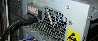
First, make sure that the computer is connected to the mains through an outlet. If necessary, you can use a lamp or hair dryer to make sure the electrical outlet is working. In some cases, there is a switch on the power supply, make sure it is on. Sometimes the unit may have a smaller red switch installed to select the voltage type.
Latest power supplies sometimes have an electrical filter that prevents the computer from rebooting after a short circuit. To fix this glitch, simply unplug the power cord from the computer, then press and hold the power button for a few seconds to discharge the accumulated energy and reset the protection.
The power supply works correctly if the voltage in the wires corresponds to the following parameters:
- blue + 11.20 V;
- yellow + 11.20 V;
- purple + 5.20 V;
- orange + 3.33 V;
- red + 5.20 V;
- white + 5.20 V;
- gray + 5.20 V.
Power supplies are not designed to operate in standby mode, so voltages may vary slightly from the table below and for this reason the supply should only be operated in this manner for a short time. Voltage by contact numbers:
- No. 1 - 3.3 V;
- No. 2 - 12 V;
- No. 3, 5, 6, 7 - GND;
- No. 4 - food;
- No. 8 - 5 V;
- No. 9, 10 - 5 V;
- No. 11, 12 - 3.3 V;
- No. 13, 15, 17 - GND;
- No. 14, 16 - 5 V;
- No. 18 - PW-OK;
- No. 19 - 5 V;
- No. 20 - 12 V.
For current power supplies, the Power/On control line is usually green.
Simplified ATX Test Method
If the ATX power supply does not start, check that it is operating correctly and that its voltages comply with the manufacturer's specifications. To perform these tests, use a screwdriver to open the box and a cable to bypass the power. In this case, use a simple paperclip and one multimeter to perform the necessary measurements. First of all, you need to take certain precautions before opening the PSU case. The source must be unplugged and the power button on the rear panel must be in the off position.
First you need to open the box with a screwdriver and find the power supply connector, consisting of 24 (20 + 4) contacts. Once found, disconnect it from the motherboard. The next step is to find a green wire called PS_ON (PowerSupply ON), which is connected to the common black cable of the PSU. Using a jumper with a clamp, the green wire is connected to any black wire of the connector, after which the source will be artificially turned on without the need to connect the base board. After this, connect the power cable to the mains and press the button on the rear panel to turn it on. In order to make sure that the bridge is made correctly, turn on the power source, and if the fan rotates and drives air, then everything is done correctly.
Now you need to take measurements, for which you use a multimeter. Red and black connectors are located in the tension measurement position: black connector for COM and red for V Hz.
The rotary switch is located in the DC voltage measurement area at position 20 as it will measure voltages of 3.3V, 5V and 12V.
Checking the power supply
Although a pulse power supply is not an entry-level radio-electronic circuit, its DIY diagnostics and repairs are accessible to many people who have basic knowledge and skills in the field of radio electronics. Let's consider a typical procedure for checking a power supply removed from a computer:
- Connect powerful load resistors rated for a current of about 1A and the corresponding power to the +3.3V, +5V and +12V terminals. This is necessary to avoid incorrect operation of some units without load.
- Apply mains power to the unit.
- Check for voltage on the +5VSB line. It should occur immediately after the block is connected to the network.
- Connect the PS-ON terminal to the power supply housing. In this case, the corresponding voltages must be set at the power outputs of the power supply unit and the PG output.
Possible faults:
- There is no standby voltage when the power is turned on. If the power supply starts up and generates controlled voltages, check the operation of the standby voltage pulse converter (the presence of pulses on the primary winding of its transformer), the serviceability of the rectifier (the presence of a constant voltage of at least 9V at the input of the 7805 microcircuit) and the operation of the stabilizer (the output of the 7805 microcircuit should be +5V).
- If there is standby voltage, but the power supply does not start, try to force the PWM controller to start as follows:
- If there is no generation of pulses on the indicated legs of the microcircuit, it will need to be replaced. Otherwise, you should pay attention to the output stage of the converter, especially the switching transistors.
- If there is no standby voltage and the power supply does not start, check the input rectifier sequentially: the integrity of the fuse and thermistor, the absence of breaks in the inductor windings. However, the most common malfunction is the burnout of the diode bridge as a result of a short circuit in the filter capacitor. This will be immediately noticeable both by the characteristic smell and by the burnt diodes.
- If there is no voltage at only one of the controlled power outputs, you should first of all pay attention to the rectifier diode and filter capacitor of this circuit.
A quick note about polarity
If the power supply does not start the first time, when checking, you need to ensure the polarity of the measurements with a multimeter. Place the black multimeter measuring wire in any common cable, and the red one in turn in a cable of different colors, which are located in the power supply connector. Voltages are measured to ensure compliance with the certified values specified by the manufacturer. All voltages that will be determined are constant. The power supply wires are color coded.
The test leads are also color coded: red is positive (+) and black is negative (-). To check the output voltage on the motherboard, place the black test lead on the black pin and the red test lead on the Power_Good pin (P8-1) of the AT, Baby AT and LPX power supplies, and pin 3 on the 20-pin ATX connectors. It should read +3 to +6 volts DC. If the user does not see this voltage, then the unit is faulty.
Any voltage within 10 percent of the specified voltage is acceptable for testing purposes. Some problems cannot be detected by direct measurement, so having replacement inventory is essential.
Revision using the advanced tester
The following instructions only apply to the dedicated ATX Coolmax PS-228 power supply tester, or any other similar tester with an LCD screen.
Important: This process is considered complex, the user needs to carefully follow the instructions below.
Time required: Testing a PSU with a PSU test device usually takes about 30 minutes, or a little more for beginners.
Algorithm of actions:
- Learn important safety tips when repairing your PC. Testing a power supply involves working with high voltage electricity, a potentially hazardous activity. Safety should be the main concern during a block inspection.
- Open the case by first turning off the computer, disconnecting the power cord and everything connected to the outside of the computer.
- Move the disconnected unit to a place where you can easily work, such as a desk. The user will not need a keyboard, mouse, monitor or other external peripheral devices.
- Disconnect the power connectors of each internal unit on the side panel. An easy way to ensure that each power connector is unplugged is to remove the power cord kit that comes from the PSU. Each group of cables must end with one or more power connectors. There is no need to disconnect data cables or other cables that are not connected to the power supply.
- Group all power cables and connectors for easy testing. When organizing power cables, it is recommended to disconnect them and remove them from the computer case as far as possible. This will make connecting the power connectors to the extended tester as easy as possible.
- Make sure the power supply voltage switch located on the rear panel is correctly set for your country of residence. In the US this switch should be set to 110V/115V, and in Russia to 220/230.
- Connect the 24-pin ATX power connector and the 4-pin ATX power connector on the motherboard in the PC power supply tester. Depending on the source, there may not be a 4-pin motherboard connector, but there may be 6 or 8 pins. If there is more than one type, simply connect one at a time along with the 24-pin main power connector.
- Connect the power supply to an electrical outlet and turn on the switch. Some units do not have a switch on the rear panel. If the source being tested does not work, simply connect the device to supply power. Press and hold the on/off button of the tester for PC power supplies. The user should hear the fan inside the source start to operate.
Some versions of the improved Coolmax PS-228 power supply tester do not require constantly pressing the power button. Just because the fan is running doesn't mean the power supply is properly supplying power to the rest of your devices. If the power supply fan does not start during testing, even if the source is in good condition, it may be burnt out and should be checked separately.
The Advanced Source Tester's LCD display should be turned on and the user will see test numbers for all metrics. If the voltage shows "LL" or "HH" or if the LCD does not light up, the PSU is not working and will need to be replaced.
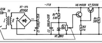
Power supply device
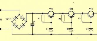
A typical ATX power supply circuit is shown in the figure. Structurally, it is a classic pulse unit on a TL494 PWM controller, triggered by a PS-ON (Power Switch On) signal from the motherboard. The rest of the time, until the PS-ON pin is pulled to ground, only the Standby Supply with a voltage of +5 V at the output is active.
Let's take a closer look at the structure of the ATX power supply. Its first element is a network rectifier :
Its task is to convert alternating current from the mains to direct current to power the PWM controller and standby power supply. Structurally, it consists of the following elements:
- Fuse F1 protects the wiring and the power supply itself from overload in the event of a power supply failure, leading to a sharp increase in current consumption and, as a consequence, to a critical increase in temperature that can lead to a fire.
- A protective thermistor is installed in the neutral circuit, which reduces the current surge when the power supply is connected to the network.
- Next, a noise filter is installed, consisting of several chokes ( L1, L2 ), capacitors ( C1, C2, C3, C4 ) and a counter-winding choke Tr1 . The need for such a filter is due to the significant level of interference that the pulse unit transmits to the power supply network - this interference is not only picked up by television and radio receivers, but in some cases can lead to the malfunction of sensitive equipment.
- A diode bridge is installed behind the filter, converting alternating current into pulsating direct current. Ripple is smoothed out by a capacitive-inductive filter.
Next, the constant voltage, present all the time while the ATX power supply is connected to the outlet, is supplied to the control circuits of the PWM controller and the standby power supply.
The standby power source is a low-power independent pulse converter based on transistor T11, which generates pulses through an isolation transformer and a half-wave rectifier on diode D24, feeding a low-power integrated voltage stabilizer on the 7805 chip. Although this circuit is, as they say, time-tested, it is not a significant drawback is the high voltage drop across the 7805 stabilizer, which leads to overheating under heavy load. For this reason, damage in the circuits powered from the standby source can lead to its failure and subsequent inability to turn on the computer.
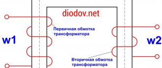
The basis of the pulse converter is a PWM controller . This abbreviation has already been mentioned several times, but has not been deciphered. PWM is pulse width modulation, that is, changing the duration of voltage pulses at their constant amplitude and frequency. The task of the PWM unit, based on a specialized TL494 microcircuit or its functional analogues, is to convert DC voltage into pulses of the appropriate frequency, which, after an isolation transformer, are smoothed by output filters. Voltage stabilization at the output of the pulse converter is carried out by adjusting the duration of the pulses generated by the PWM controller.
An important advantage of such a voltage conversion circuit is also the ability to work with frequencies significantly higher than 50 Hz of the power supply. The higher the frequency of the current, the smaller the dimensions of the transformer core and the number of turns of the windings are required. That is why switching power supplies are much more compact and lighter than classical circuits with an input step-down transformer.
A circuit based on transistor T9 and the stages following it are responsible for turning on the ATX power supply. At the moment the power supply is turned on to the network, a 5V voltage is supplied to the base of the transistor through the current-limiting resistor R58 from the output of the standby power supply; at the moment the PS-ON wire is shorted to ground, the circuit starts the PWM controller TL494. In this case, failure of the standby power source will lead to uncertainty in the operation of the power supply starting circuit and a possible switching failure, as already mentioned.
The main load is borne by the output stages of the converter. First of all, this concerns switching transistors T2 and T4, which are installed on aluminum radiators. But under high loads, their heating, even with passive cooling, can be critical, which is why power supplies are additionally equipped with an exhaust fan. If it fails or is very dusty, the probability of overheating of the output stage increases significantly.
Modern power supplies are increasingly using powerful MOSFET switches instead of bipolar transistors, which, due to significantly lower open resistance, provide greater converter efficiency and are therefore less demanding on cooling.
Video about the design of a computer's power supply, its diagnostics and repair
Pinout of the main PSU connector
ATX 20-pin to connect to the motherboard . Now it can only be found on outdated equipment. Subsequently, the growth in the power of personal computers, and consequently their energy consumption, led to the use of additional 4-pin connectors ( 4-pin ). Subsequently, the 20-pin and 4-pin connectors were structurally combined into one 24-pin connector, and for many power supplies, the part of the connector with additional contacts could be separated for compatibility with older motherboards.
Read also: Training to become an electrical engineer remotely
The pin assignments of the connectors are standardized in the ATX form factor as follows according to the figure (the term “controlled” refers to those pins on which the voltage appears only when the PC is turned on and is stabilized by a PWM controller):
| Contact name | Purpose |
| +3.3V | Positive voltage 3.3V, controlled. Power supply for motherboard and processor. |
| +5V | Positive controlled voltage 5V. Power supply for parts of the motherboard, hard drives, and external USB devices. |
| +12V | Controlled voltage 12V for hard drives, cooling system fans. |
| -5V | Controlled voltage -5V. The ATX standard is no longer used starting from version 1.3. |
| -12V | Controlled voltage -12V. Practically not used. |
| Ground | Weight. |
| PG | It has a high level provided that the voltage exceeds the lower threshold of 5V and 3.3V (signals that the power supply is entering operating mode). |
| +5VSB | Constant voltage 5V (standby source). |
| PS-ON | Turning on the power supply when the output is shorted to ground. |
Monitoring peripheral power connectors
If you need to check individual connectors, continue testing the power supply. Verification algorithm:
- Turn off the switch on the power supply panel and unplug it from the outlet.
- Connect the tester socket connector to the corresponding SATA connector with a 15-pin Molex modification. Do not connect more than one of these peripheral connectors at the same time, otherwise the tester may be damaged.
- Two connectors on the motherboard must remain connected for these tests with other connectors.
- Connect the source, and then turn on the button on the panel.
- The LEDs labeled +12V, +3.3V, and +5V correspond to the voltage supplied through the connected peripheral power connector and should be lit as expected. Otherwise, the power supply needs to be replaced.
- The SATA connector provides +3.3 VDC. You can see the voltage supplied by different connectors by looking at the ATX connector output pin charts.
- Repeat this process for the other power connectors one at a time, except for the connector on the motherboard, which remain connected to the tester at all times.
- After completing the tests, turn off the power supply, disconnect the tester cables, and then connect the internal devices of the PC to the source.
- After the power supply has been tested or replaced with a new one, you can turn on the PC again.
ATX computer power supply circuit
In such a unit, with the help of an inverter, the rectified mains voltage is converted into high-frequency alternating voltage, from which the low voltage flows necessary for computer operation are formed.
The ATX power supply circuit consists of 2 nodes - a mains voltage rectifier and a voltage converter for the computer.
The mains rectifier is a bridge circuit with a capacitive filter. A constant voltage of 260 to 340 V is generated at the output of the device.
The main elements of the voltage converter are:
- an inverter that converts direct voltage into alternating voltage;
- high-frequency transformer operating at a frequency of 60 kHz;
- low-voltage rectifiers with filters;
- control device.
In addition, the converter includes a standby voltage power supply, amplifiers for the control signal of key transistors, protection and stabilization circuits, as well as other elements.
The inverter includes two power transistors operating in switching mode and controlled using signals with a frequency of 60 kHz coming from a control circuit implemented on the TL494 chip. A pulse transformer is used as the inverter load, from which the +3.3 voltages are removed, rectified and filtered V, +5 V, +12 V, -5 V, -12 V.