Motor Driver in Arduino Projects
What is a motor driver for?
As you know, the Arduino board has significant limitations on the current strength of the load connected to it. For the board this is 800 mA, and for each individual pin it is even less, 40 mA. We cannot connect even the smallest DC motor directly to the Arduino Uno, Mega or Nano. Any of these motors, when started or stopped, will produce peak inrush currents exceeding this limit.
How then to connect the motor to the Arduino? There are several options:
Use a relay . We connect the motor to a separate electrical network that is in no way connected to the Arduino board. The relay, at the command of the Arduino, closes or opens the contacts, thereby turning on or off the current. Accordingly, the engine turns on or off. The main advantage of this scheme is its simplicity and ability to use. The main disadvantage of this scheme is that we cannot control the speed and direction of rotation.
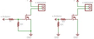
Use a power transistor . In this case, we can control the current passing through the motor, which means we can control the spindle speed. But this method is not suitable for changing the direction of rotation.
Use a special connection circuit called H-bridge , with which we can change the direction of movement of the motor spindle. Today you can easily find both microcircuits containing two or more H-bridges, as well as individual modules and expansion cards built on these microcircuits.
In this article we will consider the last, third option, as the most flexible and convenient for creating the first robots on Arduino.
Motor Shield chip or expansion board
Motor Shield is an expansion board for Arduino that powers DC and stepper motors. The most popular Motor Shield boards are those based on the L298N and L293D chips, which can control multiple motors. The board has a set of Arduino Rev3 through-holes, allowing the installation of other expansion boards. The board also has the ability to select a voltage source - Motor Shield can be powered either from Arduino or from an external source. There is an LED on the board that shows whether the device is working. All this makes using the driver very simple and reliable - there is no need to reinvent the wheel yourself and solve problems that have already been solved by someone else. In this article we will talk specifically about shields.
Operating principle of the H-bridge
The operating principle of the motor driver is based on the H-bridge operating principle. An H-bridge is an electronic circuit that consists of four switches with a load. The name of the bridge comes from the H-shaped configuration of the circuit.
The bridge diagram is shown in the figure. Q1…Q4 0 field-effect, bipolar or IGBT transistors. The latter are used in high-voltage networks. Bipolar transistors are practically not used; they can be present in low-power circuits. For high currents, field-effect transistors with an insulated gate are used. The keys should not be shorted together at the same time to avoid short circuiting the source. Diodes D1...D4 are limiting; Schottky diodes are usually used.
By changing the state of the keys on the H-bridge, you can adjust the direction of movement and brake the motors. The table shows the main states and the corresponding combinations on pins.
| Q1 | Q2 | Q3 | Q4 | State |
| 1 | 0 | 0 | 1 | Turn the motor to the right |
| 0 | 1 | 1 | 0 | Turn the motor left |
| 0 | 0 | 0 | 0 | Free rotation |
| 0 | 1 | 0 | 1 | Braking |
| 1 | 0 | 1 | 0 | Braking |
| 1 | 1 | 0 | 0 | Short circuit |
| 0 | 0 | 1 | 1 | Short circuit |
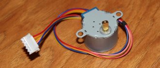
Connecting a stepper motor to Arduino via l293d
Controlling DC motors with L293D
Studying the treatise of a professor from the “school of computer enthusiasts and microrobots” was the last straw that overflowed the cup. It's time to get serious about controlling DC motors. They will move our robot back and forth, and also turn it around. In the vast majority of cases, turns are made by braking one of the drive wheels. The simplest robots have two driving wheels, and the third is solely for support and reducing friction. By the way, one figure on some forum said: “everyone knows that sliding friction, of course, is much less than rolling friction.” Thus he showed ignorance of elementary physics and his pseudo-competence. And that's a fact! It gets sad sometimes, but there is plenty of positive information on the Internet if you don’t hang out on forums.
I will not describe further small details. You can find out about them in previous publications. I will try to work more or less systematically, illustrating each step (if possible) with a practical example.
L298N motor driver
The module is used to control stepper motors with voltages from 5 to 35 V. Using one L298N board, you can control two motors at once. The maximum load provided by the microcircuit reaches 2 A for each motor. If you connect the motors in parallel, this value can be increased to 4 A.
The board looks like this:
L298N chip pinout:
- Vcc – used to connect external power;
- 5V;
- Ground GND;
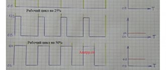
- IN1, IN2, IN3, IN4 – used to smoothly control the motor rotation speed;
- OUT1, OUT2 – used for output from the first motor;
- OUT3, OUT4 – used for output from the second motor;
- S1 – switches the power supply to the circuit: from an external source or from an internal converter;
- ENABLE A, B – required for separate control of channels. They are used in two modes - active, in which the channels are controlled by a microcontroller and it is possible to change the rotation speed, and passive, in which it is impossible to control the speed of the motors (the maximum value is set).
When connecting two motors, you need to check that they have the same polarity. If the polarity is different, then when the direction of movement is set, they will rotate in opposite directions.
How to connect Motor Shield to Arduino
For this lesson we will need:
The shield is connected to Arduino very simply - it is installed on the UNO board directly from above. Please note that without connecting an external power supply to the Motor Shield, the logic and motors will run on 5 Volts, which is not always sufficient. Therefore, the rotation speed of DC motors when connecting the Arduino board from the computer and the power supply will differ significantly.
Motor Shield Arduino connection diagram
Please note that even if you set the same rotation speed in the sketch, the motors in reality can rotate at different speeds - this is influenced by the speed of the motor itself, the quality of the gearbox and wheels. After connecting the motors, as in the diagram above, download the following sketch (you can download the AFMotor library and the sketch here) to test the operation of the shield:
Sketch for Motor Shield L293D Arduino and motors
Explanations for the code:
Sketch for connecting servo and stepper motors
To control the servos, the standard Servo.h library is used; the servos themselves are connected to digital outputs 9 and 10 via pins on the edge of the board. Only two servos and two stepper motors can be connected to the shield. The first stepper motor is connected to terminals M1 and M2, and the second to terminals M3 and M4. The diagram for connecting motors to Motor Shield L293D is shown below.
Connecting stepper motors to Motor Shield L293D
After connecting the Stepper Motor to the shield, upload the following sketch to the board:
Source
L293D motor driver
L293D is the simplest microcircuit for working with engines. The L293D has two H-bridges that allow you to control two motors. The operating voltage of the microcircuit is 36 V, the operating current reaches 600 mA. The L293D motor can supply a maximum current of 1.2A.
The circuit has 16 outputs. Pinout:
- +V – 5 V power supply;
- +Vmotor – supply voltage for motors up to 36 V;
- 0V – ground;
- En1, En2 – turn H-bridges on and off;
- In1, In2 – control the first H-bridge;
- Out1, Out2 – connection of the first H-bridge;
- In3, In4 – control the second H-bridge;
- Out3, Out4 – connection of the second H-bridge.
To connect to the Arduino Uno microcontroller, you need to connect outputs In1 on L293D and 7 pins on Arduino, In2 – 8, In3 – 2, In4 – 3, En1 – 6, En2 – 5, V – 5V, Vmotor – 5 V, 0V – GND . An example of connecting one motor to Arduino is shown in the figure.
Connection diagram for Motor Shield L293D and Arduino
Connecting the shield to the Arduino is done in the standard way, namely by direct connection, making a “sandwich”. You can see how to do this in the photo below.
After connecting the Motor Shield L293D to the Arduino, we need to connect the remaining components. The correct connection is shown in the photo below.
Most likely, the connection did not cause you any problems, since it is very simple. It's time to move on to a more important procedure - programming.
Motor driver on HG7881 chip
HG7881 is a two-channel driver that can connect 2 motors or a four-wire two-phase stepper motor. The device is often used due to its low cost. The driver is used only to change the direction of rotation; it cannot change the speed.
The board contains 2 L9110S circuits that work as an H-bridge.
HG7881 driver specifications:
- 4-pin connection;
- Power supply for motors from 2.5 V to 12 V;
- Current consumption less than 800 mA;
- Small dimensions, light weight.
Pinout:
- GND – ground;
- Vcc – supply voltage 2.5V – 12V;
- A-IA – input A(IA) for motor A;
- A-IB – input B (IB) for motor A;
- B-IA – input A(IA) for motor B;
- B-IB – input B (IB) for motor B.
Depending on the signal applied, outputs IA and IB will have different states for the motors. Possible options for one of the motors are shown in the table.
| I.A. | I.B. | Motor condition |
| 0 | 0 | Stop |
| 1 | 0 | Moving forward |
| 0 | 1 | Moves backwards |
| 1 | 1 | Shutdown |
Connecting one motor to Arduino is shown in the figure.
Comparison of modules
The L293D module supplies a maximum current of 1.2A, while the L298N can achieve a maximum current of 4A. The L293D also has lower efficiency and heats up quickly during operation. At the same time, L293D is the most common board and is inexpensive. The HG7881 board differs from the L293D and L298N in that it can only be used to control the direction of rotation; it cannot change the speed. HG7881 is the cheapest and smallest module.
Connecting the motor shield to Arduino
L293D motor shield Arduino ► consider connecting to the Arduino board, AFMotor library commands for controlling servo and DC motors from the L293D.
Today we will analyze a very useful extension for the Arduino UNO board - Motor Control Shield L293D, we will look at the diagram for connecting servomotors, stepper motors and DC motors to this shield. You can also familiarize yourself with the commands used in the AFMotor.h and try various sketches for controlling stepper motors and DC motors on Arduino.
Connecting L298N to Arduino
As already mentioned, first of all you need to check the polarity of the connected motors. Motors that rotate in different directions are difficult to program.
You need to connect a power source. + connects to pin 4 on the L298N board, minus (GND) – to pin 5. Then you need to connect the outputs from the L298N and the pins on the Arduino, some of which must support PWM modulation. On the Arduino board they are marked ~. Connect the outputs from L298N IN1, IN2, IN3 and IN4 to D7, D6, D5 and D4 on the Arduino, respectively. The connection of all other contacts is shown in the diagram.
The direction of rotation is specified using the HIGH and LOW signals on each channel. The motors will start rotating only when there is a HIGH signal on pin 7 for the first motor and pin 12 for the second on the L298N. Feed LOW stops rotation. To control the speed, PWM signals are used.
To control a stepper motor in the Arduino IDE, there is a standard Stepper library. To check the functionality of the assembled circuit, you can download the test example stepper_oneRevolution. When assembled correctly, the motor shaft will begin to rotate.
When working with motors, Arduino may periodically reboot. This occurs due to the fact that motors require large currents at start and during braking. To solve this problem, capacitors, diodes and other circuits are built into the board. Also for these purposes, the shidla has separate power supply.
It's time for Arduino to control the motors. To do this, we will use the most popular driver used to control motors - the L293D chip.
L293D
contains two drivers for controlling low-power electric motors. It has two pairs of inputs for control signals and two pairs of outputs for connecting electric motors. In addition, the L293D has two inputs to enable each of the drivers. These inputs are used to control the rotation speed of electric motors using PWM.
Let's look at the L293D block diagram given in the datasheet ( numbering for SO-case
):
The MOTOR1 electric motor is connected to the OUTPUT1 and OUTPUT2 outputs (for a chip in a DIP package - pins 3 and 6
).
Accordingly, MOTOR2 is connected to the outputs OUTPUT3 and OUTPUT4 (pins 11 and 14
).
Signals supplied to ENABLE1(2) control the corresponding driver (pins 1 and 9, respectively).
By applying the HIGH signal to the ENABLE1 input (or simply connecting it to the plus of the +5V power source), we turn on the driver of the 1st motor. If no signals are supplied to the INPUT1 and INPUT2 inputs, the motor will not rotate. By feeding HIGH to INPUT1 and LOW to INPUT2 we will make the motor rotate. And if we now swap the signals and apply a LOW signal to INPUT1, and a HIGH signal to INPUT2, we will make the motor rotate in the other direction.
Likewise for the second driver.
Vss output (pin 16
) is responsible for powering the microcircuit itself, and the Vs output (pin
8
) is responsible for powering the motors - this ensures separation of the power supply for the microcircuit and for the motors it controls, which allows you to connect electric motors with a supply voltage different from the supply voltage of the microcircuit.
Separating the power supply to the chips and the motors is also necessary to reduce noise caused by voltage surges associated with the operation of the motors.
The four GND pins (pins 4, 5, 12,13) need to be connected to ground. These contacts also provide heat removal from the microcircuit.
Specifications L293D
motor supply voltage (Vs) from 4.5 to 36V microcircuit supply voltage (Vss) 5V permissible load current 600mA (per channel) peak (maximum) output current 1.2A (per channel) logical “0” input voltage up to 1.5V logical “1” input voltage 2.3…7V switching speed up to 5 kHz.
If you use the L293E
, then the permissible load current for each channel will already be 1A (and the peak current – 2A),
but you will have to use external protective diodes, which in the L293D are built into the chip itself.
Let's try to simulate how Arduino copes with motor control
Launch Proteus and open the project with Arduino. Add our driver to the circuit - L293D
Let's connect the Vss and Vs pins to the positive pole of the battery, connect the GND pins to ground, and connect the motors to pins 3.6 and 11.14 - MOTOR1 and MOTOR2, respectively.
In a real circuit - you need to solder a capacitor in parallel to the motor - it helps to cope with interference from a running electric motor (this is a common practice - disassemble any toy with a motor and you will see that a ceramic capacitor with a nominal value of about 0.1 uF is soldered directly to the motor)
How to connect the driver inputs? First, let's see how it works in practice. Load the Blink or Blink_HL sketch into the MK, and then, as shown in the figure, connect INPUT1 and ENABLE1 to digital pin 13, to which the LED is connected, and connect INPUT2 to ground. Let's run the simulation and see that the motor rotates in one direction for one second, and then stops for a second. Those. got a motorized Blink
So, it turns out that three ports
(one of them is PWM).
If you do not need to control the motor rotation speed, you can save on PWM ports (ENABLE1 and ENABLE2). Then, to control one motor you will need to use two ports
.
So, let’s decide on the ports (in parentheses - the corresponding number of the MK pin from pin mapping):
MOTOR1 11 (17) – PWM ENABLE1 12 (18) INPUT2 13 (19) INPUT1 MOTOR2 7 (13) INPUT3 8 (14) INPUT4 9 (15) – PWM ENABLE2
Let's change our project in Proteus:
Now let's write a sketch.
For convenience, we will store port numbers not in ordinary variables of the int type, but will combine them with a structure:
struct MOTOR // structure for storing the numbers of pins to which the motors are connected { int in1; // INPUT1 int in2; // INPUT2 int enable; // ENABLE1 };
however, if you simply declare such a structure in the sketch code, for example like this:
/* * test sketch with L293 */ struct MOTOR // structure for storing the numbers of pins to which the motors are connected { int in1; // INPUT1 int in2; // INPUT2 int enable; // ENABLE1 }; // determine the ports to which the motors are connected MOTOR MOTOR1 = { 13, 12, 11 }; MOTOR MOTOR2 = { 7, 8, 9 }; void set_m_pins(MOTOR *m); void setup() { set_m_pins(&MOTOR1); set_m_pins(&MOTOR2); Serial.begin(9600); } void loop() { delay(1000); } void set_m_pins(MOTOR *m) { if(m) { pinMode(m->in1, OUTPUT); pinMode(m->in2, OUTPUT); } }
Then, when we try to compile, we get an error:
error: variable or field 'set_m_pins' declared void In function 'void setup()':
- the point is that additional data structures must be declared in header (.h) files. Those. you need to create a library file and connect it to the sketch using the #include directive
However, here the compiler does not like accessing the new data type by pointer.
Let's change the sketch:
/* * test sketch with L293 */ struct MOTOR // structure for storing the numbers of pins to which the motors are connected { int in1; // INPUT1 int in2; // INPUT2 int enable; // ENABLE1 }; // determine the ports to which the motors are connected MOTOR MOTOR1 = { 13, 12, 11 }; MOTOR MOTOR2 = { 7, 8, 9 }; void setup() { Serial.begin(9600); pinMode(MOTOR1.in1, OUTPUT); // set up pins pinMode(MOTOR1.in2, OUTPUT); // to OUTPUT pinMode(MOTOR2.in1, OUTPUT); pinMode(MOTOR2.in2, OUTPUT); } void loop() { forward1(); // rotate both motors forward forward2(); delay(3000); back2(); // rotate the second motor back delay(500); forward2(); // now rotate the second motor forward again } void forward1() // first forward { digitalWrite(MOTOR1.in1, HIGH); digitalWrite(MOTOR1.in2, LOW); analogWrite(MOTOR1.enable, 254); } void forward2() // second forward { digitalWrite(MOTOR2.in1, HIGH); digitalWrite(MOTOR2.in2, LOW); analogWrite(MOTOR2.enable, 254); } void back1() // first back { digitalWrite(MOTOR1.in1, LOW); digitalWrite(MOTOR1.in2, HIGH); analogWrite(MOTOR1.enable, 254); } void back2() // second back { digitalWrite(MOTOR2.in1, LOW); digitalWrite(MOTOR2.in2, HIGH); analogWrite(MOTOR2.enable, 254); }
For three seconds both motors rotate forward, then for half a second the second motor rotates backward, and then forward again.
Let's transfer the structure and functions to our RoboCraft library.
/* * robocraft.h * * RoboCraft — library fo RoboCraft.ru project * RoboCraft — library for the RoboCraft.ru project * * * Written by noonv, August 2009. */ #ifndef robocraft_h #define robocraft_h #include “WProgram.h” #define _RCDEBUG_ 1 struct MOTOR // structure for storing the numbers of pins to which the motors are connected { int in1; // INPUT1 int in2; // INPUT2 int enable; // ENABLE1 }; class RoboCraft { public: RoboCraft(); RoboCraft(MOTOR *m1, MOTOR *m2); void hello(); void motor_forward(int m,int speed=254); void motor_back(int m, int speed=254); private: void set_m_pins(MOTOR *m); void m_forward(MOTOR *m,int speed=254); void m_back(MOTOR *m,int speed=254); MOTOR MOTOR1; MOTOR MOTOR2; }; #endif // #ifndef robocraft_h And the sketch then will be like this: #include // // test sketch with L293 // added test functions for working with motors via L293 // // // by noonv // MOTOR MOTOR1 = { 13, 12, 11 }; MOTOR MOTOR2 = { 7, 8, 9 }; RoboCraft robot(&MOTOR1, &MOTOR2); // create an instance of our class void setup() { Serial.begin(9600); robot.hello(); // say “Hello” } void loop() { Serial.println(“loop”); robot.motor_forward(0,254); // both full speed ahead delay(3000); robot.motor_back(2,254); // turn the second one back delay(1000); robot.motor_forward(2,254); // and again 2nd forward! }
Rotation functions take two parameters - motor number (1-2) and rotation speed (0-255). If the number differs from 1-2, then rotation is assigned to both motors at once.
I had the L293E chip on hand - so I need to use protective diodes (1N4007), of which two motors require as many as 8 pieces
Also, the L293E has not 16, but as many as 20 legs:
However, for testing you can assemble a circuit for only one motor 
Accordingly, you need to make changes to the sketch:
MOTOR MOTOR1 = { 13, 12, 11 }; MOTOR MOTOR2 = { 7, 8, 9 }; RoboCraft robot(&MOTOR1, &MOTOR2); // create an instance of our class void setup() { Serial.begin(9600); robot.hello(); // say “Hello” } void loop() { Serial.println(“loop”); robot.motor_forward(0,254); // full speed ahead delay(3000); robot.motor_back(1,254); // turn back delay(1000); } — we turn our motor 3 seconds forward, and then one second back.
Spinning
read more
A simple motor shield for Arduino/CraftDuino A few more words about the L293 L-Motor Shield
Links
L293D MOTOR DRIVER https://www.arduino.cc/playground/Code/Struct
Class AF_DCMotor
The AF_DCMotor class provides the ability to control the speed and direction of four DC motors using a Motor Shield. In order to use this feature when programming Arduino, you need to add the following line at the beginning of the sketch:
#include <AFMotor.h>
AF_DCMotor motorname(portnum, freq)
Function for DC motors. The function must be called once for each DC motor you use. Each motor must have a different motorname.
Options:
- port num — select the channel (1-4) on the motor shield to which the motor is connected.
- freq — select the frequency of the PWM signal. If the frequency is not specified, the default value of 1 KHz is used.
The frequencies for channel 1 and 2 are as follows:
- MOTOR12_64KHZ
- MOTOR12_8KHZ
- MOTOR12_2KHZ
- MOTOR12_1KHZ
Frequencies for channel 3 and 4:
- MOTOR34_64KHZ
- MOTOR34_8KHZ
- MOTOR34_1KHZ
Example:
AF_DCMotor motor4(4); // Initialize the motor on channel 4 with a PWM modulation frequency of 1 KHz
AF_DCMotor left_motor(1, MOTOR12_64KHZ); // Initialize the motor on channel 1 with a PWM frequency of 64 kHz
setSpeed(speed)
Sets the rotation speed of the motor rotor.
Options:
- speed — speed value, which ranges from 0 to 255. 0 — does not rotate, 255 — maximum rotation speed.
Example:
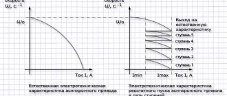
Note: The response of DC motors is usually not linear, so the actual rotation speed will not necessarily be proportional to the speed you specified during programming.
run(cmd)
Sets the operating mode of the motor.
Options:
- cmd - desired motor operating mode
Values that the cmd argument can take:
- FORWARD - forward rotation (the actual direction of rotation of the rotor will depend on the motor connection);
- BACKWARD — rotation “backward” (rotation in the opposite direction relative to FORWARD);
- RELEASE - stopping the motor. Stopping motor power. Equivalent to setSpeed(0). The motor shield does not have dynamic stopping mechanisms, so it will take some time for the motor to finally stop the rotor.
Example:
motor.run(FORWARD);
delay(1000); // rotates “forward” for 1 second
motor.run(RELEASE);
delay(100); // 'release the rotor' for 1/10 of a second
motor.run(BACKWARDS); // rotate in the opposite direction