Introduction
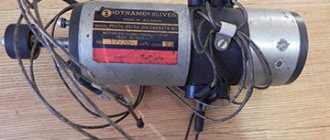
A DC electric machine is one of the easiest to operate, which is why it is so often used in radio electronics and robotics devices. This popularity is due to the simplicity of power supply and control - for this, two poles are supplied from an emf source (negative and positive), and when current flows through the windings, the shaft rotates. When the polarity changes, the motor performs reverse movement.
In radio electronics systems, such methods of controlling engine operation are called pulse width modulation (PWM). This process is characterized by a change in the duration of the applied voltage or the shape of its signal.
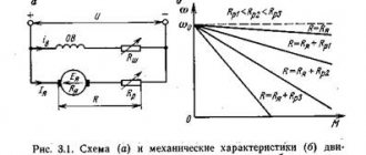
How can you change the rotation speed using PWM?
Using the PWM method, you alternately supply and cut off voltage to the motor windings at a high frequency. The pulse frequency can reach several kilohertz.
The amount of average voltage supplied to the motor directly depends on the shape of the PWM signal. The shape of the signal, in turn, is determined by the duty cycle, which can be represented as the ratio of the time the signal is applied to the total period (the sum of the time the voltage is applied and turned off). The result is a dimensionless value, which is expressed as a percentage - how much time out of the total period the voltage was supplied to the engine. In low current systems of 5, 12, 24 or 36 V, a cycle of 25%, 50%, 75% and 100% is applied.
Pulse width modulation
Motor control using Arduino and generated PWM signal
To start the process, the board generates a signal that is fed to the motor windings. To control the magnitude of the supplied signal, a transistor is included in the operating circuit. Which is connected to a break in the supply network, and a control pulse from Arduino is supplied to its base. By setting certain operating parameters with a set of commands for Arduino, the transistor will go into an open, closed or slightly open state.
In the picture below you can see an example of a circuit in which the power to the motor is controlled by the Arduino through a transistor. As you can see, here a signal is supplied from the PWM output to the base of the transistor, and voltage will be supplied to the winding through its collector and emitter.
Schematic diagram of dc motor control
Arduino programming can be done using a computer; both special utilities and classical programming languages are used for this. When programming the device, you can use a standard set of commands, which will provide access to the most simple commands. Or collect them in combination to form a specific logic for the operation of the device.
You can download an example of software commands for the operation of the above Arduino connection circuit from the link below. Using them, you can control the rotation speed, gradually increasing it to the maximum value, and also smoothly reducing it to a complete stop.
Full sketch of the project:
DC Motor Control with Arduino Uno
Commands used:
- void setup – field for setting the working output from the PWM port;
- void loop – field for creating a workflow;
- motorSpeed – sets the engine rotation speed;
- analogWrite – specifies the operation of a specific board pin;
- delay – sets the value of the time interval.
With the help of this program and the above diagram, you can easily change the rotation speed of a DC motor, but changing the direction of its rotation will be quite difficult. Since it will be necessary to change the direction of the flow of electric current through the windings. Therefore, it is much more convenient to change the direction of rotation using an H-bridge on semiconductor converters.
Connecting to Arduino
Economical connection of one motor without speed adjustment
To do this, close the jumper as shown in the figure, thereby connecting the EN pin to +5V
As mentioned earlier, with this method we cannot regulate the rotation speed, however, to control one channel of the module, two digital pins will be used instead of three.
Let's make the motor rotate “to the right” for 4 seconds, stop for 0.5 seconds, rotate “to the left” for 4 seconds, stop for 5 seconds and repeat the cycle again.
Sample code
// Tested on Arduino IDE 1.0.5 int IN3 = 5; // Input3 is connected to pin 5 int IN4 = 4; void setup () { pinMode(IN4, OUTPUT); pinMode(IN3, OUTPUT); } void loop () { // Opposite signals are applied to a pair of “IN” pins, the motor rotates digitalWrite (IN4, HIGH); digitalWrite(IN3, LOW); delay(4000); // Signals of the same name are applied to a pair of “IN” pins, the motor does not rotate digitalWrite (IN4, LOW); delay(500); // Different (and already opposite relative to the first case) signals are applied to a pair of “IN” pins, the motor rotates // relative to the first case) signals, the motor rotates in the other direction digitalWrite (IN3, HIGH); delay(4000); // Signals of the same name appear on the “IN” pins again, the motor does not rotate digitalWrite (IN3, LOW); delay(5000); }
Connection of one motor with speed control
In this example, we connected the ENB to the PWM pin (D3). Now it becomes possible to control the speed of the motor by changing the duty cycle of the sent PWM signal.
The duty cycle values are specified by the analogWrite(pin, number) function, where the number varies from 0 to 255, directly proportional to the signal duty cycle. For clarity, four values have been selected at which the engine starts at low speeds, reaches medium speeds, reaches maximum speeds and does not rotate.
Sample code
// Tested on Arduino IDE 1.0.5 int IN3 = 5; // Input3 is connected to pin 5 int IN4 = 4; int ENB = 3; void setup () { pinMode(ENB, OUTPUT); pinMode(IN3, OUTPUT); pinMode(IN4, OUTPUT); } void loop () { // Different signals are applied to a pair of “IN” pins, the motor is ready to rotate digitalWrite (IN3, HIGH); digitalWrite(IN4, LOW); // apply a PWM control signal to the ENB pin analogWrite(ENB,55); delay(2000); analogWrite(ENB,105); delay(2000); analogWrite(ENB,255); delay(2000); // Stop the motor by sending a low level signal to the ENB pin. // The state of the “IN” pins does not matter. analogWrite(ENB,0); delay(5000); }
Final example. Connection of two motors with variable speed control
In the sketch below, two motors will rotate in both directions with a smooth increase in speed.
Sample code
// Tested on Arduino IDE 1.0.5 int IN1 = 5; // Input1 is connected to pin 5 int IN2 = 4; int IN3 = 3; int IN4 = 2; int ENA = 9; int ENB = 3; int i; void setup () { pinMode(EN1, OUTPUT); pinMode(IN1, OUTPUT); pinMode(IN2, OUTPUT); pinMode(EN2, OUTPUT); pinMode(IN4, OUTPUT); pinMode(IN3, OUTPUT); } void loop () { digitalWrite(IN2, HIGH); digitalWrite(IN1, LOW); digitalWrite(IN4, HIGH); digitalWrite(IN3, LOW); for (i = 50; i <= 180; ++i) { analogWrite(EN1, i); analogWrite(EN2, i); delay(30); } analogWrite(EN1, 0); analogWrite(EN2, 0); delay(500); digitalWrite(IN1, HIGH); digitalWrite(IN2, LOW); digitalWrite(IN3, HIGH); digitalWrite(IN4, LOW); for (i = 50; i <= 180; ++i) { analogWrite(EN1, i); analogWrite(EN2, i); delay(30); } analogWrite(EN1, 0); analogWrite(EN2, 0); delay(8000); }
DC motor control using H-bridge
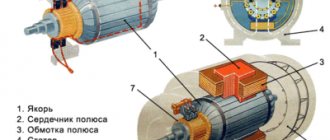
If we consider the principle of operation, then the H-bridge is a logical circuit of four logical elements (relay or semiconductor type), capable of switching to two states (open and closed). This example considers a bridge assembled on semiconductors. By simply changing the pairwise state of these elements, the motor will rotate in one direction or the other without the need to switch its contacts.
This device received its name due to its external resemblance to the letter “H”, where each pair of transistors is located in the vertical elements of the letter, and the directly controlled motor itself is located in the horizontal. An example of an elementary H-bridge of four transistors is shown in the figure below. By opening and closing the desired circuit elements in pairs, you can pass current through the windings in opposite directions.
H-bridge circuit
Look at the figure, in this circuit the motor power is controlled from terminals A and B, to which the control potential is applied.
The principle for determining the direction of rotation in an H-bridge is as follows:
- when a pulse is applied to the bases of transistors Q1 and Q4 to open the transition, current flows through the motor windings in one direction;
- when a pulse is applied to the bases of transistors Q2 and Q3 to open the transition, the current will flow in the opposite direction compared to the previous one and a reverse movement will occur;
- pairwise opening of transistors Q1 and Q3, Q2 and Q4 leads to braking of the rotor;
- opening transistors in the sequence Q1 and Q2 or Q3 and Q4 is completely unacceptable, since it will lead to a short circuit in the circuit.
By using an H-bridge circuit to control the operation of a DC motor, you can implement a complete set of operations for an electrical machine without the need to reconnect its terminals. Due to the complexity of selecting transistors and connecting them to an H-bridge circuit, it is much easier to use existing drivers that have this function. Among them, the most popular are the L293D and L298N drivers.
Comparing both drivers, it should be noted that the L298N is superior to the L293D both in terms of performance and available options. Despite the fact that the L293D is a cheaper model, the L298N, due to significant advantages, has begun to be used much more often. Therefore, in this example we will look at the principle of motor control using the L298N driver and Arduino board.
What is the L298N driver?
This board contains a microcircuit and 15 outputs for generating control signals. Designed to transmit signals to inductive-type working elements - motor windings, relay coils, etc. Structurally, the L298N allows you to connect up to two such elements; for example, you can simultaneously control two stepper motors through it.
The diagram below shows an example of the distribution of L298N pins from a working chip.
L298N. conclusions
- Vss – power output for logic circuits at 5V;
- GND – zero pin (aka body);
- INPUT1, INPUT 2, INPUT 3, INPUT 4 – allow you to smoothly increase and decrease the engine rotation speed;
- OUTPUT1, OUTPUT2 – terminals for powering the first inductive load;
- OUTPUT3, OUTPUT4 – terminals for powering the second inductive load;
- Vs – output for switching power;
- ENABLE A, B – pins, with the help of which the channels are separately controlled, can set active and passive modes (with adjustable rotation speed and with set one);
- CURRENT SENSING A, B – pins for setting the current mode.
Motor driver RKP-01A-V2 two-channel L298N
Two-channel motor driver RKP-MDL298-01A-V2 on the L298N chip.
It can be used to control the rotation of two independent brushed direct current motors (DC motors) or one two-winding four-wire stepper motor.
Here you can see a detailed article about connecting the motor driver on the L298N chip to Arduino =>>
Motor driver RKP-01A-V2 thanks to the L298N motor driver chip allows you to easily control two electric motors using power from 5V to 35V. The cooling radiator installed on the main L298N chip allows it to withstand a load current of up to 2A per channel. To protect the motor driver from overload, special Shotki Diodes are used. The motor controller module allows you to use it in a variety of robotics projects, placing it as you wish.
View DataSheet of L298N motor driver chip (PDF format size 611 KB)
The key features of the RKP-01A-V2 motor driver are the presence of an L298N cooling radiator, small dimensions and weight (35 grams), as well as LED indication of the presence of power and indicating the direction of rotation of the motors.
Characteristics of the motor driver RKP-01A-V2 on the L298N chip: - Driver chip: L298N (with cooling radiator) - Possibility of powering external logic (Vss): +5V ~ +7V (internal stabilizer +5V) - Input voltage of the logic part (Vd) : 6V to 12V - Input voltage of controlled part (Vs): +5V to +35V - Operating current of external logic part (Iss): 0 ~ 36mA - Load current of each controlled part (Io): 2A - Peak load current of each controlled part parts (Io): 3A - Maximum power consumption: 20W (at temperature = 75°C) - High input control signal level (High): 2.3V = Vin = Vss - Low input control signal level (Low): -0.3V = Vin = 1.5V — Operating ambient temperature: from -25 to +130°C — Dimensions of the module with mounting posts and radiator L298: 53 x 47 x 27 mm — Weight of RKP-01A motor driver: 35 grams
The motor controller board has four special holes and special mounting posts made of brass.
The RKP-01A expansion board can be used together with Arduino and is installed separately from the Arduino processor module. It is used, for example, to build moving robots on a wheeled or tracked drive.
To connect direct current motors (DC motors), the following ports are used: OUT1 and OUT2 - motor A OUT3 and OUT4 - motor B (electric motor control is completely independent of each other)
To operate, connect the power source to the “VCC” contact of the triple terminal block. When power is supplied from +6V to +12V and jumper JP1 is on, power is supplied to the stabilizer, which outputs +5V to power the driver logic. There is no need to supply +5V power separately for logic. When supplying power above +12V , jumper JP1 must be removed. Power is supplied to the logic separately via the “+5V” terminal.
DC motors are controlled through special inputs: ENA (ENB) – a connected jumper activates the motor control channel. ENA (ENB) - connect to the PWM output of the MCU, to control the rotation speed I1 (I3) and I2 (I4) - logical inputs (have switchable pull-up resistors) for setting the direction of rotation (see table below)
ENA I1 I2 Motor A state PWM>0 0 0 Stop PWM>0 0 1 Clockwise rotation PWM>0 1 0 Counterclockwise rotation PWM>0 1 1 Stop ENB I3 I4 Motor B state PWM>0 0 0 Stop PWM>0 0 1 Clockwise rotation PWM>0 1 0 Counterclockwise rotation PWM>0 1 1 Stop
The stepper motor control logic is as follows: A, B, C, D, these are the four windings of the stepper motor. Diagram below (four phases of stepper motor).
The stepper motor is controlled in the same way as two DC motors.
The principle of motor control using Arduino and the L298N driver
Thanks to the presence of a built-in bridge in the L298N driver, this board allows simultaneous control of two electrical machines from two pairs of outputs. The logic circuit in this device operates on a voltage of 5V, and the electrical machines themselves can be powered up to 45V inclusive. The maximum permissible current for one channel of the board is 2A.
As a rule, this driver has a modular design, due to which the module kit already includes the working elements, pins and connectors necessary for transmitting control signals. An example of such a driver is shown in the figure below:
L298N driver example
Now let's look at how the motor is controlled using the L298N driver. The motor is connected to screw terminals - a pair to power each motor. The remaining terminals are designed to supply plus and minus power, as well as to receive a reduced voltage (they supply a certain level of supply voltage from which the motors operate, and the internal converter lowers it to 5V for its own logic circuits). The plug-in terminals of the board perform pulse-width modulation when generating operating signals.
Clamps where to connect the motors
It should be noted that the terminal clamp with three pins not only supplies the supply voltage to the board, but also allows you to obtain it, already converted for the driver’s own needs, with a value of 5V, as shown in the figure above. This output can be used to power the same Arduino or any other devices that are powered by 5V.
An important point in obtaining 5V from this terminal pin is the installation of a black jumper, which is responsible for converting a voltage level other than 5V, provided that its level is below 12V. If the supply voltage level is higher than 12V, the jumper must be removed, since the internal converter is not designed for it, and the board itself must be powered from 5V through the third pin of the same terminal block.
Connecting the L298N module
GND - ground. Clamps where to connect the motors It should be noted that the terminal clamp with three pins not only supplies the supply voltage to the board, but also allows you to receive it, already converted for the driver’s own needs, with a value of 5V, as shown in the figure above.
You can stop their rotation by applying a LOW signal to the same pins indicated above. The diagram below shows an example of the distribution of LN pins from the working chip.
HIGH time. We used a tank platform, given that the motor turns the gearbox and tracks, it requires a decent amount of current to start it.
In the sketch below, two motors will rotate in both directions with a smooth increase in speed. Connection diagram The motor supply voltage is below 12 volts, which means jumper 3 is installed, jumpers 1 and 2 on the ENA and ENB contacts are removed.
Not so long ago we looked at the algorithm for assembling a CNC with our own hands, where we touched upon the topic of controlling stepper motors, because they allow you to simply and accurately position the cutter at a given point. Due to the complexity of selecting transistors and connecting them to an H-bridge circuit, it is much easier to use existing drivers that have this function. All this will lead to rotation of the motor in a certain direction. Terminal block 3 is responsible for connecting the power supply to the motors.
Connecting L298N to Arduino board
Moreover, some pins must support PWM modulation. At the same time, it is possible to change the speed and direction of rotation of the motors. This example considers a bridge assembled on semiconductors.
Otherwise, when specifying a movement, for example, clockwise, one of them will rotate in the opposite direction. Connecting a bipolar stepper motor to module L for control via Raspberry Pi.
HIGH wait 5 seconds. Types of stepper motors: bipolar, unipolar, with four windings. STEPPER MOTOR SIMPLE DRIVER FOR IT