As you know, a common cause of short circuits and sparks is the engine commutator unit. Due to the short service life of the brushes, an emergency situation may occur.
Therefore, experts have developed an engine with a brushless operating principle, which eliminates the occurrence of dozens of problems due to the absence of a collector unit.
We will learn more about it, its design and operating principle from this article.
Brushless Drive Terminology
The DC electric motor of a brushless unit has a name – brushless. The internal device that changes the flow of current in the winding is called a driver or generator of periodic voltage changes, in other words, an inverter.
The drivers are always fixedly fixed on the stator. At the same time, a network switch or network switch is equipped with semiconductor triodes, of which there are six in total.
It is they who direct the current voltage to certain turns of the electric motor wire.
In narrow-profile publications for electromechanics, the brushless type of motor is called valve-type, because transistors are otherwise called valves.
In addition, devices are divided into several types depending on design and electromotive force.
In American sources, one type of electric motor is marked with the letters BLDC, which is an abbreviation of a term that literally translates as “brushless DC motor.”
It is in this type that EMF occurs according to a trapezoidal diagram. In another type, which is marked with the abbreviation PMSM, an EMF occurs in a sinusoidal pattern.
Advantages of brushless motors
Brushless motors have a number of advantages, which have determined their areas of application. They have better performance. Their torque is much higher compared to conventional engines. Brushless designs have higher dynamic characteristics and efficiency.
Among other advantages, it should be noted silent operation, increased service life and higher rotation speed. The motor size to torque ratio is higher than other types. This is especially important in areas where size and weight are critical factors.
The design of a brushless electric motor and its operating principle
As we discussed above, a brushless electric motor is not equipped with a commutator unit. Its function is performed by a network switch based on semiconductor triodes.
It is the radio-electronic component that switches the turns of the wire of the fixed base of the engine, during which a magnetic field of active rotation simultaneously arises, which begins to interact with the field of the device shaft.
At the moment an electric current flows through an object conducting current in the magnetic field zone, the force Am presses on it, due to which a rotating moment arises on the rotor of the electric motor.
The entire principle of operation of a brushless motor is based on such simple work.
First of all, three turns of wires are most often placed on the stationary base of a brushless motor, according to the same principle as the three-phase cores in AC motors, which is why they are sometimes called 3-phase, although this term is only partially suitable.
BLDC motors (abbreviation for brushless motor) are often powered by a constant supply of electrical current, such as a battery, but the starter switch constantly alternates the flow of voltage through the turns of wires.
The final result of the current voltage that is supplied to the turns is formed by the control signals of semiconductor triodes in a “rectangle” pattern.
The so-called 3-phase brushless drive can be equipped with either three wires, or four if the type of wire wrapping is “star”.
The turns of copper cores are located in the so-called “notches” of the base of the stationary element of the device.
Due to the fact that brushless motor designs may differ, just like their purpose, the number of turns of wires, coils or windings, which mean the same thing, may differ. There are also several coil patterns.
Depending on the chosen scheme, the coils in each notch live, they can be connected alternately or opposite each other. There is also a similar option as for DPT in the “star” or “triangle” pattern.
As we wrote above, it all depends on the goal set for a particular device.
We recommend viewing the pictures below.
In addition, the fixed base, or stator, can be equipped with automatic shaft position sensors. Often, well-known and widespread Hall magnetic microcomponents are used, which are used in household appliances, for example, washing machines.
They are the ones who can give the corresponding signal pulse to the controlling switch, under the influence of the magnetic field of the shaft.
This process is extremely important because the switch needs to timely change the power supply to the desired turns of the coil wires. Thanks to this, the electric motor will work as efficiently as possible without wasting resources.
Most often, three sensors are installed on one brushless drive, which is quite enough. However, their presence complicates the design a little, but for many specialists, connecting a couple of additional cables for power will not be difficult.
In addition, to activate the operation of the electric motor, magnets are always mounted on the shaft, and to stop them - on a stationary element.
As you probably know, in engines with commutator units the principle is exactly the opposite; it is important not to confuse this point and pay enough attention to it.
The magnetic elements themselves are mounted in alternating positive charges, but this does not mean that the number of elements is directly proportional to the number of positive charges.
Several elements can form one positive charge. As is the case with other electric motors, the amount of positive charge is equal to the number of shaft rotations per minute.
Operating principle and design of a brushless motor
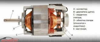
Like other motors, a brushless motor consists of two main parts - the rotor (the moving part) and the stator (the stationary part). There is a three-phase winding on the stator. The rotor carries a permanent magnet, which can have one or more pairs of poles. When a three-phase voltage system is applied to the stator winding, the winding creates a rotating magnetic field. It interacts with the permanent magnet on the rotor and sets it in motion. As the rotor turns, its magnetic field vector rotates toward the stator's magnetic field. The control electronics monitor the direction that the rotor's magnetic field is taking and changes the voltages applied to the stator windings so that the magnetic field generated by the stator windings rotates ahead of the rotor's magnetic field. To determine the direction of the rotor's magnetic field, a rotor position sensor is used, since the magnet that creates this field is rigidly fixed to the rotor. The voltages on the windings of a brushless motor can be generated in various ways: simply switching the windings every 60° of rotation of the rotor or generating sinusoidal voltages using pulse-width modulation.
Types of brushless electric motors
As we described above, BDDCs can be divided into different types depending on the counter-electromotive force, the device design and the equipment with Hall sensors. The main two types, we have already discussed above, are BLDC - trapezoid circuit and PMSM - sine circuit.
For proper use, it is necessary to connect them to different sources of electricity, but in their practice, experts use them as similar devices with a single battery.
Depending on the design of the device, brushless motors are divided into the following types:
- Equipped with a rotating shaft inside. The most common option, which is often used in electrical devices with a high number of revolutions per minute.
- Equipped with external rotating shaft. This type is often used in devices in which it is necessary to capture rotating torque.
To choose one or another type of engine, you need to know for sure where it will be used.
At the moment, manufacturers produce numerous options for brushless motors, both with and without Hall sensors.
Experts say that although microcomponents are very useful for work and improve its quality, and can also perform several tasks, for example: powering the turns of wires, controlling position by electromotive force, sometimes you can do without them.
Main parameters of the BDTP:
- Duration of work, from maximum to minimum.
- Upper limit of operating current.
- The upper limit of the operating electrical voltage.
- The upper limit of the device power.
- Upper limit of rotations. On a note. The manufacturer may specify the number of rotations per volt of voltage without load on the rotor. To determine this parameter, it is necessary to multiply the indicated indicator by the upper limit of the operating voltage.
- Reverse force of core turns. The PD coefficient will be higher if this indicator is as low as possible.
- Seconds after which the current in the turns of the cores reaches its maximum value of the upper limit.
Advantages and disadvantages
High reliability due to the absence of a collector. This is the main difference between brushless motors and brushed motors. The brush-collector unit is a movable electrical contact and itself has low reliability and resistance to various environmental influences.
No need to maintain the collector unit. It is especially relevant for medium and large engines. For microelectric motors, repairs are not economically justified in all cases, so this point is not relevant for them.
Complex control scheme. A direct consequence of transferring the function of switching winding currents to an external commutator. If in the simplest case, to control a brushed motor you only need to have a power source, then for a brushless motor this approach does not work - a controller is needed even to solve the simplest motion control tasks. However, when it comes to solving complex cases (for example, positioning problems), the controller becomes necessary for all types of motors.
High rotation speed. In commutator motors, the speed of movement of the brush along the commutator is limited, although it varies for different designs of the two parts and different materials used. The maximum speed of movement of the brushes along the commutator greatly limits the rotation speed of the commutator motors. Brushless motors do not have such a limitation, which allows them to operate at speeds of up to several hundred thousand revolutions per minute - a figure unattainable for brushed motors.
High power density. The ability to achieve high power densities is a consequence of the high rotational speeds available for the brushless motor.
Good heat dissipation from the winding. The winding of brushless motors is fixedly mounted on the stator and it is possible to ensure good thermal contact with the housing, which transfers the heat generated in the motor to the environment. In a brushed motor, the winding is mounted on the rotor, and its thermal contact with the housing is much worse than in a brushless motor.
More wires to connect. When the engine is located close to the controller, this is certainly not a reason for grief. However, if the environmental conditions in which the engine operates are very complex, then moving the control electronics to a considerable distance (tens and hundreds of meters) from the engine is sometimes the only available option for system developers. Under such conditions, each additional circuit for connecting the motor will require additional cores in the cable, increasing its size and weight.
Reducing electromagnetic interference coming from the motor. The brush-collector contact creates quite strong interference during operation. The frequency of this interference depends on the engine speed, which makes it difficult to combat them. For a brushless motor, the only source of interference is the PWM of the power switches, the frequency of which is usually constant.
Presence of complex electronic components. Electronic components (Hall sensors, for example) are more vulnerable than other engine components to harsh environmental conditions, be it high temperature, low temperature or ionizing radiation. Brushed motors do not contain electronics and do not have this vulnerability.
Brushless Motor Connection and Schematic Demonstration
As we wrote above, for proper operation of the BLDC, you need a specialized device for switching voltage. To choose the right one, you need to take into account the current strength. Switching devices can be purchased as a set or separately. A device from foreign manufacturers may be called “Electrical Controller”.
The connection process itself is very simple and will not pose a problem even for a novice specialist. The main thing you should not forget is that to change the direction of revolutions, you need to switch two phase conductors at once, just like in other engines.
Also be sure to take a few minutes of your time to watch the informative video tutorials located at the end of this article.
DC motor without brushes. How it works?
In order to make the operation of devices more reliable, more efficient and less noisy, there has recently been a tendency to use brushless DC motors.
They are also lighter compared to brushed motors for the same power output. In conventional DC motors, the brushes wear out over time and can cause sparking. Therefore, a brushed motor should not be used where reliability and long service life are required. Let's see how a brushless DC motor works. The rotor of such an electric motor is equipped with permanent magnets. The stator has a coil arrangement as shown in the figure. By applying constant current to the coil, the coil will become an electromagnet. The operation of the motor is based on the interaction of magnetic fields between a permanent magnet and an electromagnet. In this state, when coil A is energized, the opposite poles of the rotor and stator attract each other. As soon as coil A approaches the rotor, voltage is applied to coil B. Coil B approaches the rotor and voltage is applied to coil C. After this, a voltage of reverse polarity is applied to coil A. This process is repeated and the rotor continues to rotate. A humorous analogy to understand the operation of an engine is to remember the story of the donkey and the carrot. The donkey tries to catch up with the carrots, but the food moves at the same time as him and remains out of reach. Even though this motor works, it has one drawback. As you can notice that at any given time only one coil is energized. Two inoperative coils will significantly reduce the engine's power output. But there is a trick that can overcome this problem. When the rotor is in this position along with the first coil, which is pulling the rotor, it is possible to excite the coil behind it in such a way that it will also push the rotor. At this moment, a current of the same polarity is passed through the second coil. The combined effect produces more torque and power from the engine. The combination of forces also ensures that the engine has a smooth and constant torque curve. With this configuration, the two coils must be switched separately, but by making a small modification to the stator winding this process can be simplified. Simply connect the free ends of the coil together. When power is applied to coils A and B, current will flow through them. The same as if we applied voltage separately. This is how it works, but you may have doubts: “How do I know which stator coil to apply voltage to?” “How to apply voltage to get continuous rotation from the rotor?” For this we use an electronic controller. Sensor A detects the position of the rotor and, based on this information, the controller decides which coils to apply voltage to. Most often, the Hall sensor effect is used for this purpose. So far we have discussed a design known as “external overclocking”. An "internal overclock" design is also available in the market. We hope you found some useful information. Thank you. _ Source
Scope of application of BLDC
BDTPs are widely used for small household appliances, audio, video devices, as well as PC and laptop components, such as hard drives, players, drives, batteries and batteries.
They are also used for gadgets and devices for entertainment and work, such as radio-controlled devices. Industrial machines and professional factory equipment cannot do without BDTP.
Brushless motors are required to equip the wheels of modern electrical equipment, such as scooters, motorcycles, bicycles and Segways. Eco-friendly new cars are no exception.
As you can see, the area of the BDTP is incredibly huge, since the absence of the collector itself allows the device to be used in places with an increased risk of emergency situations, too high humidity, and sudden temperature changes.
It has come to the point that BDTPs are used in space production, which cannot but please observers of technological progress.
Pros and cons of BC engines
Pros:
- Simplified motor design due to the exclusion of the commutator.
- Higher efficiency.
- Good cooling.
- BC engines can operate in water! However, do not forget that due to water, rust can form on the mechanical parts of the engine and it will break down after some time. To avoid such situations, it is recommended to treat engines with water-repellent lubricant.
- Lowest radio interference.
Minuses:
The only downside is the impossibility of using these engines without ESC (rotation speed controllers). This somewhat complicates the design and makes BC motors more expensive than commutator motors. However, if design complexity is a priority, then there are BC motors with built-in speed controllers.
Solving problems in TOE, OTC, Higher Mathematics, Physics, Programming...
CONTACTLESS DC MOTORS
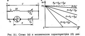
DC motors of conventional design have a valuable quality - the ability to widely and smoothly regulate the rotation speed. However, they have a significant drawback due to the brush-collector unit. It is quite natural that the idea arose to create motors that have the advantages of DC motors and are free from their disadvantages. Such motors are called non-contact DC motors.
Fig.5.1. Block diagram of a contactless DC motor
Contactless DC motors consist of three elements (Fig. 5.1):
1) a contactless motor with an m-phase winding on the stator and an excited rotor, usually in the form of a permanent magnet;
2) a rotor position sensor (RPS), made in the same housing with the motor and designed to generate control signals for the timing and sequence of current switching in the stator windings;
3) a switch, usually a transistor, which, using DPR signals, switches currents in the stator windings.
Operating principle
Let's consider a contactless motor using the example of a simplified diagram (Fig. 5.2). It consists of a motor with three windings on the stator, shifted in space by 120 degrees and connected in a star, a DPR with one signal element (SE) and three sensitive elements (SE) (their number is equal to the number of stator windings), a switch made on three transistors operating in switch mode, i.e. in "closed" or "open" mode.
Rice. 5.2. Simplified circuit diagram of a non-contact DC motor
In the position shown in Fig. 5.2, the signal element through the sensitive element “A” opens the transistor TA. Winding A carries current IA. The magnetizing force of the FA winding interacts with the flux of the rotor permanent magnet. A torque arises and the engine begins to rotate (1st stroke in Fig. 5.3). The DPR SE also turns together with the rotor. When the rotor is rotated at an angle slightly greater than 30°, the SE will act on two SEs at once: “A” and “B”. This means that two transistors will be open at once: TA and TV. The current will flow through both windings A and B. The resulting NS stator FAB will appear, which will rotate 60° compared to the first position (2nd cycle in Fig. 5.3).
Rice. 5.3. The first 3 strokes in the operation of a contactless DC motor
This NS continues to interact with the field of the permanent magnet; the engine continues to develop torque.
When the angle of rotation becomes slightly more than 90°, the transistor TA will close, the current will flow only through winding B. The rotor field will interact only with the NS of this winding, however, the torque will still act on the motor rotor and rotate it in the same direction (3 th cycle in Fig. 5.3). Ultimately, the engine will develop a speed at which its torque will be balanced by the load torque.
If a contactless motor had the same number of windings, sensitive elements and transistors as a conventional motor has collector plates, then in their properties and characteristics they would be no different from each other. However, an increase in the number of elements greatly complicates the design of the machine. Therefore, in real engines the number of windings, and, accordingly, the number of sensitive elements and transistors does not exceed 3-4.
The small number of windings determines a number of operating features of a contactless DC motor.
1. Torque ripple - occurs due to the abrupt movement of the stator NS (see positions 1,2,3 in Fig. 5.3). In accordance with the general laws of electromechanical energy conversion, the torque of a contactless motor can be defined as the scalar product of the rotor magnetic flux and the NS interacting stator windings
where T = L/r is the electromagnetic time constant.
The expression before the parenthesis is the armature current in the absence of inductance. Then
(5.4)
At high speeds, when the switching time is short, the current in the windings does not have time to reach a steady value. Its effective value becomes less than at L = 0
The torque is directly proportional to the armature current, therefore
| (5.5) |
or
(5.6)
Analysis of expression (5.6) shows that the moment has two components. The first is time-independent. It is equal to the torque in the absence of inductance. The second is a variable. It appears due to the inductance of the windings. This component has a negative value at all speeds (U > E). Therefore, it can be argued that, like the current, the torque of a brushless motor is less than the torque of a conventional brushed motor.
Substitute the value of EMF E = сenФ into formula (5.6), we obtain the mechanical characteristics of the contactless motor
(5.7)
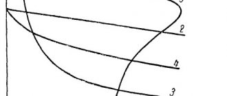
Let us express this characteristic in relative units, taking the starting torque (n = 0, U = Unom) as the base moment, and the idle speed (M = 0, U = Unom) as the base speed. Time t = ¥
Rice. 5.6. Mechanical characteristics of a contactless DC motor for different values of α and L: L2 > L1 > 0
Let us divide both sides of equation (5.7) by Mn:
(5.8)
Let us denote a = U/Unom. Taking n0 = U/(seF) into account, we obtain
(5.9)
where n = n/n0 is the relative speed of the motor.
In Fig. Figure 5.6 shows the mechanical characteristics of a contactless motor for different stator winding inductances L. It can be seen that as L increases, the nonlinearity of the characteristics increases.
The rotation speed of contactless motors can be adjusted over a wide range by changing the supply voltage.
However, in practice, the pulse method is more often used, the essence of which is to change not the value of the constantly supplied voltage, but the duration of the motor power supply with the rated voltage.
§ 5.1. Rotor position sensors
Rotor position sensors are determined by their sensing elements, which can be constructed using Hall EMF, photoelectric effect, etc.
Rice. 5.7. Transformer type rotor position sensor
Electromagnetic-transformer type sensors have become quite widespread. In Fig. 5.7. one of them is shown.
The sensitive elements of the sensor are three transformers (Tr1, Tr2, Tr3), shifted in space by 120 el. hail Transformer cores are made of quickly saturated materials - ferrite, permalloy, etc. The primary windings of the transformers (I) are supplied with high frequency voltage (of the order of several kilohertz) from a low-power source. The secondary windings are connected through diodes to the bases of the corresponding transistors.
The sensor rotor consists of a permanent magnet 1, a pole piece 2 made of soft magnetic material, and a non-magnetic half-cylinder 3.
The structural elements of the sensor are given such shapes and they are positioned so that the transformer cores, covered by the pole piece 2, are saturated. In this case, the EMF of the secondary windings of the transformers (II) is practically equal to zero and no signals are received at the bases of the transistors. Control signals come only from those transformers whose cores are not saturated.
Questions: 1) Draw a diagram of the NS stator windings (similar to positions 1,2,3 in Fig. 5.3) provided that the arc of the sensitive element is not 180°, but 120°.
2) What is the value of the total current consumed by the motor from the network at different angles of rotation of the rotor and a SE arc of 120°?
The concept of PWM frequency
When the keys are turned on, full load is applied to the engine. The unit reaches maximum speed. In order to control the motor, a power regulator must be provided. This is what pulse width modulation (PWM) does.
The required frequency of opening and closing keys is set. The voltage changes from zero to operating. To control the speed, it is necessary to superimpose a PWM signal on the key signals.
DC motor speed controller circuit for 12 volts
The PWM signal can be generated by the device onto several pins. Or create a PWM for a separate key using a program. The scheme becomes simpler. The PWM signal has 4–80 kilohertz.
Increasing the frequency leads to more transition processes, which produces heat. The height of the PWM frequency increases the number of transient processes, which causes losses on the switches. A low frequency does not provide the desired smoothness of control.
To reduce losses on the switches during transient processes, PWM signals are supplied to the upper or lower switches separately. Direct losses are calculated using the formula P=R*I2, where P is the loss power, R is the switch resistance, I is the current strength.
Less resistance minimizes losses and increases efficiency.