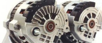
Rewind motor
Let's consider the process of rewinding brushless motors.
1. First of all, you need to remove the key from the shaft, you can see how it looks in the picture located just below.
For convenience, I recommend using two needles as they make it easier to push the ends of the dowel apart. Some people recommend small scissors, but for me it’s more difficult to catch the ends with them and they easily slide off the scissors.
2. Next, we remove the stator, if it does not come off, do not be afraid to pull it harder, there is nothing holding it there except powerful magnets.
3. Now the most difficult thing, in my opinion, is removing the lower part of the motor housing from the stator. But with the help of a regular hairdryer, this problem can still be solved, you just need to heat up this lower part. Once the glue has melted or broken down, you can begin removal.
4. But here, due to the fact that the stator is installed very tightly, problems can arise, so take some kind of device like the one you see just below and squeeze out the stator.
5. The stator has been removed and now you need to start removing the old winding; I don’t think it’s worth explaining in detail how to do this. Basically, cut off three thick wires and unwind the wire wrapped around the teeth.
6. So, after removing the old wire, you will need to wind a new one. To do this, we need to find or buy enameled wire with a diameter of 0.3 millimeters. It is usually sold in radio parts stores and so on.
7. Take a spool of wire and measure out 6 pieces 50 centimeters long (we do the same thing 2 more times since we have three phases).
8. You need to wind according to the pattern, as shown in the picture below. By the way, you can number the cloves so you don’t get confused. For each tooth you will get approximately 4 turns.
9. Next you need to install the stator in its place, use epoxy resin for this. After the resin has dried, you will need to solder the three wires that you cut at the beginning of the process. After that we assemble the motor.
10. Now all you have to do is check; to do this, connect the motor to the regulator as usual and check. If it spins normally and the traction is decent, then you have completed the task.
As you can see, in this way you can bring back to life any brushless motor that has burned out from overloads and thereby save money.
Source
About rewinding aircraft model engines
This section will present the main methods of rewinding brushless motors using the example of a motor from a CD drive and other motors.
First you need to remove the factory winding, trying not to damage the stator varnish and count the number of turns per tooth and connection diagram. But if the windings are varnished and do not move in any way, you should heat the stator to 200-300 degrees and try to remove them. If you just need to restore the engine and you are not going to change the characteristics of the engine, just rewind it in the same way as it was from the factory. The winding diagram has not been preserved or you want to change the characteristics of the motor, then read.
Each configuration offers slightly different properties and affects motor power. However, engine manufacturers have not yet decided which design is the best option. The diagrams below show the wiring diagrams for these connections.
After these pictures, it’s immediately clear why these schemes are called that way.
Typically, the Delta connection is chosen if you want a high-revving motor and the Star connection is used to obtain lower engine speeds and allow the use of larger propellers.
If we consider a Triangle connection and apply voltage to the two terminals, current will flow in all windings. To demonstrate how the current is distributed between the windings, assume that the resistance of one phase is 1 ohm. In this case, we have phase A of 1 ohm, connected in parallel with 2 other phases B and C (B and C are connected in series) with a resistance of 2 ohms. According to Ohm's law, it can be calculated that 2/3 of the total current will go through phase A and the remaining 1/3 will go through phases B and C. The resulting resistance that the controller will see will be 0.66 Ohms.
If we connect the terminals according to the Star circuit, then all the current will always flow through 2 phases at any given time. The resulting resistance for the regulator will be 2 ohms.
If we load the motor with a voltage of 10V, we will get a current of about 15A with a Delta connection and only 5A with a Star connection. It must be said that the triangle connection in this case gives more power. Also, we will get large currents, but the force to turn the large screw may not be enough. You can apply more voltage to the motor and still make this screw spin, but it is possible that this will cause the motor to burn out again.
As an example: Let's say we have a hard drive engine and we want to get the necessary thrust from it for a 72″ Piper Cub airplane. To ensure that the motor can withstand high currents, we will use a 0.6 mm wire. After some torture, it became clear that it was impossible to wind more than 10-11 turns with this wire. First, I connected it with a star (because I wanted to get more torque). Using 3 LiPo banks, with the propeller I needed, I managed to get a current of only 10A. The engine power was clearly not enough and I wanted to get more. The motor was reconfigured for a Triangle design, which gave more power. More thrust for flight, but at the same time high enough currents to burn out the motor.
What to do in this situation?
Source
Rewinding a “non-rewinding” auto-model brushless motor
Preface. Initially, I didn’t even believe in the success of my plan, and I started rewinding simply out of interest, and maybe even passion. I took the photo more out of habit, left over from the time I owned the “crazy” Sony Ericsson phone. Well, yes. Of course, the K750 model...))) It was done almost at random, using an impromptu method, so you should not consider my note as a guide to action. Consider that I simply proved that this is not only possible, but even quite simple.
Background. I have two engines lying around, namely the CMS-9000 from Castle Creations. Good, solid engines, it would seem, use them and be happy. Oh, no. The index speaks for itself. 9000 rpm is a bit too much for me. I simply have nowhere to put them. Even for drifting this is a lot. And given that I am now assembling a touring model for a child, and initially riding around the house is planned, then the consequences of installing a castle on the model are quite predictable. Searches for rewinding precisely these types of windings did not lead to success, at least on Russian-language resources. Aircraft or with a rotating rotor - please, many places, and extremely chewed. But I still decided to rewind them, since a couple of articles on rewinding recently appeared, for example from the respected Rustem Usmanov, with whom we crossed paths back in the threads of the rcdesign resource. Actually, it was this article that became the impetus for the transition from unhurried reflection to immediate action. For which I thank him very much!
Let's begin. Fewer letters - more information.
There was a patient - the Castle CMS-9000 brushless motor. 2T 9000 rpm. Very fast and very powerful (the 60A regulator heated up with it faster than you can read this sentence))). Powered exclusively by 2 cans of lipo. Three makes a pyromaniac's dream)). I wanted to rewind it in order to reduce current consumption and reduce the maximum speed by 2, maybe even 3 times (why - read the background).
You needed: 1. Enameled copper wire with a diameter of 0.3 mm 2. Wide masking tape 3. Wide transparent tape 4. Thin cardboard 5. Epoxy resin (glue) 6. Tools - stationery, for soldering, and metalworking tools for opening the motor.
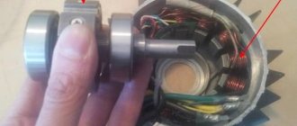
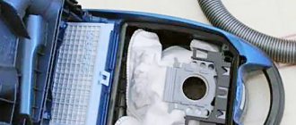
Opening the motor. I had to tinker. The cover on the shaft output side (front) was fastened with 3 hexagon bolts. There were no problems with her. I took out the rotor (in addition to the bearings, it has two brass rings - spacers), it is advisable to remove them immediately so as not to get lost.
Due to the poor review, at first I even hoped that the winding was on the stator, as for example in the photo below from another article, but removing the back cover killed these hopes completely...)))
The cover on the wire exit side was fastened with 3 small countersunk hex bolts. Having tried everything available, I realized that I don’t have this, although the set is very worthy. The size is somewhere around 1.1-1.15mm. Perhaps it was specially made non-standard so as not to be opened.
P.S. I opened the S3650-3980 engine, there the back cover is secured with three bolts for a Phillips screwdriver. But the lid is attached mainly by some kind of glue. At one time I simply loosened it, but people recommend first warming it up a little with a hairdryer to 200-250C.
Somehow I unscrewed one bolt. The other two had to be drilled out. The bolts are extremely hardened. The sharp drills with a diameter of 2-2.5 mm ran out after the first bolt.))) the second one had to be simply broken with pliers/the body bent slightly. I opened it and looked.
Wiring diagram of wheel motor
Wiring diagram for connecting the motor-wheel [2011-05-26]
The wheel motor package includes: brake handles with microswitches, gas handle, assist system sensor
controller and universal charger designed to charge both lithium-ion. and lead acid batteries:
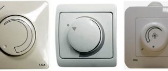
Controller pinout diagram :
There are several options for connecting the motor-wheel. One of the options in the diagram below.
The speed control knob is usually wired - the red wire is the +5V sensor power supply, the blue wire is ground, the green wire is the output signal. The voltage should change on green (relative to blue) from 1 to 3V (approximately) when you turn the knob. There is not a pure Hall sensor there, but a microcircuit with a Hall sensor. 4mA is the current consumption, and the voltage can be supplied from 4 to 10V. and output 2.5.V. Depending on the direction of the magnetic field, this voltage either decreases or increases as the intensity increases.
Connecting the electric motor to the controller: Three thick wires, yellow, green, blue - three phases (“A”, “B”, “C”). A harness of five thin wires: red - +5V, black “-” and three sensors - yellow, green, blue (“A”, “B”, “C”).
Tags: wheel motor Volyn, wheel motor Volyn, buy motor wheel in Ukraine Volyn, bicycle wheel motor Volyn
Motor Wheel Shkondin.
Many people talk and write about the Shkondin Motor Wheel. And often this happens at the level of myths and assumptions. Like, there is such an invention, and in many respects it is simply wonderful, but almost no one has explained how it works. Vasily Vasilyevich Shkondin himself refers everyone to his numerous domestic and foreign patents, where, supposedly, everything is written, and if you want to produce such wheels, then take licenses.
You can find a number of interesting articles about the Shkondin Motor Wheel on the Internet. For example, “Vasily Shkondin is the designer of the world’s best electric bicycles.” Or get information about the Shkondin engine from a number of films.
For example, by address. where you can watch 25 films at once. The same films can be found on the Internet at other addresses. I will cite just one of the latest films created by Starukhin.
To understand the features of the Shkondin wheel motor, or, more simply, the Shkondin motor, you need to compare its motor with the design of a standard DC motor and the so-called brushless motor. But first, let’s present some data from Shkondin’s patents, as well as a number of drawings that will allow you to understand the basic principles that Shkondin based his motor on.
You can get acquainted with Shkondin’s patents at the indicated addresses, but you can also read them on my website at the addresses here and here. Shkondin himself tries to position his engine as a motor-wheel, but if desired, this engine can be given any shape, while maintaining the very ideology of the invention. Let's take a closer look at the Shkodin wheel motor (Fig. 1)
Fig.1. Motor-Wheel Shkondina in a semi-disassembled state.
So, we have a stator inside and a rotor outside. There are 11 pairs of magnets installed on the stator at equal intervals, the poles of the magnets alternate. There are 22 poles in total. 6 U-shaped electromagnets are installed on the rotor, which, it turns out, have 12 poles. Brushes are installed on the rotor, with the help of which power is supplied to the electromagnets, and a collector is installed on the stator, from which electric current is supplied to the brushes. I draw your attention to the fact that the distance between the poles of any rotor electromagnet is equal to the distance between adjacent magnets on the stator. This means that at the moment of precise “contact” of the poles of one of the electromagnets with the neighboring poles of the magnets on the stator, the poles of the remaining electromagnets do not “contact” with the poles of the magnets on the stator.
The shift of the poles of the electromagnets on the rotor and the poles of the magnets on the stator relative to each other creates a gradient of magnetic field strength between them, and the latter is precisely the source of torque. For the Shkondin engine version shown in Fig. 1 it turns out. that at each moment of time, torque is created by 5 electromagnets out of 6. That electromagnet, the poles of which exactly “contact” the poles of the magnets on the stator, does not create torque. We get a kind of power efficiency of 83%. And this is in the absence of anti-EMF. And if we calculate the efficiency by the share of the magnets on the stator involved in creating thrust, then we find that out of 22 magnets, 20 magnets create thrust, i.e. 91%.
For now, I ask you to take my word for it that the Shkondin motor commutator is designed in such a way that at the right time it switches the direction of the current in the windings of the electromagnets, which provides thrust in only one direction. It can even be argued that this Shkodin motor uses 6 classic electric motors at once. The motor actually works as a motor, not a flywheel. This motor uses not only the power of the electromagnetic field, but also the commutator-brush mechanism to its full potential. And yet the engine is surprisingly simple. It consists of only 5-6 main parts. By creating precise dies for these parts, millions of Shkondin engines can be produced.
Let's take a closer look at one of Shkondin's patents. This is a PULSE-INERTIA ELECTRIC MOTOR. Let us highlight a fairly large quotation from this patent, which contains the main distinguishing features of the Shkondin engine:
“The pulse-inertial electric motor, in accordance with the present invention, contains: a stator with a circular magnetic core, on which an even number of permanent magnets with the same pitch are fixed;
a rotor separated from the stator by an air gap and carrying an even number of electromagnets, which are located in pairs opposite each other;
a distribution manifold mounted on the stator housing and having conductive plates located along the circumference, connected in alternating polarity to a constant current source and separated by dielectric gaps;
current collectors installed with the possibility of contact with the collector plates, and each of the current collectors is connected to the same terminal of the windings of the corresponding electromagnets.
Each of the electromagnets has two coils with sequentially opposite winding directions, and the windings of the coils of adjacent electromagnets are connected in series, and the terminals of the windings of opposite electromagnets, not connected to current collectors, are connected to each other. The number of permanent stator magnets equal to n and the number of rotor electromagnets equal to m are selected so that they satisfy the relations:
n=10+4k, where k is an integer taking the values 0, 1, 2, 3, etc.
m=4+2L, where L is any integer that satisfies the condition 0<=L<=k.
The most commonly used ratios of the number of permanent magnets and electromagnets are as follows: n=10, m=4; n=14, m=6; n=18, m=4; n=22, m=4, 6, 8, 10; n=26, m=4, 6, 8, 10, 12, etc.
This ratio of the number of electromagnets and permanent magnets, their relative position and the used switching circuit of electromagnets ensures the resonance of currents flowing through the windings of diametrically opposed electromagnets,
and as a result, reduces voltage surges (power consumption) when starting and accelerating the electric motor and improves its dynamic characteristics. In addition, this design of the electric motor makes it possible to recover electricity as efficiently as possible due to the occurrence of back EMF at idle.
It is possible to virtually eliminate sparking on current collectors by selecting a suitable advance angle between the current collectors and the conductive plates of the commutator. Therefore, current collectors are usually installed on an electric motor with the ability to adjust their position relative to the commutator. The advance angle ranges from 0 to 8°.
The total number of turns in the windings of the coils of opposing electromagnets can be different. In this case, the resonance phenomena intensify if the difference in the number of turns is 1/2p of the total number of turns in one of the coils, where p = 2, 3, 4, 5, etc.
The present invention can be used for both a unidirectional rotation motor and a reversible motor, depending on the method of connecting the power supply. In the first case, the positive conductive plates of the distribution commutator are connected to the positive pole of the direct current source, and the negative conductive plates of the distribution commutator are closed to the motor housing.
In a reversible electric motor, the positive conductive plates of the distribution commutator are connected to the positive pole of the DC source, and the negative conductive plates of the distribution commutator are connected to the negative pole of the DC source and are insulated from the motor housing. To change the direction of rotation of the electric motor, the connection of the poles of the DC source is reversed.
Structurally, the electric motor can be designed so that the rotor is located on the outside of the stator or the rotor is located inside the stator.”
Here are some drawings from this patent that will allow us to better understand the operating principle of the Shkondin motor.
Fig.2. Shkondin engine diagram with a stator inside the rotor.
Fig.3. Diagram of the windings and brush assembly of the Shkondin engine.
Fig.4. Shkondin engine with a rotor inside the stator.
Let's look at the last picture. On it, the poles of the rotor electromagnets at the top and bottom coincide with the poles of the magnets on the stator. These electromagnets do not participate in the creation of traction, so no power is supplied to them. The poles of the electromagnets on the right and left do not coincide with the poles of the magnets on the stator. Therefore, power is supplied to these electromagnets. And it is these electromagnets that create torque. And this is exactly what energy from the battery is spent on.
Note that both the right and left electromagnets immediately interact with the magnetic fields of the three adjacent stator magnets. And this is a typical magnetic track, which, due to gradients in magnetic fields, allows you to obtain maximum thrust. If we count the thrust by the electromagnets involved, we find that 50% of the electromagnets create the thrust, and if we count the number of stator magnets involved, we find that 60% of the magnets are involved in creating the thrust. And this is already a big indicator. Those. and using this diagram as an example, we were convinced that the Shkondin wheel motor is a motor within a motor.
Now consider the circuit of a standard electric motor with magnetization of the stator windings, taken here (Fig. 5):
Rice. 5.Standard DC motor
This motor has only a couple of brushes, but the commutator has a mass of contacts, numerically equal to the number of conductors of the rotor winding. The upper right corner shows a cross section of the motor with an incorrect indication of the direction of currents in the conductors of the rotor winding. The fact is that at each moment of time, current is supplied only to a pair of conductors, which means that in only one conductor at the top the current flows away from us, and at the bottom only in one conductor does the current flow towards us. The remaining sections of the rotor of such a motor work like a flywheel, which is not always good. Therefore, when starting, due to the need to “move the rotor from its place,” such motors consume large current from the network or battery. Or, when turned off, such motors turn into generators, since stopping the rotor, which has high mechanical inertia, requires a long period of time.
Unfortunately, such motors make up the majority of DC motors in our industry. And replacing the stator electromagnets with strong permanent magnets will not change the weather.
Now let's look at the possibility of using the Shkondin engine in a brushless version. Shkondin himself received several patents, where as an option he considered the possibility of using his engine without a manifold. For example, the following figure (Fig. 6) shows the following diagram:
Rice. 6. Diagram of the Shkondin motor in a brushless version.
In this case, the Shkondin engine works approximately as shown in the following animation, taken from .
Rice. 7. Animation of the brushless motor
But there are significant differences. If in the engine in Fig. 7 the magnetic field rotates synchronously with the rotation of the rotor, causing the rotor to rotate following the rotation of the magnetic field, then in the Shkondin engine this is not the case. In the Shkondin engine, the “running” is the switching off of the rotor electromagnet current at the moment when the poles of the rotor electromagnet are installed opposite the poles of a pair of magnets on the stator. Moreover, at the moment the current in such an electromagnet is turned off, in other electromagnets the direction of the current changes to the opposite. This allows, at the right time or place, to replace the “attraction” of the poles of electromagnets to a pair of magnets on the stator with the “pushing” of the poles of electromagnets from a pair of poles of the stator magnets.
Therefore, Shkondin correctly makes the remark to his opponents that it is useless to approach his engine with generally accepted theories, that the windings of the rotor electromagnets cannot be connected either by a star or a triangle. It is true that the Shkondin engine is a set of magnetic tracks that dynamically change their parameters by switching the windings of electromagnets at the right time and in the right place. That’s why this motor produces results that ordinary motors could never dream of.
The Shkondin motor is not a flywheel, it is a device that, with high efficiency, uses the interaction of magnetic fields, the parameters of which skillfully change due to the correct relationship between the paired number of magnetic poles on the stator and the number of pairs of electromagnet poles on the rotor, the number of pairs of magnets on the stator is greater than the number pairs of poles of electromagnets on the rotor, a properly designed commutator or a synchronization device in a brushless version.
The Shkondin motor has, with the same mass and current supplied to the rotor windings, much more power than an electric motor of a standard design. The Shkondin motor can be structurally given any shape, both in the form of a wheel (pancake) and in the form of a cylinder, similar to the shape that is given to existing DC motors. This makes such engines suitable for installation in military equipment for a wide variety of purposes. These engines can be used in space. In aviation, such engines are well suited for helicopters, as they have low rotational inertia. This means that blades with such engines are easier to control and the likelihood of unforeseen disasters will be reduced.
In addition to the motor, Shkondin designed and assembled several versions of generators according to his own design. Moreover, both an engine and a generator can be installed on the same vehicle. And when the engine “pulls” the vehicle, the generator will generate electricity with an efficiency of more than 90% and return it to the battery. Shkondin's highest achievement is the creation of a twin engine and generator, which, supplemented by a small solar battery or windmill, practically becomes a “perpetual” engine, the power of which is sufficient to provide electricity to a rural house or apartment.
So it’s clear to me why the stroller for the disabled, assembled by Shkondin, runs the distance on a single battery
more than analogues collected in other countries. Or why a Shkondin electric bike can travel 50 kilometers or more on a pair of batteries for uninterruptible power supplies, which we are used to using for our computers. Or why the Shkondin wheel motor can be used to build a wind generator.
This article was written not as an advertisement for Shkondin, but as an attempt to understand the mechanism of its engine in order to slightly dispel the fog that has recently thickened over this invention. And it seems that the Shkondin engine, like all ingenious things, is a very simple device.
We can talk for a long time about the merits of the Shkondin engine. But until government officials or Russian business sharks show interest in this matter, the Shkondin wheel motor will remain a toy for a small group of enthusiasts. On the Internet one day I came across a small article that electric cars at the Winter Olympics in Sochi were created on the basis of Shkondin engines. I have hope and confidence that the Ministry of Defense of the Russian Federation will show interest in the Shkondin engine. And then we may become the owners of electric bicycles or electric vehicles in which Shkondin engines will be installed. And not only in wheels, but also in control systems.
Posted 02/15/2014.
Fuel-free energy
Motor-wheel of Vasily Vasilievich Shkondin
by Sunktor on Wed Jan 29, 2014 7:03 pm
Design
This motor-wheel, in my opinion, has a number of similarities with the John Searle generator.
Therefore, some of its principles are worth adopting.
V.V. Shkondin himself openly talks about the design of his wheel and has more than a hundred patents for different versions of its design, but he also honestly admits that he keeps the most important features of the design secret.
More details in this video:
I have been interested in the structure of its wheel for a long time, and several years ago I came across material that for some reason is not available now.
I saved it then and now you can read it:
While working on a dissertation at the Russian Language Institute. A.S. Pushkina, Shkondin V.V. I didn’t notice how the topic “Variation of lexical and grammatical units in the Russian language” (Russian as a foreign language - in comparison with German) grew into “Variation of technical units in relation to the functionality of various types of electrical machines in vehicles.”
Friedrich Engels's philosophical assumption that only then can something original and exceptional be achieved in scientific research when completely different areas of knowledge are united turned out to be correct.
Already at the first exhibition - the World Salon of Inventions "Brussels - Eureka - 1990" V.V. Shkondin became the man of the year in Belgium, and his pilot model of an electric wheelchair on the “Shkondin Motor Wheels” was awarded a gold medal and a special prize from the Belgian Minister of Finance.
For the first time in world practice, the payment of fees for an international patent application in 26 countries for the author was made by the State Committee for Inventions (application No. 4731991/07 dated 01.09.89).
After 18 months (generally accepted regulations), the expert of the European Patent Office notified the State Committee for Inventions and the author that “as a result of the examination, the above invention was not opposed to a single publication” (from Soyuzpatent letter No. 2412R dated July 23, 1992).
The pulse-inertia electric motor, in accordance with the present invention, contains:
a stator with a circular magnetic core on which an even number of permanent magnets with the same pitch are fixed; the number of permanent magnets is at least 2 more than the number of rotor electromagnet shoes;
a rotor separated from the stator by an air gap and carrying an even number of electromagnets, which are located in pairs opposite each other; a distributor mounted on the stator housing and having conductive plates located along the circumference, connected in alternating polarity to a constant current source and separated by dielectric gaps;
Each of the electromagnets has two coils with sequentially opposite winding directions, and the windings of the coils of adjacent electromagnets are connected in series, and the terminals of the windings of opposite electromagnets, not connected to current collectors, are connected to each other.
The number of permanent stator magnets equal to n and the number of rotor electromagnets equal to m are selected so that they satisfy the relations:
n=10+4k, where k is an integer taking the values 0.1, 2, 3, etc. m=4+2L, where L is any integer that satisfies the condition 0^L
The most commonly used ratios of the number of permanent magnets and electromagnets are as follows: n=10, m=4; n=14, t=6; n=18, t=4; n=22, t=4, 6, 8, 10; n=26, t=4, 6, 8, 10, 12, etc.
This ratio of the number of electromagnets and permanent magnets, their relative position and the used switching circuit of electromagnets is the coherence (multiplicity) that ensures the resonance of currents flowing through the windings of diametrically opposed electromagnets, and as a result, reduces voltage surges (power consumption) when starting and accelerating the electric motor and improves its dynamic characteristics.
In addition, this design of the electric motor makes it possible to recover electricity as efficiently as possible due to the occurrence of back-EMF not only at the moment of braking, but also during movement, which significantly increases the autonomous driving range of the vehicle.
The total number of turns in the windings of the coils of opposing electromagnets can be different.
In this case, the resonance phenomena intensify if the difference in the number of turns is 1/2p of the total number of turns in one of the coils, where p = 2, 3, 4, 5, etc.
The present invention can be used for both a unidirectional rotation motor and a reversible motor, depending on the method of connecting the power supply.
In the first case, the positive conductive plates of the distributor are connected to the positive pole of the direct current source, and the negative conductive plates of the distribution manifold are closed to the motor housing.
In a reversible electric motor, the positive conductive plates of the distributor are connected through an electronic speed controller to the positive pole of the direct current source.
The photograph shows an electric motor made in accordance with the present invention, which can be used as a wheel motor for various vehicles, such as an electric bicycle.
The electric motor contains a shell that acts as a protective casing and directly transmits rotation to the wheel.
The shell is connected through spokes to the wheel rim.
The stator of the electric motor is located inside the rotor.
The stator has a circular magnetic core on which an even number of permanent magnets with the same pitch and alternating polarity are fixed.
In this case there are sixteen of them.
The rotor is separated from the stator by an air gap.
The electromagnets are shifted by 120° relative to each other.
Each of these electromagnets has two coils with sequentially opposite winding directions (that is, if one of the coils is wound clockwise, then the other is counterclockwise).
The total number of permanent stator magnets - n, equal to ten and the number of electromagnets - m, equal to four, satisfy the following relations:
P=10+4K,
m=4+2L, where k=L=0.
The operating principle of the electric motor is based on the forces of electromagnetic attraction and repulsion that arise from the interaction of the rotor electromagnets and the stator permanent magnets.
When an electromagnet passes a position where its axis is located between the axes of permanent magnets, the coils of the electromagnet are energized in such a way that they create a magnetic pole opposite to the pole of the subsequent permanent magnet in the direction of rotation and the same as the pole of the previous permanent magnet.
Thus, the electromagnet is simultaneously repelled from the previous one and attracted to the subsequent permanent magnet.
When the electromagnet passes a position opposite the axis of the permanent magnet, it is de-energized, since the current collector is located opposite the dielectric gap.
The electromagnet passes through this position by inertia.
The advantages of this electric motor lie in the strictly defined ratio of the number of electromagnets and permanent magnets and their relative position, as well as in the switching circuit of the electromagnets used.
Such ratios of multiplicity (coherence) create ideal conditions for high torque.
Motor wheel Shkondin
This project is dedicated to the promotion of light vehicles using electric traction as a drive (additional or primary). This is what an electric bicycle is. An electric bicycle combines the advantages of a regular bicycle, and the installed electric bicycle motor/motor wheel allows you to cover long distances without significant physical effort and financial outlay. After all, 100 km of travel on an electric bike costs less than 1 UAH of electricity! At the same time, just like when riding a regular bicycle, you do not pollute the environment, maintaining the balance of the ecosystem.
Electric bicycle: why is it needed?
There are often situations in which there is a need for an easy, fast and economical method of transportation. Here is one of these: It’s spring outside, good weather. You need to be in another place 15 km away within half an hour, carrying 10-20 kg of luggage with you. Use a car? It’s possible, but in order to transport your person, you need to start and warm up the engine, add fuel, burn it, stand in a traffic jam (if you’re unlucky) - all this is a waste of time and money.
Then maybe public transport? It’s possible, but it doesn’t always go straight to its destination, and waiting at a stop and the prospect of not being able to fit into the cabin of a crowded minibus is a waste of time. But maybe a taxi? It is possible if it is economically justified in the given situation. Bike! An excellent idea, but if there is a long climb ahead, 5%-10%, it’s hard not to make it in half an hour. What to do in this case? The answer is obvious: improve the bicycle to meet the necessary needs, add an electric motor, and it will cope with the task without any problems.
And there are many such situations, each with their own. Everyone needs to go to work, to the country, to the store, to nature, and everyone chooses the appropriate transportation option for themselves. An electric bike complements these possibilities.
Complete obedience of the electric motor, instant response to the accelerator handle, smokelessness and excellent dynamics of the electric drive - all these are not the last arguments in favor of electric vehicles!
You have a bicycle and would like to upgrade it by equipping it with an electric motor. But how to choose the right option?
Determine for yourself the average travel distance per day and on what terrain your “iron horse” will be used. If your trips will not exceed 20-25 km, the total weight is less than 100 kg, and the terrain is mostly flat, then we recommend that you choose the “lightweight version of the Light (250 W) electronic dial.” It should be taken into account that the speed without the help of pedals will not exceed 25 km/h. If you plan to overcome steep climbs with the wind and long distances (more than 40 km) with luggage or a trailer, then the “powerful version of the Power (500 W) electronic set” is at your service. Also, 500 W motors are more reliable in operation compared to mini-motors, since due to their weight they hardly heat up under load.
It is necessary to take into account that a lightweight electrical set requires the installation of 2 12V batteries, a powerful one - 4. It is recommended that the battery capacity be at least 9 Ah. The type of battery must be selected based on your needs and available budget. These are gel acid, lithium-ion and LiFePO4. They differ in weight, current output, service life and, of course, cost. The most common are sealed acid AGM or gel batteries due to their unpretentiousness to charge and discharge, reasonable prices and fairly acceptable traction performance. But if you are still not satisfied with the weight and dimensions of the battery, then you should think about a LiFePO4 battery (A123). with the same charge capacity, the space occupied is 1.5 times less than that of a battery, and the weight is 2-3 times less. Such batteries, unlike gel ones, can deliver more power immediately without the need for subsequent rest and charge much faster. It’s not for nothing that LiFePO4 (or A123) is used in electric-powered aircraft and helicopter models. According to the A123 Systems company itself, their batteries can withstand more than 1000 full charge-discharge cycles with currents of 10C and are designed for a 10-year service life. This means that charging time is reduced and the e-bike can be made even lighter and longer-range (>80 km). As you can see, progress does not stand still. So with such technologies, soon a range of 200-400 km for an electric bicycle will not be a novelty!
To make your choice easier, you can look at the comparative parameters of electronic kits and batteries from different brands presented on our website and choose the option with the characteristics that are suitable and most important to you. Some are attracted by their speed, others by the dynamics of acceleration, others by the optimal configuration, others by their compactness, and others by the ease of rolling and the miniature size of the electric drive.
What is a wheel motor?
The wheel motor, also called the Shkondin motor, is a brushless hub motor, a valve motor mounted on the front
or
rear
fork, spoked to the required wheel size. By installing the drive on a regular bicycle, we get a hybrid vehicle: an electric bicycle (person + electric motor), in which the physical strength of the cyclist can be combined with the traction force of a high-torque electric motor.
An electric bike/electric bicycle is a bicycle with an electric motor with a power of 180 W or more, which helps the cyclist to easily overcome climbs and long distances, rationally distributing the load on the legs and without losing the functions of a regular bicycle.
An electric bike, like a bicycle, is environmentally friendly, maneuverable and almost silent. Having charged from a regular 220V outlet, it is again ready for a long run. Average speeds range from 25 to 40 km/h. The driving range of an electric bicycle can vary depending on the characteristics of the motor, battery, weather conditions, and terrain, and averages 40 km on a flat section of road in warm, windless weather.
The efficiency of the 500W motor-wheel, which is more than 85%, is approximately constant throughout the entire speed range, the torque is maximum at start, so there is no gearbox, gearbox, variator, belt or chain drive or rubbing parts subject to rapid wear. A smooth increase in speed is ensured by the throttle handle - a kind of rheostat, control and overload protection - by the controller, driving force - by traction batteries.
Sources: www.e-bike.com.ua, vitanar.narod.ru, searlmachine.2x2forum.com, 7masters.info
Next articles:
- Polaris 2000w wheel motor
- Motor wheel from China ebay