Website for electricians
| Degree of sparking (commutation class) of DC electrical machines | |
| Sparking degree (switching class) Characteristics of sparking degree | Commutator and brush condition |
| 1 No sparking (dark switching) | No blackening on the commutator or carbon deposits on the brushes |
| 1¼ Weak spot sparking under a small part of the brush | Same |
| 1½ Weak sparking under most of the brush | The appearance of traces of blackening on the commutator, which can be easily removed by wiping the surface of the commutator with gasoline, as well as traces of carbon deposits on the brushes |
| 2 Sparking under the entire edge of the brush. Allowed only for short-term load shocks and overloads | The appearance of traces of blackening on the commutator, which cannot be eliminated by wiping the surface of the commutator with gasoline, as well as traces of carbon deposits on the brushes |
| 3 Significant sparking under the entire edge of the brush with flying sparks. Allowed only for moments of direct (without rheostat stages) switching on or reversing machines, if the commutator and brushes remain in a condition suitable for further operation | Significant blackening on the commutator, which cannot be eliminated by wiping the surface of the commutator with gasoline, as well as scorch and destruction of the brushes |
Note. At nominal operating conditions of the machine, sparking should not exceed a degree of 1½ . The reasons that cause sparking on the collector are very diverse, so if the sparking goes beyond the permissible limits. It is necessary to ensure that the brushes evenly cover the surface of the commutator, which contributes to uniform wear of the commutator. The surface of the brushes should be shiny and the entire surface should be adjacent to the commutator. Chipped brushes are not acceptable. All collector plates must be the same color. If some plates have a lighter shade, this indicates more intense wear. Sparking of DC machine brushes is discussed here. 5. It is necessary that when starting three-phase asynchronous motors with a squirrel-cage rotor directly connected to the network, the voltage drop in the supply network does not exceed permissible values. For this purpose, when determining the maximum permissible engine power, it is advisable to use the table data:
| Maximum permissible power of an asynchronous motor with a squirrel-cage rotor when starting it directly connected to the network | |
| Power supply | Maximum motor power |
| Transformer feeding the power network | 20% of transformer power for frequent starts, 30% for rare starts |
| Transformer feeding power and lighting networks | 4% of transformer power with frequent starts, 8% with rare starts |
| Low power power plant | 12% of power plant capacity |
| Transformer-motor block | Up to 80% of transformer power |
| High voltage network | No more than 3% of three-phase short circuit power at the point of connection of the electric motor |
Classification and purpose of electrical machines
Electrical machines are devices that convert mechanical energy into electrical energy and vice versa, as well as machines that convert electrical energy of some parameters into electrical energy of other parameters.
The classification of electrical machines is presented in Figure 1.
Figure 1 – Classification of electrical machines
Electric machine generators – converting mechanical energy (rotation) into electrical energy.
Electric motors – convert electrical energy into mechanical energy (Figure 2).
Figure 2 – Electric motor
Electrical machine converters – perform transformations of electrical quantities (Figure 3)..
Figure 3 – Electric machine converters
Electrical machine compensators – power factor regulation.
Electrical machine amplifiers – amplify high power signals.
Electromechanical signal converters are used in automatic control systems.
Brushless machines are alternating current machines - asynchronous and synchronous.
Asynchronous motors act as electric motors; they are divided into single-phase, two-phase, three-phase, with a squirrel-cage rotor, with an excitation winding, with permanent magnets or capacitor (Figure 4)
Figure 4 – Asynchronous motor
Synchronous ones at power plants generate alternating current of industrial and high frequency if used as autonomous power sources (Figure 5).
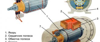
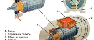
Figure 5 – Synchronous motor: 1 – brushes and brush holders, 2 – commutator, 3 – armature winding, 4 – armature, 5 – stator, 6 – slip rings, 7 – stator winding, 8 – generator rotor, 9 – fan, 10 – generator housing, 11 – drive, 12 – frame
Commutator machines are electric motors, a complex device and require very careful maintenance and care, operate on direct and alternating current, and are used to create automation devices and electrical household appliances.
DC machines serve as electric motors and generators. They are used in the creation of electric drive devices in which it is necessary to regulate rotation speeds, for example, in complex industrial machines, equipment used for digging earth, metal processing, and also serve as a power source for communications equipment.
In household electrical appliances and automation devices, universal commutator electric motors are used that can operate on two types of current - direct and alternating.
In the recent past, DC electric machines were the most popular variable speed drive because of their ease of control. They work in almost all areas of industry and transport. Due to increased cost and maintenance requirements, they are being actively replaced by variable frequency AC drives.
Due to the widespread use of DC machines, DC generators have also become common. They were used as DC voltage sources for charging batteries in transport (diesel locomotives, motor ships, etc.), as well as in industry (generator-engine system). Due to the development of semiconductor technology, direct current generators are gradually being forced out of service and are being actively replaced by alternating current generators working in tandem with a semiconductor converter.
Electrical machines have many functions; they are capable of amplifying the power of electrical signals, converting voltage values or alternating current into direct current, etc. To perform such different actions, there are various types of electric machines (Figure 6).
Figure 6 – Classification of electric motors
An electric motor is a type of electrical machine designed to convert energy. Namely, this type of device converts electrical energy into motive force or mechanical work.
The electric motor is in great demand in many industries. They are widely used in industry, on machines for various purposes and in other installations. In mechanical engineering, for example, earthmoving and lifting machines. They are also common in various sectors of the economy.
Advantages of electric motors:
- ease of control and regulation of rotation speed;
- simplicity of design;
- high starting properties;
- compactness;
- Possibility of operation in different modes (motor and generator).
Disadvantages of electric motors:
- commutator motors require difficult preventive maintenance of brush-commutator units;
- high cost of production;
- collector devices do not have a long service life due to wear and tear of the collector itself.
