Date of publication: October 28, 2013. Category: Articles.
In practice, electrical installation organizations use a number of shaft alignment methods. Let us say right away that this article does not discuss modern, trendy laser shaft alignment systems, which have a fairly high cost. The article provides an overview of alignment methods and devices that can be manufactured in-house, which were used in the USSR and which are popular to this day. Such alignment systems include: alignment of shafts using one or two pairs of radial-axial clamps, alignment of shafts using coupling halves, alignment using a device with an electromagnetic clamp and indicators, . All of these methods, as well as the devices used, are discussed below in the same sequence.
Shaft alignment using one pair of radial-axial clamps
| Figure 1. Aligning double bearing shafts using one pair of radial axial brackets |
This method is most widespread in installation practice.
The design of radial-axial brackets and their fastening are shown in Figure 1.
The outer bracket 1 is fixed to the coupling half 2 of the installed machine, and the inner bracket 3 is attached to the coupling half 4 of the machine, which must be connected to the installed one. The brackets are secured using clamps 5 and bolts 6. During the alignment process, the lateral clearances a and angular clearances b are measured using feeler gauges, indicators or micrometers. In the last two cases, an indicator or micrometer head is installed in place of bolts 7 and 8.
Before starting the measurement, the coupling halves must be disconnected and the shafts moved apart so that the brackets and coupling halves do not touch when the shafts rotate. For greater measurement accuracy, minimum clearances a and b are set using bolts.
Regardless of the method of checking the alignment of the shafts, the gaps between the planes of the coupling halves or between the tips of the radial-axial bracket are measured with a feeler gauge so that the feeler plates enter the gap with noticeable friction and to a depth of at least 2/3 of their length (almost up to 20 mm). Due to the fact that when measuring with a probe, errors are inevitable, the magnitude of which depends on the experience of the performer, the measurement results should be monitored. With correct measurements, the sum of the numerical values of even measurements is equal to the sum of the numerical values of odd measurements, that is
a1 + a3 = a2 + a4 and b1 + b3 = b2 + b4.
In practice, we can assume that the measurements were made correctly if the difference between these amounts is no more than 0.03 - 0.04 mm.
Otherwise, without changing the position of the coupling halves, the measurements should be repeated more carefully.
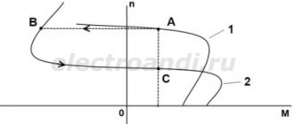
Figure 2 shows four relative positions of machine shafts.
Figure 2. Mutual positions of machine shafts
In position A, the shafts are located on the same straight line, and their centers coincide. Obviously, when turning the shafts simultaneously, clearances a and b must remain unchanged.
In position B, the shafts are parallel to one another, but there is a shift between them. When turning the shafts, the angular clearances b remain unchanged, but the side clearances a change.
In position B, the centers of the shafts coincide, but their axes are located at an angle. In this case, when turning the shafts, the values of the angular clearances b change, but the lateral clearances remain unchanged.
Finally, in position G, the centers of the shafts are shifted and their axes are located at an angle. When turning the shafts, the values of both angular b and lateral clearances a will change.
The first measurement of the gaps a1 and b1 is made when the brackets are in the upper position. Then the shafts are rotated 90° in the direction of rotation of the drive mechanism or generator and the gaps a2 and b2 are measured again when the marks on the shafts coincide. A total of four measurements are taken for each 90° rotation of the shafts. The fifth measurement is performed as a control when the staples again reach the upper position. The size of the gaps in the first and fifth positions of the brackets must match.
| Figure 3. Device for turning the shaft of a large or medium-sized machine |
To avoid inaccuracies in measurements, it is recommended to re-measure the gaps (by turning the shafts again to the same positions), and the measurements should be made by the same person.
The actual value of the gaps a and b at a given point will be half the sum of the corresponding gaps measured during two measurements at this point. Depending on the mass of the rotors, the shafts are turned either manually or using a crane.
The shaft rotation of low-power electric machines is done manually without any tools. To manually rotate the shaft of a large or medium-sized machine, it is recommended to use a special device shown in Figure 3. It consists of lever 1, tape 2 and clamp 3 for the tape.
| Figure 4. Scheme of turning the shaft of a large electrical machine using a crane |
Rotating the shaft using a crane (Figure 4) is carried out when installing large electrical machines with a power of 1000 kW or more. In this case, several turns of steel rope 2 with loops 3 and 4 at the ends are wound onto shaft 1. Loop 3 is hooked to bolt 5 passing through the hole in the coupling half, and loop 4 is attached to the hook of the crane, which uses rope 2 to rotate shaft 1.
Before measurements (after the shafts have been rotated to the required angle), the rope must be loosened. To eliminate the possibility of the coupling halves approaching or diverging when turning the shafts (axial movement), the latter must be locked with special stops (Figure 5).
| Figure 5. Locking stop |
Sometimes, if the unit shafts are located close to the foundation, it is difficult or impossible to measure the gap between the coupling halves at the bottom. In such cases, gaps are measured only at three points, that is, at the top and sides, and the size of the gap in an inaccessible place is determined by calculation, based on the fact that the sum of the gaps “top” plus “bottom” is equal to the sum of the gaps “side1” plus “side2” . With an unknown gap between the coupling halves from below, this equality is written as follows: b1 + x = b2 + b4, whence the unknown gap x = (b2 + b4) – b1.
After substituting the numerical values of the side and top gaps into this equality, the unknown gap from below is determined.
| Figure 6. Scheme of applying marks on the rims of coupling halves for measuring with a feeler gauge |
After each movement of the shafts in one position or another, all subsequent measurements are performed only after the motor feet or bearing stands are securely attached to the foundation plates. Otherwise, when tightening the bolts after measurement, the alignment will be disrupted.
The gaps between the planes of the coupling halves are measured with a feeler gauge at the same points. To do this, marks 1 are marked on the rims of the coupling halves with the letter designations of top B, bottom H and sides B (Figure 6).
Example. Figure 7a shows the values of the measured gaps (in millimeters) for four shaft positions. The values of the side gaps are written above the circle, and the corner gaps are written inside the circle. The numbers in the designations of the gaps a1, a2, a3, a4 show the serial numbers of the gap measurements.
Figure 7. Example of shaft alignment using one pair of radial-axial brackets
Figure 7, b shows the dimensions (in millimeters) of the connected machine: distance from the coupling to the bearing 3 l1 = 300 mm; distance from coupling to bearing 4 l2 = 1600 mm; distance from the shaft axis to the bolt 5 r = 350 mm.
To ensure alignment of the shafts, it is necessary to displace bearings 3 and 4 of the connected electrical machine (with a power of more than 1000 kW), moving them along the plate or moving them in a vertical plane by adding or subtracting pads under the bearing posts.
Let us introduce the following notations: x1 and x2 – horizontal movement of bearings 3 and 4 along the plate to the right (Figure 7, c), if there is a (+) sign in front of x1 and x2, and to the left, if there is a (–) sign; you need to look at the end of the coupling (from the side of the installed machine); y1 and y2 – vertical movement of bearings 3 and 4 up if y1 and y2 are preceded by a (+) sign and downward if there is a (–) sign.
The required movement can be calculated using the following formulas, substituting into them the numerical values indicated in Figure 7, a and b:
Therefore, bearing 3 must be raised up by 0.23 mm and moved to the right (the “+” sign) by 0.16 mm; bearing 4 should be raised by 0.82 mm and moved to the right (the “+” sign) by 0.87 mm (see Figure 7, c).
From Figure 7, a it is clear that the sum of even measurements of horizontal and vertical gaps is equal to the sum of odd ones. Really:
a1 + a3 = a2 + a4 = 1.42 mm; b1 + b3 = b2 + b4 = 1.48 mm.
Using this equality, you can check the results of gap measurements. If the sums do not add up, it is obvious that the bracket is bending or the shafts have axial movements that must be eliminated.
Shaft alignment using two pairs of radial-axial clamps
For angular displacements of the shafts, that is, when a1 + a3 is greater or less than a2 + a4 (or b1 + b3 is greater or less than b2 + b4), it is recommended to use two pairs of brackets for alignment, shifted relative to each other by 180°, as shown in the figure 8, a, with one pair of staples measuring the side and corner gaps, and the other - only the corner ones. Both pairs of staples must measure corner clearances at the same radius (distance from the axis).
Figure 8. Shaft alignment using two pairs of radial-axial brackets
Measurements are carried out, as with the previous method, by sequentially rotating both rotors by 0, 90, 180 and 270°.
Figure 8, b shows a diagram with the letter names of the gaps being measured. Figure 8, c shows four positions at which measurements are taken. So, for example, in position II, two corner gaps bII4 and bII2 are measured, as well as one side gap a2; in position III – bIII1 and bIII3 and a3 and so on. Then the resulting angular gaps are determined, which are equal to half the sum of two angular gaps measured at the same point with one and then the other pair of staples, that is
Required movements y1 and y2; x1 and x2 are determined using the formulas given above (in the case of alignment with one pair of staples), substituting into them the values of the resulting angular gaps b1 and b2; b3 and b4.
Aligning shafts with coupling halves
One of the types of brackets for aligning shafts along coupling halves is shown in Figure 10, c, in the article “Precision measuring instruments and instruments used in the alignment of shafts of electrical machines” and Figure 9 below. A measuring bolt with a locknut is screwed into the bracket. The side clearances a are measured using a feeler gauge between the measuring bolt and the outer surface of the coupling half (an indicator can be used instead of the measuring bolt), and the angular clearances b are measured between the ends of the coupling halves.
| Figure 9. Aligning shafts with coupling halves. 1 – bracket; 2 – bolt; 3 – measuring bolt |
At each position of the coupling halves (0, 90, 180 and 270°), one lateral measurement and two or four corner clearances are measured. The average values of angular gaps for several measurements are determined as the arithmetic mean by dividing the sum of the numerical values of the gaps by the number of measurements (two or four).
Movements y1 and y2; x1 and x2 are calculated according to the formulas given in the case of alignment with one pair of brackets, substituting into them the average values of the axial clearances b1 and b2, b3 and b4.
When centering on coupling halves, it should be borne in mind that the alignment accuracy of rigid couplings that have movable joints (gear couplings) may be less than the alignment accuracy of elastic couplings. Therefore, for couplings with moving joints, it is necessary to ensure that there is no jamming at each measurement. This is done using a lever, which checks for free angular movement of the connected parts in both directions.
Assembling couplings
The alignment of the horizontal shafts is determined by alignment along the coupling halves. Radial and axial clearances during alignment are measured at the initial position of 0° and after rotating the shafts by 90°, 180° and 270° in the direction of working rotation. For each position of the coupling halves, the radial and axial clearance between the coupling halves is measured. To check the correctness of the measurements, after four measurements it is necessary to set the coupling halves to their original position (0°). The results of repeated measurements in this position must coincide with the initial ones, otherwise the cause of the deviation should be found and eliminated. The measurement results are recorded in a pie chart. The correctness of the measurement is checked by comparing the sums of the results obtained when measuring on opposite sides of the coupling halves. These amounts must be equal to each other. The permissible deviation should not exceed 0.02 mm.
The obtained measurements along the end and circumference can be reduced to zero by subtracting the smallest gap from the results obtained. In case of unsatisfactory alignment results and the need to move the shafts in the horizontal and vertical planes, determine the displacement values (Figure 4.40):
x1 = A × (L + l) / dm
;
y1 = A × l / dm
;
x2 = y2 = R / 2
;
x = x1 + x2
;
y = y1 + y2
;
x = A × (L + l) / dm + R / 2
;
y = A × l / dm + R / 2
,
where R = R1 – R2
– misalignment of shafts around the circumference;
A = A1 – A2
– misalignment of the shafts at the end.
Figure 4.40 – Shaft alignment diagram: I, II – measurement planes; 1 – centered shaft; 2 – base shaft; No. 1…No. 4 – supports
Centering using a device with an electromagnetic clamp and indicators
The device shown in Figure 10 was developed in the USSR, by the Moscow Design and Experimental Department (MOPEO) of the Tyazhpromelektroproekt Institute. By its design, this device allows measurements when aligning shafts using both indicators and a plate probe.
Figure 10. Aligning the shafts using a device with an electromagnetic clamp and indicators. 1 – square; 2 – indicators; 3 – holders; 4 – setscrew; 5 – magnetic circuit; 6 – electromagnet coils; 7 – cylindrical fingers (hinge); 8 – rotary pole shoes; 9 – half-coupling rim
The device consists of two U-shaped electromagnets, powered by flashlight batteries and equipped with hinged pole shoes, with which it is held on the rims of the coupling halves of the centered shafts. The shape of the pole shoes ensures that they adhere to the rims of the coupling halves, regardless of the diameter of the latter.
Installing two indicators directly on the device allows you to perform measurements simultaneously in the horizontal and vertical planes and with greater accuracy than when measuring with indicators mounted on tripods, when the measuring pin of the indicator slides along the rough surfaces of the rim and the end of the coupling halves. In the absence of indicators, the device allows you to take measurements with a probe. To do this, a measuring pin similar to a set screw 4 is installed in the indicator holder 3.
How to center units?
Before measurements, the tightness of the anchors and bearing housings is checked. Loose fastenings, the presence of cracks in the frame, foundation defects, and uneven settlement of the floor are the causes of misalignment during operation of the mechanisms.
The devices are installed on the coupling halves, then the misalignment is measured:
- radial in the vertical plane;
- radial in the horizontal plane;
- end in a vertical plane;
- end in the horizontal plane.
Based on the measurement results, the position of the shaft axes is adjusted. To do this, the supports are moved vertically using spacers, and horizontally with bolts located on the frame. The centering bracket is set to the position of the larger value of the misalignment parameter, after which the supports are moved by the amount of the actual misalignment.
The shafts are aligned alternately in the horizontal and vertical planes. After the process of moving and fixing the supports is completed, measurements are taken again. If necessary, they are adjusted again.
In cases where one of the shafts cannot rotate during alignment, the gaps between the planes of the coupling halves can be measured when only one shaft is rotating. To do this, use a special device 2, attached to the coupling half of shaft 1, which can rotate (Figure 11), or the brackets shown in Figure 10, b and c, in the article “Precision measuring instruments and devices used in the alignment of shafts of electrical machines.” This method is called the “one-point bypass” method.
| Figure 11. Aligning shafts using the “one-point bypass” method |
In this case, the lateral displacement a is controlled with a feeler gauge by the gap between the pin 4 of the device 2 and the rim of the coupling half 5 mounted on the shaft 6. The angular displacement b is measured using a feeler gauge 7 by the gap between the ends of the coupling halves 3 and 5.
When installing electrical machines with a power of more than 500 kW, there may be cases of alignment of machines with a single-bearing shaft or connections with mechanisms that have a gear drive. Below are recommendations for performing this work.
Alignment control devices
Experienced craftsmen are able to control the alignment by applying a metal ruler to the coupling and determining the alignment by the clearance. But for greater confidence, to meet the norm, you can use a plate probe or an ICH-0.01 indicator. The latter provides the necessary accuracy of 0.01 mm, which is enough to meet the standard.
First, the coupling halves are disconnected, and then devices for aligning the shafts of electrical machines are installed on them or on the shafts nearby. They must be rigid enough so that they do not bend during measurements. Measurements can also be carried out with the couplings connected.
After installing and strengthening the devices, the functionality of the indicator mechanism is checked. To do this, pull back the measuring rods and return them to their place. In this case, the arrow should return to its original position.
Axial and radial clearances are checked by simultaneously rotating both rotors from their original position at angles of 90°, 180° and 270° in the direction of rotation of the drive.
Alignment of machines with single bearing shaft
In this case, the centered (single-bearing) shaft rests at one end on a pre-aligned bearing, and its other end is positioned so that the protrusion of one coupling half fits into the groove of the other. This connection of the coupling halves, as indicated in the article “Couplings for connecting shafts of electrical machines,” is called a flange connection and is shown in the said article in Figure 1, a.
Thus, the centered single-bearing shaft rests with one end on the collar of the half-coupling, and with the other on its bearing. A small axial gap of 1 - 2 mm is left between the ends of the coupling halves. During alignment, both coupling halves are connected with two or three bolts, the diameter of which is slightly smaller than the diameter of the coupling bolts. The bolts fit exactly into the holes of the coupling halves. Then alignment is carried out along the coupling halves, as in the case of double-bearing shafts. The necessary movements are calculated using the same formulas as when centering double-support shafts with one pair of brackets.
After alignment, you should check the correctness of this operation, since as a result of uneven tightening of bolts, inaccurate processing of the ends of the coupling halves, and so on, distortions may occur and alignment may be disrupted.
| Figure 12. Device for lifting the shafts of medium and large electrical machines to a small height |
To check, two indicators are installed on the journal of a single-bearing shaft: one in the vertical plane and the other in the horizontal, attaching them to the bearing (in place), and note the readings of the indicator installed in the vertical plane. Then, using a device (Figure 12), lift the end of the shaft, remove the lower bearing shell and return the end of the shaft to its previous position; the indicator installed in a vertical plane should give the same reading. By rotating the rotor by 0, 90, 180 and 270°, determine the amount of runout of the shaft ends using an indicator installed in the horizontal plane.
The correct alignment and connection of the coupling halves is determined by the amount of runout of the shaft end.
In the absence of manufacturer's technical specifications, the following maximum permissible values for shaft end runout should be used, depending on the speed of the machine:
| For machines with rotation speed, rpm | Maximum permissible value of shaft end runout, mm |
| up to 1000 from 1000 to 1500 from 1500 to 3000 | 0,15 – 0,20 0,12 – 0,15 0,05 – 0,08 |
Alignment of shafts of electric machines with gear transmission
In this case, the gearbox is taken as the alignment base, and all movements are made by an electric machine aligned to the gearbox. It should be taken into account that the shaft of the drive wheel of the gearbox during operation usually rises by the amount of the vertical clearance in the bearings, therefore the shaft of the aligned electric machine is installed above the gear shaft by the mentioned value of the vertical clearance.
In the practice of electrical installation organizations, there are cases when the drive motor shaft 1 is connected to the gearbox shaft 4 using an intermediate shaft that does not have bearings, as shown in Figure 13. Such cases, in particular, occur when the drive motor is connected to the stand gearbox rolling mills.
| Figure 13. Shaft alignment with an intermediate shaft |
The length of the intermediate shaft reaches 1.5 - 2 m and direct verification of the relative position of the shafts of the drive motor and gearbox using a probe, indicator or other measuring tool in such cases is impossible. To do this, the simplest way is to center the shafts using specially made squares 2 and a sight line 3 (Figure 13).
The outer sides of each square should be planed at an angle of 90°. The angles are attached with one side to the end planes of the coupling halves, and a string of thin steel wire is pulled along their other sides. Both lateral and angular displacements of the motor and gearbox shafts are measured using the string and angles. To fasten the squares to the planes of the coupling halves and to tension the sighting line, bolts and nuts are used. When choosing the diameter of the bolts and tightening the nuts, it should be taken into account that any large movement of the bolts in the holes of the coupling halves during the rotation of the shafts can lead to incorrect measurements and unsatisfactory quality of alignment.
Subscribe to the newsletter
Pumps of various types are common both in industry and in everyday life. They are used for water supply to industrial facilities and populated areas, in the chemical industry for pumping aggressive media, in the agro-industrial complex for irrigation, etc. Safe operation of pumping equipment directly depends on the correct alignment of the drive motor shafts and the pump itself. Correct alignment of the pump with the electric motor helps minimize vibration of the unit, which over time causes premature failure of bearings, bending of shafts and wear of working parts. This problem is most acute in industry for pumps with large volumetric flow, equipped with high-power motors. Monoblock units do not require alignment, since the impellers are pressed directly onto the elongated motor shaft. This procedure is necessary for units in which the connection between the pump and the electric motor is made using a coupling.
Types of misalignment: To correctly connect the pump to the electric motor, it is necessary to prevent the occurrence of misalignment (collinearity) between the shafts. The geometric axes of rotation of the pump and drive motor shafts, connected to each other by a coupling, may not coincide if installed incorrectly. Such a divergence can be parallel (a), angular (b) or mixed (c)
With parallel misalignment, the rotation axes of the shafts are located in the same plane at a certain distance from each other vertically or horizontally. The amount of misalignment of this type is equal to the distance between the axes of the shafts in millimeters. With angular collinearity, the rotation axes of the shafts are located at an angle to each other, resulting in the opening of the coupling halves. To numerically estimate the magnitude of this type of misalignment, it is necessary to measure the displacement of the axis of rotation of the motor shaft relative to the axis of the pump shaft in two places at a distance of 100 mm from each other. After this, the obtained data are added up, and the result obtained is divided by the distance between the measurement points. The magnitude of the angular opening of the couplings is expressed in mm/100mm. Mixed misalignment is characterized by a divergence of the axes of rotation of the shafts both in the vertical plane and in the angle. Both modern laser and analog instruments are used to measure shaft divergence
When is alignment performed?
Alignment of the pump and electric motor shafts is performed: • after installing new pumping equipment; • upon completion of major repairs with replacement of pipeline lines; • when vibration and increased noise occur during operation; • if the temperature of the bearing shields exceeds the nominal value.
How is alignment done?
Before performing alignment, the stationary and moving mechanism must be determined. In a pump-motor pair, the first unit occupies a stationary position, since a pipeline is usually already connected to it. Therefore, the center of rotation of the pump axis is taken as the reference line with zero coordinates. Based on the results of the measurements, the engine is aligned relative to the stationary unit. In the horizontal plane, misalignment is eliminated by moving the body of the electric machine to the right or left while simultaneously monitoring the angular misalignment, and vertical collinearity is eliminated by using adjusting pads under the feet.
If special measuring instruments are available, it will not take an experienced specialist much time to correct the misalignment.
But if there are none, centering the pump with an electric motor with your own hands using a ruler, calipers and plate probes will take a long time.
To check the collinearity of the shafts, you can also use two pieces of rigid wire, which are fixed to the coupling halves on the motor and pump sides and bent towards each other. For more accurate measurements, the free ends of the wires are shaped into a cone. There should be a gap of no more than 1 mm between the tips of the improvised indicators. Slowly turning the bolted coupling halves, use a feeler gauge to measure the gap every 90° in a plane perpendicular to the axis of rotation. Based on the results of the measurements performed, a decision is made on how to eliminate possible collinearity. The coupling of the engine with the driven mechanism through rigid couplings of various designs requires very precise alignment of the shafts. To reduce the likelihood of any type of collinearity, a flexible coupling is used to connect the shafts to connect the pump to the electric motor.
Source
Shaft alignment of multi-machine units
In multi-machine units of rolling mills, there are up to five electrical machines connected to each other, a very important condition is alignment (alignment of the shaft line) during the installation of the unit. In three- and five-machine low-speed converter units, normal synchronous motors are used as drive machines, the bearings of which are not designed for additional loads from generator armatures, which have only one bearing of their own.
To unload the drive motor bearings from additional loads on them caused by the suspension of generator armature shafts, S. M. Kirov (today's name is OJSC Power Machines) was the first to propose using a new method for aligning the line of machine shafts in such units.
The essence is that in order to uniformly distribute the loads on the bearings of the unit, it is planned to install individual shafts in such a mutual arrangement in which the planes of the flanges (Figure 14) would have some angular camber specified by calculation. So, for example, in a three-machine converter unit consisting of a synchronous motor and two DC generators designed to power the blooming drive motors, he proposed installing a common line of shafts so that there was a gap of 0.6 mm between the planes of the flanges of connection A (Figure 14), and the end planes of the flanges of connection B were parallel.
Figure 14. Alignment diagram for a three-machine unit. I, III – generators; II – drive motor
At the same time, for such units the manufacturer indicates the load values on the bearings, determined by the calculation method.
As a rule, electrical machines of these units are delivered to the installation site in disassembled form. Before starting work on aligning the shaft lines of multi-machine units, foundation slabs are installed and aligned, anchor bolts are tightened, bearing stands, stators and lower half frames are installed, rotors are inserted into stators, and in DC machines - armatures. In addition, it is necessary to carry out the following preparatory work: – familiarize yourself with the factory sketch of the unit. The sketch must indicate the numbers of machines, bearings, flanges, as well as the load on the bearings of the unit, the angular camber values of the flanges with the calculated data for installing the shaft line given in the technical documentation of the manufacturer; – check the serviceability of the device for determining the loads on bearings (Figure 15) and the possibility of using lifting and transport mechanisms available at the installation site for this purpose (the weight of the shaft with the rotor or armature should not exceed the lifting capacity of the crane); – determine the required cross-section of the slings and select them depending on the maximum load on the bearing being tested when weighing the part of the shaft with the rotor (armature).
Operations to align the shaft line of the unit based on calculated data are performed in the following technological sequence: - measure and adjust the slopes of the shaft journals of the middle machine of the unit, which has two of its own bearings, so that the shaft journals are at the same height relative to the horizontal plane, and also align and secure the bearing racks of this machine; – align the shaft of the machine, which has one bearing frame, to the aligned shaft of the average machine, for which purpose: check the compliance of the dimensions of the centering protrusion and the sharpness of the mating flanges; insert the centering projection of the flange of the attached shaft into the groove of the flange (or coupling half) of the aligned shaft of the middle machine; measure and adjust the gap between the ends of the flanges, install and tighten temporary coupling bolts; – center the shaft of the second machine to the aligned shaft of the middle machine and, alternately, on each side, the shafts of the remaining machines of the unit (in the sequence described above);
| Figure 15. Installation diagram of a device for determining loads on bearings of multi-machine units using the weighing method. 1 – indicator; 2 – handle for manual drive of the hydraulic jack; 3 – dynamometer earrings; 4 – dynamometer; 5 – sling made of steel rope (to the overhead crane); 6 – device for smoothly lifting the unit shaft; 7 – hydraulic manual jack; 8 – universal sling made of steel rope; 9 – bearing stand; 10 – rotor shaft (armature) |
– check the rigidity of the flange connection with rough bolts, as well as the reliability of fastening of the bearing struts; – hang the dynamometer with a device for smoothly lifting the shaft to the hook of the overhead crane (see Figure 15); – remove the covers and upper bearing shells, and then fix the indicator on the stand of the bearing being tested; – hang the weighed part of the shaft 10 from a dynamometer mounted on a device for smoothly lifting the shaft; – carefully lift the crane hook with the suspended shaft until the slings are tensioned and the dynamometer needle begins to move; – continue lifting the shaft using a hydraulic manual jack installed between the brackets of the device for smoothly lifting the shaft until the indicator arrow deviates by 1 - 3 divisions, which indicates separation of the shaft from the bearing shell; at the same time, the first recording of the readings of the dynamometer and indicator is made at the moment the shaft is separated from the bearing shell; – carefully lower the shaft with a hydraulic jack until the indicator deflects by 1–3 divisions and re-record the readings of the dynamometer and indicator; – compare data on actual loads on the bearing with the calculated load; determine the actual loads on all other bearings in the same way; – if necessary, redistribute the loads on the bearings by changing the height of the bearing posts; – draw up a protocol based on the weighing results; – unscrew the nuts of the temporary bolts and re-measure the gaps between the flanges; – compare the results of measurements between the flanges and the original ones corresponding to the calculated ones; – remove the devices for smooth lifting and weighing of the shaft and release the overhead crane; – install the upper bearings and bearing caps; – replace the temporary bolts on the flanges one by one with permanent ones.
Alignment tolerance
The values of lateral and angular clearances checked after alignment with brackets 250 - 300 mm long when both rotors are rotated together by 0, 90, 180 and 270° (or 0, 120 and 240°) should not differ by more than 0.03 mm. With a different length of staples, the tolerances for angular gaps must be changed in proportion to the length of the staples (up or down, respectively).
When centering on coupling halves for the same shaft positions, the lateral and angular clearances for couplings with a diameter of 400 - 500 mm should not differ by more than 0.05 mm.
The amount of permissible runout of the shaft end is usually indicated by the manufacturer and, as already mentioned, depends on the speed of the machines.
Factors affecting unit alignment
If the journals of the unit shaft coupling halves have a deflection, then it is impossible to center them within normal limits, since the amount of deflection will affect the alignment measurement.
When the pump is operating, alignment can be disrupted by loads from pipelines when supports are destroyed or their deformations are insufficiently compensated. According to the requirements of the technical specifications, pipelines should not transfer loads to the pump.
Source: Magazine “Heat Supply News”, No. 03 (03), November 2000, www.ntsn.ru
Final installation of the shaft line
When installing medium and large electrical machines, vertical and horizontal movement of the rotor within small limits (to avoid disturbing the necessary fit of the shaft journals in both lower bearings) is carried out by corresponding movement of the bearing posts. It should be taken into account that with the stator installed, such movement of the racks together with the rotor requires a corresponding movement of the stators themselves, since otherwise the gaps between the stator and the rotor will be damaged.
The correct position of the rotor is achieved by moving the foundation plate. After several movements of the foundation slab and bearing stands, a large number of temporary spacers may appear underneath them, which should be replaced with permanent ones, manufactured strictly according to the dimensions of the temporary spacers.
The gaskets are replaced in each place one by one, since knocking out the gaskets at the same time can lead to deformation of the foundation slab. Before changing temporary gaskets, marks are made on the slab at the location of their installation. Permanent gaskets are adjusted according to these marks and installed by knocking them out with light blows of the handbrake. They should be installed tightly enough, but without loosening other gaskets, which is checked with a feeler gauge and tapping with a handbrake on both the gasket being installed and adjacent gaskets.
Then they check the tightness of the anchor bolts, the bolts securing the rack, and the alignment, after which they weld the nuts of the anchor bolts to the plate with a short seam, bolt the rigid coupling halves, and also finally check the alignment and clearances between the stator and the rotor.
It is also necessary to make sure that when rotating the rotor does not touch the stator shields. To do this, a trial installation of stator shields is carried out on medium and large electrical machines. If there is jamming, the rotor run-up is slightly reduced by moving the bearings in the axial direction. After this, with blows of a lead sledgehammer or hammer, control conical pins are installed in the bearing struts and stator legs (two pins for each stand and for the stator). First (before checking the holes of the mating parts), non-insulated pins are installed to avoid damage to the insulation, and then insulated ones. After this, they fill out the machine passport, which indicates all the alignment data, gaps between the stator and rotor, gaps in bearings, slopes of the shaft journals, etc.
Assembly, fitting and connection of couplings
These operations are performed after the final alignment of the shafts.
Before connecting machines with rigid or semi-rigid couplings, it is necessary to make sure that there are no potholes, scratches, burrs and other irregularities on the end surfaces of the coupling halves, and then drill out the rough-drilled holes for the connecting bolts. Each hole is deployed simultaneously in both coupling halves (the coupling halves must first be tightened with temporary bolts).
Then, before and after installing all connecting bolts, the radial runout of each coupling half should be determined at four points spaced 90° from each other. If, as a result of inaccurate reaming, the runout exceeds the alignment tolerance, you need to re-ream all the holes with reamers of a larger diameter and replace the connecting bolts.
Movable connections made using gear couplings are checked after assembly for the possibility of angular (axial) displacement of the shafts due to their thermal expansion, the sufficiency of the gap between the covers and the ends of the hub teeth, as well as between the ends of the hubs (see Figure 1, c, in the article “Couplings” for connecting shafts of electrical machines"). In addition, in gear couplings, the clearances in the gears and the correct pitch of the teeth are checked (deviations in tooth thickness and pitch are allowed ±0.05 mm).
When assembling spring couplings, check the dimensions of the grooves between the teeth of the coupling halves (they must be strictly identical) and the possibility of axial movements of the springs. In addition, you need to make sure that the springs are not pinched.
For finger elastic couplings, check the diameters of the rubber or leather padding, as well as the holes for them. It should be borne in mind that the elastic part of the fingers must fit freely into the holes (the difference in diameters is allowed 2 - 4 mm). The gaps between the ends of the coupling halves are allowed within 5 - 8 mm.
A prerequisite for assembling and adjusting couplings is the uniform fit of the elastic part of all fingers to the surface of the holes along their entire length (in the driven half of the coupling). The correct position of the fingers is checked as follows: after installing each finger, the presence of displacement of one half of the coupling relative to the other is determined by gently rocking one of the rotors in both directions. In this case, it is necessary to ensure that the amount of displacement of each of the fingers is the same. If no displacement is detected when installing a pin, the cause may be improper installation or processing of the pin or incorrect bore dimensions in the driven coupling half.
Fitting coupling halves onto shafts
Boring of holes in coupling halves must be done in accordance with the instructions of OST 1022 (according to the shaft system):
| Shaft diameter in mm | 60 | 80 | 100 | 120 | 140 | 160 | 180 |
| Maximum deviations in microns | 0-20 | 0-20 | 0-23 | 0-23 | 0-27 | 0-27 | — |
| Hole diameter in mm: | |||||||
| with a tight fit maximum | 60,00 | 80,00 | 100,00 | 120,00 | 140,00 | 160,00 | 180,00 |
| with a tight fit, minimal | 59,97 | 79,97 | 99,96 | 119,96 | 139,96 | 159,96 | 179,96 |
| with a tense landing maximum | 60,00 | 80,00 | 100,00 | 120,00 | 140,01 | 160,01 | 180,01 |
| with a tense landing, minimum | 59,97 | 79,97 | 99,97 | 119,97 | 139,97 | 159,97 | 179,97 |
Before seating the coupling half (Fig. 1, a), it is necessary to check the assembly points on the shaft and in the hole. Taper and ovality are allowed no more than 0.05 mm. It is necessary to check the diameter of the paired coupling halves, the holes for the fingers, the coaxiality of the location of these holes, and the uniformity of their location around the circumference. Using a micrometer, check the diameter of the shaft, the dimensions of the key and its socket. Based on the indicated dimensions, draw up a sketch and make two micrometric bore gauges (shtihmas) from wire with a diameter of 6 mm so that the boring of the coupling half is ensured for a tight or stressed fit.
Before seating, the coupling half is heated in hot water to a temperature of 80° and lightly tapped onto the shaft. If the diameter of the hole is larger than the diameter of the shaft, then it is allowed to press in the bushing and then bore it to the size of the shaft. The wall thickness should be at least 8-10 mm. Place the bushing in the coupling half with a blind fit. The side edges of the key should fit tightly into the socket. In the radial direction, the key should have a gap of 0.1-0.4 mm.
Rice. 1. Fitting the coupling halves onto the shafts:
a – half-coupling for connecting the smoke exhauster shaft to the electric motor shaft,
b – adjustment and installation of connecting fingers,
1 – finger,
2 – leather or rubber rings,
3 – washer.
The connecting pins must fit the metal part into the hole of the drive half of the coupling tightly by hand. Leather or rubber rings should not rotate freely around the bolt (Fig. 1, b); they should fit into the hole of the coupling half with a gap of c = 1.5 - 2 mm. After installing each finger, check the displacement of one coupling half relative to the other by turning the driving half of the coupling by hand with the driven half stationary. If, after installing the finger, no displacement is detected, then the finger does not have a gap and the leather or rubber ring needs to be machined. All pin nuts must be cottered.
Source
Pouring foundation slabs and anchor bolts with concrete
After the final installation of the machine, acceptance according to the certificate, alignment of the machine (or unit), the construction organization, under the control of installation personnel, fills the foundation slabs with concrete mixture. Before pouring, the poured parts of the foundation are notched; the contact surface of old concrete with the gravy is thoroughly cleaned, especially from oil and kerosene, washed and continuously moistened for several days before gravy.
It is allowed to start the machine no earlier than 10 - 15 days after gravy (at normal hardening temperature).
When pouring concrete for foundation slabs and anchor bolts in winter conditions with an average daily outside temperature below 5°C and a minimum daily temperature below 0°C, concrete work should be carried out in accordance with the instructions of the “Building Norms and Rules” (SNiP).
Concrete mixture laid in winter conditions should be cured primarily using the thermos method, which is based on the use of insulated formwork and a protective coating in order to slow down the cooling of the concrete. To perform concrete work in winter conditions, accelerating the hardening process is a very important condition. The most suitable for this purpose are fast-hardening Portland cements of high grades (500 and above). The concrete mixture should not contain particles of ice, snow and frozen lumps of cement. To accelerate the hardening of concrete in winter conditions, chemical additives are used - chloride salts (calcium, sodium or ammonium). The total amount of chloride salts introduced into the concrete mixture should not exceed 7% of the cement mass (counting anhydrous salts) or 15% of the mixing water. The ratio of salts added to concrete required for each individual case is determined according to the relevant instructions.
Source: Kaminsky M.L., “Alignment of shafts of electrical machines” - Moscow: Energy, 1972 - 72 p.