Dynamic (electrodynamic) braking
If you disconnect the motor from the AC power supply and connect it to a DC source, dynamic braking will occur. The stator winding, when direct current flows, will create a stationary magnetic field. When rotating in such a field, an EMF will be induced in the rotor, under the influence of which a current will flow. This current will interact with the stationary field of the stator and create a braking torque, which will be directed against the direction of rotation of the rotor. As a result, the engine will gradually stop, and the speed of its stopping will depend on the strength of the direct current flowing through the stator, and, of course, on the stored kinetic energy of the electric drive. This energy, converted into electrical energy, is dissipated in the form of heat on the rotor.
Regenerative (generative) braking
Regenerative braking is used mainly as a brake before the main braking, or when lowering loads, for example in elevators.
For regenerative braking to occur, the rotor speed must exceed the synchronous speed. In this case, the engine will begin to supply energy to the network, that is, it will become an asynchronous generator. In this case, the electromagnetic torque of the motor becomes negative and has a braking effect.
Generator braking can be achieved in several ways. For example, in two-speed engines, when switching from a higher speed to a lower one. In this case, the rotor rotates by inertia at a frequency higher than the new synchronous frequency. A braking torque will occur, which will reduce the speed to the new nominal speed.
Let us assume that at the initial moment of time our engine was operating at characteristic 1 at point A, after switching the speed to a lower one, it switched to characteristic 2 at point B, and then, under the influence of the braking torque, reached point C, at a lower speed.
Generator braking can be achieved by reducing the frequency of the motor supply. This is possible if the motor is powered by a thyristor frequency converter. As the voltage frequency decreases, the synchronous rotation speed decreases. The rotation speed of the rotor, which rotates by inertia, will again be higher, and a braking torque will arise, which will reduce the rotor speed. In this way, the engine can be brought to a complete stop.
Back braking
Back braking is used to quickly stop the engine. This can be done in several ways. In the first method, with the engine running, two phases are swapped by turning off contactor K1 and turning on K2. In this case, the direction of rotation of the stator magnetic field changes to the opposite. A large braking torque occurs and the engine stops quickly. But in order to limit large currents at the moment of increasing braking torque, it is necessary to introduce additional resistance into the stator or rotor winding.
In the second method, the engine is used as a brake for the load. That is, if the load goes down, then the engine should work, on the contrary, to rise. To do this, a large additional resistance is introduced into the motor rotor circuit. But its starting torque turns out to be less than the load torque, and the engine operates at a certain low speed, thereby ensuring a smooth descent.
In essence, counter-switch braking is carried out according to the engine reverse circuit.
Countercurrent braking principle
The motor is disconnected from the power supply, and while the rotor continues to rotate, it is reconnected in antiphase. Such a system creates an effective locking torque, usually higher than the starting torque.
Meanwhile, this effective braking torque must be quickly neutralized so that the engine does not rotate in the opposite direction after stopping. Several control and automation devices are used to ensure that the rotation of the electric motor shaft is slowed down until it stops completely:
- clutch stop sensors,
- centrifugal stop sensors,
- chronometric instruments,
- frequency relay,
- rotor voltage relay (for wound-rotor motors), etc.
Braking a squirrel-cage motor
Before choosing a countercurrent system for an asynchronous motor with a short-circuit rotor, it is important to ensure the resistance of the motor to the countercurrent method, taking into account the required load.
In addition to mechanical stress, this process exposes the rotor to high thermal loads as the energy generated by each operation is dissipated in the rotor body.
The thermal stress in the counterflow is three times greater than when the rotation speed increases. Here the peaks of current and torque are noticeably higher when compared with the starting moment.
The principle of the countercurrent technique on the electric motor circuit in order to quickly slow down and then stop. On the left is the normal operating cycle. On the right is the deceleration and stopping cycle
Therefore, to ensure a smooth stop of the engine by the countercurrent system, as a rule, a resistor is installed in series with each stator phase. Thanks to this addition, when switching, the torque and current are reduced to values equal to those noted on the stator in starting mode.
Braking during self-excitation
If the power to the motor is turned off, its magnetic field will die out only after a short period of time. If at this moment you connect a battery of capacitors to the stator winding of the motor, then the energy of the magnetic field will first be transferred to the charge of the capacitors, and then returned to the stator winding. This will create a braking torque that will stop the engine. This type of braking is often called capacitor braking.
The magnitude of the braking torque will depend on the capacitance of the capacitors; the larger the capacitance, the greater the torque
The capacitors can be permanently switched on or switched off while the engine is running using a contactor.
You can do without capacitors by simply closing the stator winding in a star configuration using keys SA, having previously disconnected it from the network using contactor K. Then braking will occur much faster, due to the residual magnetism of the motor. This braking is also called magnetic braking.
Self-excitation inhibition
Self-excitation braking circuit
This option is implemented by connecting the stator windings to a parallel capacitor bank or bridge (the capacitance will have to be calculated). When the motor is disconnected from the network and the coasting mode must occur, the fading magnetic field begins to power the capacitors, and through them returns back to the winding, creating a braking torque.
As you can see, in practice, a whole range of specific operating modes of asynchronous motors is used, which can be used to quickly and accurately stop it. With frequent starts and stops, dynamic, regenerative, reverse (on starters) or capacitor braking (through bridge or battery calculation) can increase the efficiency of equipment operation and reduce time loss.
Source
Subscribe to the newsletter
Production processes involving the operation of equipment equipped with AC or DC electric motors require periodic shutdowns. However, after disconnecting the supply voltage from the electric motors, their rotors continue to rotate by inertia and stop only after a certain period of time. This stopping of the electric motor is called freewheeling.
For electric motors that operate with frequent starts and stops, free coasting is not suitable. To reduce the time required to completely stop rotor rotation, forced braking is applied. Electric motor braking methods are divided into mechanical and electrical.
Mechanical braking
Stopping engines with this method of braking is carried out thanks to special pads on the brake pulley. After turning off the supply voltage, the brake pads are pressed against the pulley under the influence of springs. As a result of the friction between the pads and the pulley, the kinetic energy of the rotating shaft is converted into thermal energy, which leads to its complete stop. After applying voltage, the electromagnet (YB) releases the brake pads, and operation of the electric motor continues in normal mode.
Depending on the electrical braking circuit, the kinetic energy of the rotating rotor can be transferred to the network or to a battery of capacitors, and also converted into heat, which is absorbed by the windings of the electric motor or special rheostats.
Dynamic motor braking
This stopping circuit is suitable for three-phase electric motors with both squirrel cage and wound rotor types.
Dynamic braking of an electric motor with a squirrel-cage rotor is carried out by disconnecting the stator windings from the three-phase alternating current supply network and switching two of them through a system of contactors and relays to a source of rectified direct voltage.
The stator windings, after applying constant voltage to them, generate a stationary magnetic field, under the influence of which in a short-circuited “squirrel cage”
rotating rotor, an electric current begins to be induced, causing the appearance of a tomosive moment. The direction of this moment is opposite to the direction of rotation of the stopping shaft. After stopping the engine, the supply of direct voltage to the stator windings is stopped.
In motors with a wound rotor, the amount of braking torque can be adjusted using additional resistances, which are used as starting resistors.
Back braking
Braking of an asynchronous electric motor using the back-to-back method is carried out by reversing the motor without disconnecting from the supply network.
Braking control is performed by the speed control relay. In operating mode, the relay contacts are closed. After pressing the “STOP” button (SBC), the group of contactors switches two phases, changing the order of their alternation. As a result, the stator's magnetic field begins to rotate in the opposite direction, which causes the rotor to slow down. When the rotation speed becomes close to zero, the speed control relay opens its contacts and the supply voltage is stopped.
Capacitor braking of electric motors
This method, also called self-excited braking, is applicable only to electric motors with a squirrel-cage rotor.
After the supply voltage is stopped, the electric motor rotor continues to rotate by inertia and generates an electric current in the stator windings, which first charges the capacitor bank, and after accumulating the rated charge returns to the windings. This leads to the occurrence of a braking torque, the magnitude of which depends on the capacity of the capacitor banks connected to each phase in a star or delta configuration. Self-excited braking is used on engines with a large number of starts and stops, since the amount of energy loss in the engines with such a stopping scheme is minimal.
Regenerative braking
Braking of an asynchronous electric motor in regenerative mode occurs when the rated rotor speed exceeds its synchronous frequency. The engine begins to generate electrical energy and send it to the power supply network, resulting in the creation of a braking torque. This stopping method is used for multi-speed motors by gradually switching from a higher rotor speed to a lower one. Thus, at a certain moment, the speed rotating under the influence of the inertia of the shaft will be greater than the synchronous frequency corresponding to the connected number of stator poles. In addition, a regenerative braking circuit is used for motors connected to frequency converters. To do this, it is enough to reduce the frequency of the supply voltage.
Stopping DC motors (DCM)
Braking of DC electric motors is carried out by counter-switching and in a dynamic way.
Dynamic braking
This braking circuit is used for motors with independent excitation.
After pressing the “Stop” button (SB1), the armature windings are disconnected from the supply network and reconnected to the braking resistor. In the windings of the armature, rotating by inertia in a stationary magnetic field, a direct current is induced, which, passing through the winding wires of the resistor, is converted into thermal energy.
Back-up braking The back-up method is based on changing the polarity of the voltage connected to the windings of the inductor or motor armature. This results in a change in the polarity of the magnetic flux or the direction of the current induced in the armature. Thus, the direction of the torque is reversed, which causes a braking effect. The speed of rotation of the armature is controlled by a speed relay, which cuts off power to the armature when it approaches zero.
Braking trains using electric motors
Hello!
What is electrodynamic braking on locomotives and electric trains? Yes, in addition to pneumatic brakes, electric locomotives and modern diesel locomotives are equipped with electric braking. And it is called rheostatic and recuperative. How does this braking work?
In this article we will look at DC motors. Since they are installed on most electric locomotives, electric trains of both direct and alternating current. Any electric motor has an armature with a commutator, which has its own winding in slots, which rotates in the frame of the motor, and in the frame (stator) there is another winding - the field winding. Current flows through the armature winding and through the excitation winding, and as is known, a magnetic field is formed around each current-carrying conductor, and an electromotive force arises - EMF. Here the magnetic field lines of the armature and field windings add up and rotate the armature of the electric motor. But if the armature winding is de-energized and the current in the field winding is left, then the armature will rotate in the magnetic field of the field winding - then the electric motor turns into a generator. An EMF will be induced in the armature winding. In this case, an electromotive force (magnetic flux) arises directed against the magnetic flux of the field winding and, accordingly, against the direction of rotation of the armature; this force is called back-EMF. Simply put, braking force. This force is very large, and it is precisely this that plays the main role in electric braking.
Wheel-motor unit of a diesel locomotive
In general, traction electric motors (TEMs) are transferred from electric motor mode to generator mode by disconnecting the armature winding. Well, in order for electric current to begin to be generated in the TED, it is necessary to connect the armature to some kind of load - braking (ballast) resistances or to a contact wire.
Braking rheostats
When braking resistors are connected, such braking is called rheostatic, and when connected to a contact wire, it is called regenerative. On electric locomotives and electric trains of direct and alternating current, this process proceeds almost identically, although there are some design differences.
All switching to the appropriate modes is carried out from the control panel of the driver's controller, through the corresponding electro-pneumatic contacts in the power circuit of the locomotive, the amount of braking force is regulated. The operation of these systems requires serious protection from overloads and mandatory compliance with certain conditions, for example, the equality of the excitation flows of all electric motors must be ensured, which contributes to the uniform distribution of loads between the engines during braking and the rails must be dry. It is also necessary to intensively cool the braking resistors.
During regenerative braking, the current generated by the electric motor is supplied to the contact network. On DC electric locomotives, the generated current is constant, so it can immediately enter the contact network. But with alternating current it is more complicated; the current on the motors is constant, but in the contact wire it is alternating. Therefore, regenerative braking on AC electric locomotives is used only in the presence of rectifier-inverter converters (RIC). All modern AC electric locomotives operate on such converters.
In normal traction mode, the alternating current passing through the thyristors in VIPs is converted into direct current and is also regulated using the properties of thyristors. During regenerative braking, the current undergoes an inversion process, i.e., passing through the thyristors, it is converted from constant to alternating and enters the contact network. The use of recovery has a great effect. In some areas with steep slopes, energy savings of up to 20% can be achieved.
With any electric braking on descents, it is possible to ensure a constant speed of the train without using air brakes, especially on long descents. Frequent braking with pneumatics depletes the brake line, the speed first decreases and then increases again and it is necessary to apply the brakes again, the coefficient of friction of the pads decreases due to their heating. Thanks to electric braking, wear on brake pads and rolling stock wheels is significantly reduced. In passenger trains, the smooth running of the train and the comfort of passengers are ensured; in freight trains, strong reactions that occur when braking and releasing pneumatic brakes are eliminated. Well, on electric trains in suburban traffic and in the metro, electric braking plays a dominant role. Also, modern diesel locomotives are equipped with rheostatic braking systems.
Best wishes!
Similar
Methods for braking asynchronous motors
Lecture 18.
An asynchronous machine connected to a three-phase network can operate in motor modes (0 1, quadrant IV).
In electromagnetic brake mode, the directions of rotation of the stator and rotor fields are opposite and the mode is called counter-initiation braking . This braking is achieved by changing the direction of rotation of the stator field. In this case, the characteristic E1 is replaced by the inverted characteristic E2. To reduce the IM currents, the stator voltage is simultaneously reduced (characteristic I2). Operating point from a
1 jumps horizontally into
a
2 and then moves downward along the I2 characteristic.
When point a
3 (
n
= 0) is reached, the blood pressure must be disconnected from the network, otherwise a reverse will begin.
When the moment M
C is active (load in the lift), the second method of braking by counter-switching is possible: a large resistance is introduced into the rotor circuit (characteristic I1) and the IM is switched on for lifting.
Under the influence of the prevailing moment M
C >
M
p from point
a
4, the descent of the load will begin with braking.
At point a
5 of the intersection of characteristics I1 and
M
C, the descent frequency will be established -
n
2 (brake descent).
| Back-up braking characteristics |
Regenerative braking occurs when the engine goes into
This type of braking is observed in frequency-controlled motors when the frequency f
1, as well as in multi-speed engines when switching to low speed.
For example, with an increase in the number of pole pairs, characteristic E1 is replaced by E2, and the operating point a
1 jumps horizontally at point
a
2 and then smoothly along characteristic E2 at point
a
3,
a
4. Section
a
2
a
3 is a generator.
It corresponds to braking ( M n
1, i.e. it goes into generator mode, while the kinetic energy of the load is converted into electrical energy and supplied to the network.
Dynamic braking is carried out by disconnecting the stator windings from the three-phase network and connecting to a constant voltage source U
(Figure
a
).
The direct current I
of the stator windings creates a stationary magnetic field, under the influence of which currents are induced in the winding of the rotor rotating by inertia, creating a braking torque.
Artificial mechanical characteristics in dynamic braking mode (Figure b
) can be adjusted by changing the resistance
R
or
Rd
in the rotor circuit (curve
1
).
Curve 2
corresponds to a motor with a squirrel-cage rotor.
Dynamic braking: a
- scheme;
b
– characteristics
|
Characteristic n
(
P
2) is close in shape to the mechanical characteristic
n
(
M
) and is rigid.
The characteristic M
(
P
2) is close to linear, since
n
and Ω change little.
The dependence I
1(
P
2) begins from point
I
of idle speed, which for blood pressure is (0.25¸0.35)
I
1nom.
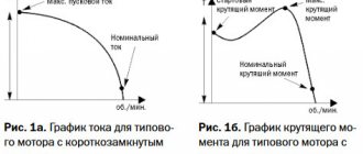
The power of all losses in the IM consists of the power of constant losses (mechanical and losses due to eddy currents and hysteresis) and the power of variable losses (heating of the stator and rotor windings). The efficiency η reaches its maximum when constant and variable losses are equal. For IM, this condition is met at the most probable load, i.e. at P
2 = (0.6¸0.7)
P
2nom.
The efficiency of micromachines is 0.4¸0.6, low- and medium-power machines – 0.7¸0.9, high-power machines – 0.9¸0.95. The power factor cosφ1 at idle is low (no more than 0.2). As the load increases, it increases and reaches a maximum at P
2 »
P
2nom.
For low and medium power engines at full load cosφ1 = 0.7¸0.9, for P
2 > 100 kW cosφ1 = 0.9¸0.95. The values of cosφ1 = 0.7¸0.9 correspond to the values of sinφ1 = 0.7¸0.3, i.e., even at full load, the share of the stator reactive current is 70–30%. When the IM is not fully loaded, cosφ1 is significantly reduced, and in modes close to idle, the IM loads the network mainly with reactive current. Therefore, full load of the IM is a necessary measure to increase the cosφ of industrial enterprises.
Source
Recommended files
Terms of Reference
Requirements Engineering and Software Specification
FREE
Maran Software Engineering
Software engineering
FREE
Sukhov A.V., Parygin K.E. — Liquid rocket engine fuels
Fuels and theory of working processes in liquid-propellant rocket engines
FREE
160700 (24.05.02).C1 Design of electric rocket engines
Supporting materials for freshmen
FREE
Baranovsky Yu.V. (1972) Metal cutting modes. Directory
Technological foundations of automation of processes and production
FREE
Testing of aircraft air-breathing engines G.M. Gorbunov E.L. Solokhin
VRE, LRE, Gas turbines
those. .
In the motor mode S>0 and the components and are positive, and the inductive current is.
In generator mode S<0. In this case, it does not change its sign, but the current changes sign (φ2 = 1800). Physically, this is explained by the fact that the field rotates relative to the rotor compared to the motor mode in the opposite direction. In this case, the sign of the EMF also changes.
The engine switches to generator mode. The electromagnetic torque also changes its sign and it becomes braking. Consequently, the engine already operates as a generator in parallel with the network, and supplies electrical energy while consuming reactive power for excitation. It should be noted that an asynchronous machine, both in motor and generator modes, consumes reactive energy from the network, i.e. generator mode is possible only if there is a network that is capable of supplying the asynchronous generator with the reactive power necessary to create a magnetic field.
Often the characteristics corresponding to the generator slip will be located in the second square (II). Therefore, this mode will correspond to slip values from “0” to “-”. In this mode, as can be seen from the formula for the critical moment, the critical moment has a larger value than in the motor mode.
Braking with energy recovery into the network is used in lifting and transport devices when lowering heavy loads. Under the influence of a descending load, the asynchronous machine begins to rotate at a speed. In this case, the machine goes into generator mode and begins to create braking torque. The steady equilibrium state will correspond to the point of intersection of the mechanical characteristics of the engine and the static torque line. In this case, the equality M>Mc is established and the load will descend at a steady speed.
To do this, in order to ensure normal braking release of the load, the static torque should not exceed the critical torque of the machine in generator mode.
If there is a reactive element
, static torque, then braking with energy recovery into the network is possible only if an asynchronous motor is used with switching the number of pole pairs.
Let us assume that the stator windings are connected in such a way that they provide fewer pole pairs, i.e. the engine runs at point A, at highest speed
If the windings are switched to a smaller number of pole pairs p2, then the motor will start working at point B on characteristic 2 passing through point
The motor rotation speed during switching will be greater than the synchronous speed corresponding to the new number of poles, i.e.
.
The machine will switch to generator mode. In Fig. 4.10, the area with energy transfer to the network corresponds to the VSD section of the mechanical characteristic.
This process is used (takes place), for example, in the drives of metal-cutting machines when switching engine speeds.
What is dynamic braking?
At this point, a logical question may arise: why invent something if you can disconnect the engine from the mains and it will stop on its own? This is undoubtedly true, but given the high rotation speed and mass-centering characteristics, it will take some time until the rotor comes to a complete stop. This period is called free run and everyone observed it in childhood, launching a simple spinning top. However, if the operation of the equipment involves frequent use of starters, then this mode leads to an obvious loss of time.
To quickly stop, braking modes are used, which involve the transformation of mechanical (in this case, kinetic) energy artificially. Everyone distinguishes two main types of inhibition, which are then divided into subtypes:
Dynamic braking of an asynchronous motor is of the electrical type, since during the process the stator winding is disconnected from the AC network (two of the three phases) and transferred to a closed DC circuit. In this case, the magnetic field in the stator is converted from rotating to stationary. An EMF will still be induced in the rotor, but the torque will be directed in the opposite direction, which leads to braking.
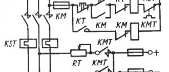
The classic scheme, as can be seen in the illustration, involves disconnecting one phase from the network using the KM1 contactor. In this case, the other two phases, due to the KM2 contactor, are switched into a circuit with direct current through a diode bridge.
The main advantage of this method of braking is the ability to smoothly control the braking torque (by changing the voltage or resistance) and carry out an accurate stop.
Main types of dynamic braking
Organizing a forced stop of an asynchronous motor using the electrical principle can be carried out in several ways:
- Electrodynamic. This is a classic option, in which two phases need to be short-circuited and transferred to DC power,
- Regenerative (generator). Characterized by the return of excess electricity to the network,
- Anti-inclusion. This option is implemented using a reverse circuit, that is, with the phases connected through a pair of magnetic starters,
- Self-excitation. By connecting a battery of capacitors to the stator windings.
Regenerative braking
Regenerative braking mode
Since the excess electricity released during braking is sent back to the network through the bridge/capacitor bank, this mode of operation is considered the most economical. Most often, this method is used in lifting and transport equipment and equipment that works to move loads or its own weight downhill. A classic example is an elevator, where regenerative braking from the drive motor is used for initial braking. Also, a similar scheme is widely used in electrified transport, for example, in trams, trolleybuses, and electric trains. It is also used in special equipment, for example, excavators, widely used in the construction of bridges, roads, buildings, etc.
The principle of calculation and organization of the generator mode is that the rotor speed exceeds its synchronous value. In this case, the electromagnetic torque changes direction, which leads to braking.
Three-phase asynchronous motors: methods of braking
Home page » Three-phase asynchronous motors: methods of braking
A significant number of drive systems are used to naturally slow down engines when stopped. The time it takes to stop the rotor is measured solely by the inertial moment and the moment of resistance to rotation. Meanwhile, the operation of systems often requires reducing the stopping time of the motor shaft, and in this case, electrical braking of the electric motor seems to be a simple and effective solution. Compared to devices that use mechanical or hydraulic methods, electrical braking of motors has clear advantages in terms of stability of operation and cost-effectiveness of use.
Back braking
Back-up braking circuit
In practice, the opposition regime can be organized in several different ways. The classic method is to use a pair of magnetic starters connected in a reverse circuit. In this case, a quick stop of the unit is carried out by changing the position of the phases (counter-switching).
The main starter KM2 disconnects the motor M from the network. After this, the parallel starter KM1 turns on the engine again, changing the extreme phases in places, that is, forcing it to rotate in the opposite direction. To prevent excessive overheating, additional resistance can be introduced into the circuit. Also, a counter-connection circuit can be implemented if the engine is used as a brake for a load.