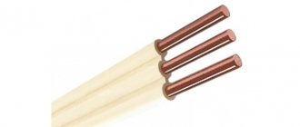
Straight wire inductance calculator
In practice, the most common wire used to power various electrical energy consumers also has a certain inductance.
Of course, the size of the inductance in this case is not commensurate with the inductance of the coils, but in certain situations, this value can have a significant impact on the operation of high-precision electronic devices. And since inductance is the ability to accumulate electrical energy, then on the scale of electrical networks, such accumulations can lead to incorrect operation of power plants, delayed response of protections, and residual electricity after a shutdown. Of course, the inductance of a straight wire for conductors on the scale of one apartment or the power cord of one household appliance is negligible. Since the inductance value of a straight wire is directly proportional to its length. But for lines with a length of several kilometers, this parameter becomes significant. To calculate inductance you need to use the formula:
L = 0.00508 * l * (log * (2 * l/D) - 0.75)
Where l is the length of the wire, and D is its diameter.
This value can be especially relevant when calculating short circuit currents in power supply lines. Which are necessary to determine the protection operation settings. You can use the formula for the calculation, but extracting the logarithm provides a number of inconveniences. Therefore, it is much more convenient to use an online calculator, which will allow you to determine the inductance without wasting time and any complex mathematical operations. To do this, you just need to indicate the length and diameter of the wire, and then click on the “Calculate” button.
Source
Coaxial Cable Inductance
A coaxial cable consists of two long coaxial conducting cylinders, the space between which is filled with some insulating material with magnetic permeability m.
Let a be the radius of the inner cylinder and b the outer one. The length of the cable is usually many times greater than its radius. Therefore, the magnetic field created by an electric current in a cable will be the same as that of an infinitely long cable, if we do not take into account the field distortions at its ends.
Let's find the inductance of a cable section of length l. To do this, we will create a closed electrical circuit from the internal and external cylinders of the cable and connect a source of constant EMF to this circuit (Fig. 8.6, a). The currents created by this EMF will flow along the surfaces of the cylinders along their axis in opposite directions.
| A) |
Due to the cylindrical symmetry of the system, the magnetic field lines are a family of circles whose centers lie on the axis of symmetry. In Fig. 8.6, and one of the lines of force is depicted. , we apply theorem (7.7) about the circulation of the vector H.
As an integration contour
C,
we choose a force line of arbitrary radius r. The circulation of the tension vector along such a contour will be
Hdl = Hdl
=
H dl
=
N 2pr
. (8.33)
H
Rice. 8.6. Coaxial cable
If the radius of the contour is C
is less than the radius of the inner cylinder (r <
a),
no current flows
inside circuit
C. In the case when circuit C
covers
Therefore, the magnetic field strength R = 0 for r < a
and
r > b,
i.e.
There is no magnetic field inside the small cylinder and outside the large one. If the radius of the circuit C
is such that
a
< r <
b,
then such a circuit covers only the current in the inner cylinder. In this case, according to theorem (7.7), circulation (8.32) will be equal to the current strength / in the circuit under consideration:
2prН = I.
Thus, the magnetic field strength inside the coaxial cable
H = I/2pr.
Magnetic field energy density in space, where a
< r < b
,
we find it using formula (8.28):
w = (1/2) mH2
= (1/2)
m I2 /8p2 r2.
(8.35)
Let's find the energy of the magnetic field inside the cable. To do this, consider a cylindrical layer formed by two imaginary cylinders of radii r and r + dr
(Fig. 8.6, b). If the length of the layer is l, then its volume
dV
=
2prldr.
Since the energy density (8.35) depends only on r, inside a thin cylindrical layer it will be the same everywhere. Therefore, the magnetic field energy in the layer
dW = w(r) dV =
(1/2)(
m I2 /
(
8p
2r2))2
prldr
.
Integrating this expression over r ranging from a
to
b,
we find the magnetic field energy on a cable section of length l:
W=
(1/4
p
)
m I2l =
(1/4
p
)
m I2l
ln(b/a) (8.36)
On the other hand, the magnetic field energy can be determined using formula (8.26). Let's equate these expressions and find the inductance of a section of coaxial cable with length l:
L= 2W/I2 =(1/2 p
)
ml ln
(b/a) (8.37)
Mutual induction
Let's consider two circuits with currents I1 and I2 (Fig. 8.7), located at some distance from each other. The current in the first circuit creates a magnetic field, the flow of which through the second circuit is obviously proportional to the current strength I2
y2 = L21 I1
(8-38)
Similarly, the magnetic flux F1 through the first circuit of the field created by the current in the second circuit is proportional to the current strength I2.
y1 = L12I2
(8.39)
L12 proportionality factors
and
L21
are called
mutual inductance,
or
mutual induction coefficients.
They depend on the shape, size, relative position of the circuits and on the magnetic permeability of the medium in which the circuits are located.
Rice. 8.7. Mutual induction
Let's look at a simple example. Let there be two windings on one cylindrical frame, forming two solenoids of the same length l (Fig. 8.8). The number of turns of one solenoid is N1,
and the second -
N2.
Let's find the coefficients
L12
and L21 for this system.
Rice. 8.8. Towards the calculation of the mutual induction coefficient
Let us assume that current I1 flows in the first solenoid,
and in the second -
12.
By virtue of (7.17), the magnetic field strength of the current
h
inside the solenoid
H1 = N1I1/l
The flux of magnetic induction of this field through one of the turns 2 of the solenoid
F2 = B1S =
m N1I1S/l
Since the field inside the solenoid is uniform, the fluxes through all turns are the same. Therefore flux linkage
y2 = N2 Ф2 = B1S =
m N1
N2
I1S/l
L21=
m N1
N2
S/l
Similarly, the field strength created by the current I2 will be
Н2 = N2I2/l
The flux of magnetic induction of this field through one of the turns of the first solenoid
F1 = B2S =
m N2I2S/l
F1 =
y2 = N1 Ф1 =
m N1
N2
I2S/l
From here we find that
L21 = L12
(8.41)
This equality is valid for any two contours and constitutes the content of the reciprocity theorem.
Let's calculate the energy of the magnetic field of two coaxial solenoids. Vectors of field strengths created by currents I 1
and I2 are collinear inside the solenoids.
If currents I1
and I2 flow in the same direction, then vectors H
1 and
H
2
are co-directed In this case, the total magnetic field is characterized by the intensity:
H = H1
+
Н2 =
(
N1I1 + N2I2
)/l (8.40)
If currents I1 and I2 flow in different directions, then vectors H 1
and
H 2 are directed opposite to each other.
In this case, the magnetic field strength modulus H =
|
H 1
+
H 2
|
=
|
H1
-
H2
|
=
(
N1I1 - N2 I2
)/l
We find the energy of a uniform magnetic field using formula (8.28):
W = (1/2) mH2V=
(1/2)
m
(
N1I1 ± N2 I2
)2V/
l2
Using formulas (8.22) and (8.40), we write this expression as follows:
W
= (1/2)
L1I1
2 + (1/2)
L2 I2
2
± L12I1 I2
where the first term is the current energy in the first solenoid, the second is the current energy in the second, and the third term is called mutual energy.
Formula (8.42) is valid in the general case for two arbitrary contours.
Task. Find the mutual inductance of a toroidal coil and an infinite straight wire passing along its axis. The coil has a rectangular cross-section. The internal radius of the toroid is a,
the outer one is
b,
and its height is
h.
The number of turns in the coil is
N.
The magnetic permeability of the environment is
m.
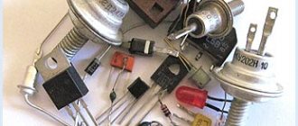
Calculation of the inductor
When building electronic devices, you often have to deal with an inductive circuit element. When only the inductance value L is indicated in the drawing, you have to calculate the inductor yourself. There are many programs on the Internet that allow you to calculate the inductance of coils online using a special calculator. Knowing how the element is structured, you can manually perform all the calculations.
Application
A microstrip line is a flat conductor separated by a dielectric from a large conducting ground plane. Microstrip lines were used because at very high frequencies the required inductance and capacitance values were very small for conventional inductors and capacitors. Thus, microstrip lines perform the same functions as inductors and capacitors, only at ultra-high frequencies. They are used as trimmers, impedance matching circuits, filters, phase shifters, and reactive components.
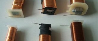
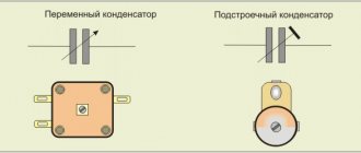
What is an inductor
This element is also called a choke. This is an insulated wire rolled into a spiral. Such a spiral is characterized by large inductive and small capacitive parameters.
Important! The inductor prevents the flow of alternating current because it has significant inertia. It prevents any change in the current passing through the turns. It makes no difference whether it increases or decreases.
In this regard, these elements are used in electrical engineering to implement:
- current limiting;
- weakening of beats;
- interference suppression;
- magnetic field formation;
- manufacturing motion sensors.
The choke is part of the oscillatory circuit system in resonance circuits and is used in delay lines.
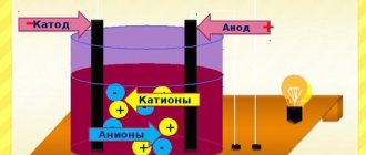
INDUCTANCE
The inductance of a circuit is characterized by the ratio of magnetic flux F to current I
who created this thread:
Cable inductance is measured and normalized in henry, millihenry (10–3 h)
and microhenry (10–6
g)
per 1
km
or 1
m .
Inductance of a single-core cable, as well as external inductance of a coaxial cable
Coaxial Cable Inductance
Total inductance of coaxial cable with copper inner and outer conductors
In the case of a stranded inner conductor, its diameter
The inductance of the inner conductor of a spiral RF delay cable, made in the form of a spiral on top of a core with a magnetic permeability μ c,
Inductance of a two-core unshielded cable (Fig. 2-4)
Inductance of two-core shielded cable (Fig. 2-5)
Inductance of a two-core cable taking into account the magnetic flux inside the cores:
where Q (x) is a coefficient depending on the eddy current coefficient,
and core radius (Table 2-2). As the frequency of the transmitted current increases, the total inductance of the circuit decreases, and the external inductance does not depend on frequency.
Inductance of a two-wire line (Fig. 2-4), when μ =1,
Single wire inductance
With large cross-sections of the cores, as well as at high frequencies, the current is compressed at the periphery of the core, due to which the magnetic field strength inside the core is reduced. Taking this into account, in practice, to determine the inductance of a single wire, they use the formula
Coil design
Inductive elements differ in design:
- type of winding: helical, screw; ring;
- number of layers: single-layer or multi-layer;
- type of insulated wire: single-core, stranded;
- the presence of a frame: framed or frameless (with a small number of turns of thick wire);
- frame geometry: rectangular, square, toroidal;
- the presence of a core: ferrite, carbonyl iron, electrical steel, permalloy (soft magnetic alloy), metal (brass);
- core geometry: rod (open), ring-shaped or w-shaped (closed);
- the ability to change L in narrow intervals (movement of the core relative to the winding).
There are flat coils that are printed and installed on the boards of digital devices.
For your information. Wire winding can be either ordinary (turn to turn) or in bulk. The latter method of laying the wire reduces parasitic capacitance.
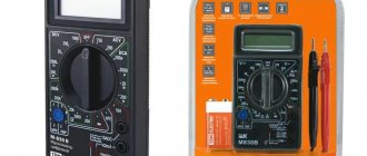
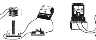
Inductance in AC circuit
For experiments with direct current, the inductor is wound with a thin wire with a large number of turns. This is done so that when voltage is applied to it from a powerful power source, the turns of the coil do not burn out, because when winding turns with a thick wire, the resistance will be small, and the current through it will be large (according to Ohm’s law for direct current I=U/R) and it can burn out. The inductor's resistance to direct current (which can be measured with a multimeter) is called active resistance.
Calculation of coil parameters
We have to consider different options when making calculations. The calculation of inductance depends on the initial data and the specified final parameters.
Calculation of L depending on the given design
If the initial parameters are: w , D frame and the length of the wound wire, then the formula for calculation is:
L = 0.01*D*w2/(l/D) + 0.46,
Where:
- D – frame diameter, cm;
- w – number of turns;
- l – winding length, cm;
- L – inductance, µH.
Equivalent circuit of a real inductor
Each inductor can be represented as an equivalent circuit.
This scheme consists of elements:
- Rw – resistance of the winding with leads;
- L – inductance;
- Cw – parasitic capacitance;
- Rl – loss resistance.
When manufacturing an inductive element, they strive to reduce the amount of loss resistance and parasitic capacitance. When the coil operates at a low frequency, the resistance of its winding Rw is taken into account. Large currents operate at such frequencies.
A correctly calculated inductor will have a high quality factor (180-300) and stable operation under the influence of external conditions (temperature and humidity). Knowing the methods of various winding and pitch manipulation, you can reduce the influence of parasitic factors.