Tesla is a unit of measurement of magnetic induction in the SI system.
The unit of magnetic induction ($\overline{B}$) in the International System of Units (SI) is called tesla (T), named after the Serbian scientist N. Tesla, who successfully worked in the field of radio engineering and electronics.
We determine the unit of measurement of magnetic induction based on Ampere's law. Let us consider a straight conductor with length $l$ through which current $I$ flows. Let this conductor be in a uniform magnetic field $\overline{B}$, and the field induction vector is perpendicular to the conductor. In this case, the magnitude of the Ampere force (${\overline{F}}_A$) acting on the conductor is equal to:
\[F=IBl\ \left(1\right).\]
Let us express the magnetic induction from formula (1), we obtain:
\[B=\frac{F}{I\cdot l}\left(2\right).\]
From expression (2) we see that tesla (a unit of measurement of magnetic induction) is a value corresponding to the magnetic induction of a uniform magnetic field acting on each meter of a straight conductor located in a magnetic field perpendicular to the direction $\overline{B}$, with a force one Newton, with a current in the conductor of one ampere:
\[\left[B\right]=T=\frac{H}{A\cdot m}.\]
The unit of magnetic induction (tesla) is derived from the International Units (SI) system. Through the basic SI units T, as a unit of measurement of magnetic induction, is expressed, taking into account that:
\[H=\frac{kg\cdot m}{s^2},\]
then we get:
\[\left[B\right]=T=\frac{kg\cdot m}{s^2}\cdot \frac{1}{A\cdot m}=\frac{kg}{A\cdot s^ 2}.\]
Standard SI prefixes can be used with Tl when denoting decimal multiples and submultiples. For example, $kT$ (kilo Tesla), $1kT=1000T$; nT (nano Tesla), $1nT={10}^{-9}T.$
1 T is a fairly large value of magnetic induction, especially when we are talking about a constant magnetic field. Man today has been able to create a constant magnetic field of 100.75 Tesla. The pulsed magnetic field artificially created by people reached an induction value of $2.8\cdot {10}^3T$. The Earth's magnetic field can vary significantly depending on location on the planet; it is on the order of $\approx $10 µT.
Physical meaning of magnetic induction
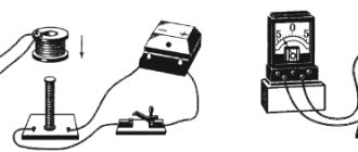
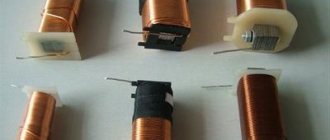
Before moving on to the consideration of the magnetic induction formula, it is necessary to find out what explains the occurrence of the phenomenon itself in the system. The solenoid is not a flat element and includes a spiral of conductor (metal). In the absence of magnetic phenomena affecting it, the electric charges located in the crystal lattice of the spiral material behave statically. When a permanent magnetic element moves in the solenoid, forming a field, charged particles also move under its influence, then an electric current appears in the inductive element, the strength of which is determined by the characteristics of the magnetic and spiral element and how quickly the movement occurs.
Important! Fields having the same orientation are summed up to form a common field. When the movement of charged particles in the solenoid stops, the core ceases to exhibit magnetic characteristics if it is made of soft metal (this rule does not apply to steel products).
Magnetic flux
To characterize the effect of the induction background on a metal circuit, a quantity such as flux is used. It is scalar. In the context of this, it is necessary to find out what induction is measured in. It depends on the number of power lines passing through a unit cross-section of a conducting element. In the international SI system, the unit of measurement is Tesla (T). Hence the name of the device intended for measurements - a teslometer. 1 T is induction that occurs in field space in which a moment of force of 1 N*m affects a circuit with an area of 1 square meter through which a current of 1 ampere flows.
Magnetic flux
A magnetic field
In physics, this term means a certain force field that has a certain effect on moving charged particles, and on other bodies that have a certain magnetic moment. The impact occurs regardless of whether these particles are at rest or in motion. In addition to the magnetic induction vector, an additional characteristic of the field is the vector potential. It is of an alternative nature, but at the same time, in a physical sense, it is inextricably linked with magnetic induction.
For a field operating in an absolute vacuum, the main characteristic is usually not induction, but its intensity, denoted H. However, such a replacement in the sphere of action of the earth’s magnetic field no longer makes much sense, and therefore, in practical experimental measurements and observations of The main characteristic of the magnetic field is still the magnetic induction vector.
In fact, a magnetic field can be defined as a special matter with the help of which interaction occurs between certain charged elementary particles moving at a certain speed.
However, do not confuse magnetic and electromagnetic induction. Electromagnetic induction to a pattern established by the Englishman M. Faraday. The essence of the pattern is the emergence of an electromagnetic force field under the influence of an alternating electric current flowing in a closed conductor circuit. A certain driving force arises in the circuit, which in turn generates an induction current. The magnetic field, along with the electric field, acts as one of the two parts of the electromagnetic field.
The theory of permanent magnets causing induction by their action was developed by the French physicist A-M. Ampere, a unit of electric current power was later named after him. He was the first to establish that the movements of electrons around the center of an atom ultimately generate microscopic, or elementary magnetic fields. He also discovered the property of metal conductors to retain magnetic properties for some time after the influence of the magnetic field on them ceases.
Source
Magnetic field induction. Magnetic induction.
Magnetic induction ( ) is a vector physical quantity that characterizes a magnetic field. For the direction of the magnetic induction vector
accepted:
1. direction from the south pole S to the north pole N of a magnetic needle freely positioned in a magnetic field, or
2. the direction of the positive normal to a closed circuit with current on a flexible suspension, freely installed in a magnetic field. The normal directed towards the movement of the tip of the gimlet (with a right-hand thread), the handle of which is rotated in the direction of the current in the frame, is considered positive.
It is clear that directions 1) and 2) coincide, which was established by Ampere’s experiments.
As for the magnitude of magnetic induction (i.e., its modulus) B, which could characterize the strength of the field, experiments have established that the maximum force F with which the field acts on a current-carrying conductor (placed perpendicular to the magnetic field induction lines) depends on the current strength I in the conductor and on its length Δl (proportional to them). However, the force acting on a current element (of unit length and current strength) depends only on the field itself, i.e., the ratio for a given field is a constant value (similar to the ratio of force to charge for an electric field). This quantity is defined as magnetic induction :
.
The magnetic field induction at a given point is equal to the ratio of the maximum force acting on a current-carrying conductor to the length of the conductor and the current strength in the conductor placed at this point.
The greater the magnetic induction at a given point in the field, the greater the force the field at that point will act on a magnetic needle or a moving electric charge.
The SI unit of magnetic induction is the tesla (T), named after the Croatian electrical engineer Nikola Tesla. As can be seen from the formula, .
Source
Tesla as a unit of measurement:
Tesla is a unit of measurement of magnetic flux density, magnetic field strength and induction in the International System of Units (SI), named after the inventor Nikola Tesla.
Tesla as a unit of measurement has a Russian designation - Tl and an international designation - T.
1 tesla is equal to the induction of such a uniform magnetic field in which a force of 1 newton acts on 1 meter of length of a straight conductor perpendicular to the magnetic induction vector with a current of 1 ampere. In other words, one tesla is equal to the field strength acting on a conductor with a force of one newton per meter of conductor at a current strength for each ampere of current.
Likewise, one tesla represents a magnetic flux density of one weber per square meter of area.
T = kg / (s2 A) = N / (A m) = Wb / m2.
1 T = 1 kg / (1 s2 · 1 A) = 1 N / (1 A · 1 m) = 1 Wb / 1 m2.
Tesla was introduced into the International System of Units by the decision of the XI General Conference on Weights and Measures in 1960, simultaneously with the adoption of the SI system as a whole. In accordance with the SI rules regarding derived units named after scientists, the name of the unit “tesla” is written with a lowercase letter, and its designation is written with a capital letter (T). This spelling of the designation is also preserved in the designations of derived units formed using an adze.
Magnetic induction lines
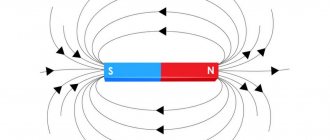
The magnetic field induction itself is characterized by a certain direction, which is represented by lines displayed graphically. These lines are also called magnetic lines, or magnetic field lines. Just like magnetic induction, its lines have their own definition. They are lines to which tangents are drawn at all points of the field. These tangents and the magnetic induction vector coincide with each other.
A uniform magnetic field is distinguished by parallel lines of magnetic induction, coinciding with the direction of the vector at all points.
If the magnetic field is non-uniform, the electromagnetic induction vector will change at each spatial point located around the conductor. Tangents drawn to this vector will result in the creation of concentric circles around the conductor. Thus, in this case, the induction lines will look like expanding circles.
Magnetic induction vector magnitude
By experimenting with the behavior of a frame with current in a magnetic field, one can find that the moment of forces acting on it depends significantly on the following factors:
- on the magnitude of the magnetic field;
- from the area of the frame;
- from the current passing through the frame;
- on the magnetic properties of the substance of the frame itself and the environment around it;
- on the orientation of the frame in the magnetic field.
Thus, the formula for the magnitude of the magnetic induction vector must take into account all these factors. It is convenient to exclude the frame orientation factor from the expression, agreeing to consider only the orientation at which the moment of forces acting on the frame will be maximum. To exclude the magnetic influence in the substance of the frame and around it, we will consider only the frame in a vacuum.
As a result, the left side of the formula will contain the required module, and the right side will contain an expression that includes the moment of forces acting on the frame, the area of the frame and the current strength in it.
It is obvious that the magnetic induction vector is directly proportional to the moment of forces acting on the frame.
With the area of the frame and the current in it, the situation is the opposite. If you increase these values, then, with a constant magnetic field, the moment of force will increase proportionally. This means that the magnetic field induction is inversely proportional to both the area of the frame and the current passing through it.
Finally, we have the formula for the modulus of the magnetic induction vector:
$$B = k {M_{max} \over IS}$$
Where:
- $B$ is the magnitude of the magnetic induction vector;
- $M_{max}$ is the maximum torque acting on the current-carrying frame;
- $I$ is the current in the current loop;
- $S$ is the area of the current-carrying frame;
- $k$ is a proportionality coefficient that depends on the choice of system of units of measurement.
Rice. 3. Magnetic induction.
Dependence of magnetic induction
Electromagnetic induction is absolutely not affected by either the current strength or the length of the conductor. It is directly dependent and connected only with the magnetic field. Thus, when the current strength in the conductor decreases, without changing any other indicators, there is a decrease not in induction, which is directly proportional to the current strength, but in the force with which the magnetic field acts on the conductor. At the same time, the value of the magnetic induction itself remains constant. Thanks to these qualities, electromagnetic induction acts as a quantitative characteristic of the magnetic field.
Magnetic induction is measured in teslas, using the formula: 1 T=1 N/(A*m). The physical dependence of this quantity on various factors can be determined during a simple experiment. It is necessary to take a scale, where a conductor is attached to one side, and weights are located on the other side. The conductor is in a constant electromagnetic field, while its mass and the weight of the weights have the same value.
After balancing the scales, an electric current is passed through the conductor. A magnetic field is formed around it, determined in accordance with the right-hand rule. As a result, interaction between the fields of the permanent magnet and the conductor itself is observed. In this case, the balance of the scales will be disrupted. Due to the flow of current, the side of the scale with the conductor begins to fall. In order to calculate the force of the field on this conductor, you need to balance it using weights. The force of their gravity is calculated using a special formula and will be equal to the force of the magnetic field acting on the current-carrying conductor. The ratio of this force to the length of the conductor and the current strength is a constant value. This quantitative characteristic depends only on the field and is nothing more than the module of the magnetic induction vector.
Magnetic induction
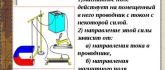
From the physics course in the 11th grade, it is known that the manifestation of a magnetic field consists in the emergence of a force acting on a conductor with current in this magnetic field.
Rice. 1. Conductor with current in a magnetic field.
Thus, to characterize the intensity of the magnetic field, it is advisable to introduce a special force characteristic - magnetic induction.
As a rule, the strength characteristic of a field shows the force with which this field acts on a unit test charge in this field. Force is a vector quantity, which means magnetic induction will also be vector.
The direction of the magnetic induction vector is determined by the gimlet rule or the right hand girth rule (these are equivalent rules, but the right hand rule is clearer and more convenient):
Rice. 2. Right hand rule.
When determining the magnitude of the magnetic induction vector, there are two problems.
- No magnetic charges were detected (although the theory does not prohibit their existence). However, according to Ampere's law, a magnetic field acts on a current-carrying conductor. Therefore, it is necessary to take such a conductor as a test charge in a magnetic field.
- The direction of the resulting force does not coincide with the direction of the current. Therefore, it is necessary to use a frame with current, in which there are currents directed in opposite directions, and to take as the basis for the power characteristic not the force, but the moment of forces acting on this frame.
Taking into account these features of the magnetic field, we can find the magnitude of the magnetic induction vector.
Magnetic induction in the Centimeter-Gram-Second system
In the CGS system, the relationship between induction and voltage in the presence of magnetic material is determined by the following relationship:
B=H+4πI
In this formula, I is the magnetic moment per unit volume of the material (magnetization). In the GHS system, Gaussians (Gs) are used to measure this quantity.
Induction characterizes the field that arises in a substance. Tension determines the parameters of external magnetic fields and magnetic fields in a vacuum. The B value can also be used for external magnetic fields.
In a vacuum, the values of induction and tension are equal (according to the CGS system).
Magnetic induction vector
Magnetic induction lines
All physical parameters are divided into two groups:
- Scalar. These are quantities that have no direction: weight, volume, electrical voltage or current;
- Vector. These are parameters that have a direction: speed, acceleration or inertia.
Magnetic induction is a vector quantity. Its direction coincides with the tangent to the field lines. The shape and direction of the induction lines depend on the conductor.
Direction of magnetic induction
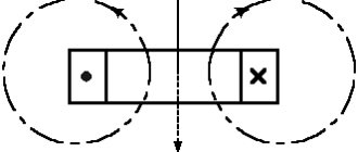
In a straight conductor, the field has the shape of circles, perpendicular to which this conductor runs, and its center coincides with them. The closer to the center, the more lines of force pass through a point in space and the stronger the field. Its direction is determined by the right-hand rule.
Right hand rule
If the wire is rolled into a ring, the field takes on the shape of a torus (donut). If there are many turns and the length exceeds the diameter of the coil, then the lines of force inside it run evenly and parallel. The magnetic properties of this device are similar to a permanent magnet. If the winding is wound on a core made of a material with high magnetic permeability, you will get an electromagnet, the shape of which depends on the core: flat, square or horseshoe-shaped. The direction of the magnetic field passing through such devices can be found using the gimlet rule.
Gimlet rule
Vector module
A vector, in addition to its magnitude, has a modulus, or size, which is an indicator characterizing the numerical value of the parameter. If the magnetic induction itself is denoted B, the directionality is B→, then the module is denoted |B|. This parameter depends on the current and distance to the conductor. To determine the module, the expression has the form |B|=k*(I/r), where:
- k – coefficient. It depends on specific conditions. In a coil with a magnetically permeable core and a large number of turns, the coefficient is greater than in a straight piece of wire;
- I – current strength. The larger it is, the stronger the field it creates and the greater the magnitude of the vector;
- r – distance from the measurement point to the coil or conductor. The closer to the magnet, the denser the field lines are located, and the larger the modulus.
Nearby wires or coils carrying electric current influence each other. The strength of this interaction is found by the formula:
F=|B|*I*l, where l is the length of the wires.
If this formula is transformed according to the laws of algebra to determine the magnetic induction vector, it will take the following form:
|B|=(F/(I*l).
With its help, you can calculate the magnitude of the vector, knowing the strength of mutual influence, the current strength and the length of the wires.
Interesting. This interaction can be seen when the welding current changes in nearby cables.
What is inductance
This term denotes the relationship that is established between the current strength in the conductor (I) and the created magnetic flux (F):
L = Ф/ I.
Given the basic definition, it is not difficult to understand the dependence of inductance on the properties of the environment, which influences the distribution of power lines. The dimensions and configuration of the conductive element have a certain significance.
Inductance is similar to mechanical inertia. Only in this case we are talking about actions with electrical quantities. This coefficient characterizes the ability of the component in question to resist changes in the current passing through it.
