The phenomenon of electromagnetic induction
Electromagnetic induction is the phenomenon of the occurrence of current in a closed conductive circuit when the magnetic flux passing through it changes.
The phenomenon of electromagnetic induction was discovered by M. Faraday.
Faraday's experiments
- Two coils were wound on one non-conducting base: the turns of the first coil were located between the turns of the second. The turns of one coil were closed to a galvanometer, and the second was connected to a current source. When the key was closed and current flowed through the second coil, a current pulse arose in the first. When the switch was opened, a current pulse was also observed, but the current through the galvanometer flowed in the opposite direction.
- The first coil was connected to a current source, the second, connected to a galvanometer, moved relative to it. As the coil approached or moved away, the current was recorded.
- The coil is closed to the galvanometer, and the magnet moves - moves in (extends) - relative to the coil.
Experiments have shown that induced current occurs only when the magnetic induction lines change. The direction of the current will be different when the number of lines increases and when they decrease.
The strength of the induction current depends on the rate of change of the magnetic flux. The field itself may change, or the circuit may move in a non-uniform magnetic field.
Explanations of the occurrence of induction current
Current in a circuit can exist when external forces act on free charges. The work done by these forces to move a single positive charge along a closed loop is equal to the emf. This means that when the number of magnetic lines through the surface limited by the contour changes, an emf appears in it, which is called the induced emf.
Electrons in a stationary conductor can only be driven by an electric field. This electric field is generated by a time-varying magnetic field. It is called an eddy electric field . The concept of a vortex electric field was introduced into physics by the great English physicist J. Maxwell in 1861.
Properties of the vortex electric field:
- source – alternating magnetic field;
- detected by the effect on the charge;
- is not potential;
- the field lines are closed.
The work of this field when moving a single positive charge along a closed circuit is equal to the induced emf in a stationary conductor.
§ 11. Law of electromagnetic induction
Chapter 2. Electromagnetic inductionLet us formulate the law of electromagnetic induction quantitatively. Faraday's experiments showed that the strength of the induced current Ii in a conducting circuit is proportional to the rate of change in the number of magnetic induction lines piercing the surface bounded by this circuit. This statement can be formulated more precisely using the concept of “magnetic flux”.
Magnetic flux can be graphically represented as the number of magnetic induction lines penetrating a surface of area S. The greater the magnetic field induction, the greater the number of magnetic induction lines penetrating this surface. Therefore, the rate of change of this number is nothing more than the rate of change of magnetic flux.
If in a short time Δt the magnetic flux changes by ΔФ, then the rate of change of the magnetic flux is equal to
Therefore, the statement, which follows directly from experience, can be formulated as follows: the strength of the induction current is proportional to the rate of change of the magnetic flux through the surface bounded by the contour:
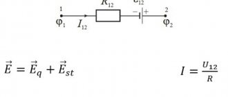
Induction emf. It is known that an electric current appears in a circuit when external forces act on the free charges of a conductor. The quantity numerically equal to the work of these forces when moving a unit positive charge along a closed loop is called electromotive force .
Consequently, when the magnetic flux changes through a surface limited by a contour, extraneous forces appear in the circuit, the action of which is characterized by an emf, called induced emf . It is designated by the letter .
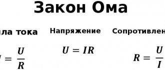
According to Ohm's law for a closed circuit, the resistance of a conductor does not depend on changes in magnetic flux. Consequently, relation (2.3) is valid only because the induced emf is proportional to
Law of electromagnetic induction. The law of electromagnetic induction is formulated specifically for the EMF, and not for the strength of the induced current, since the current strength also depends on the properties of the conductor, and the EMF is determined only by the change in the magnetic flux. According to the law of electromagnetic induction, the induced emf in a closed loop is equal in magnitude to the rate of change of the magnetic flux through the surface bounded by the loop:
How to take into account the direction of the induced current (or the sign of the induced emf) in the law of electromagnetic induction in accordance with Lenz’s rule?
Figure 2.7 shows a closed loop. We will consider the direction of traversing the circuit counterclockwise to be positive. The normal to the contour forms a right screw with the direction of the bypass.
Let the magnetic induction of the external magnetic field be directed along the normal to the contour and increase with time. Then Ф > 0 and > 0. According to Lenz's rule, the induced current creates a magnetic flux Ф' < 0. The induction lines B' of the magnetic field of the induced current are shown in black in Figure 2.7. Consequently, the induced current according to the gimlet rule is directed clockwise (against the direction of the positive circuit) and the induced emf is negative. Therefore, in the formula for the law of electromagnetic induction there should be a “-” sign, indicating that and have different signs:
The induced emf is determined by the rate of change of the magnetic flux.
Questions for the paragraph
1. What is called magnetic flux (magnetic induction flux)?
2. Why is the law of electromagnetic induction formulated for EMF, and not for current?
3. How is the law of electromagnetic induction formulated?
4. Why is there a “—” sign in the formula for the law of electromagnetic induction?
Magnetic flux
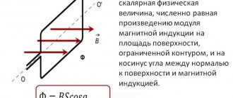
Magnetic flux through the area \( S \) of the contour is called a scalar physical quantity equal to the product of the magnitude of the magnetic induction vector \( B \), the surface area \( S \), penetrated by this flux, and the cosine of the angle \ ( \alpha \) between the direction of the magnetic induction vector and the normal vector (perpendicular to the plane of a given surface):
The designation is \( \Phi \), the SI unit is weber (Wb).
A magnetic flux of 1 weber is created by a uniform magnetic field with an induction of 1 T through a surface of 1 m2 located perpendicular to the magnetic induction vector:
Magnetic flux can be visualized as a value proportional to the number of magnetic lines passing through a given area.
Depending on the angle \( \alpha \) the magnetic flux can be positive (\( \alpha \) < 90°) or negative (\( \alpha \) > 90°). If \( \alpha \) = 90°, then the magnetic flux is 0.
You can change the magnetic flux by changing the area of the circuit, the field induction module, or the location of the circuit in the magnetic field (by rotating it).
In the case of a non-uniform magnetic field and a non-flat contour, the magnetic flux is found as the sum of the magnetic fluxes penetrating the area of each of the sections into which a given surface can be divided.
Faraday's law of electromagnetic induction
Law of electromagnetic induction (Faraday's law):
The induced emf in a closed loop is equal and opposite in sign to the rate of change of the magnetic flux through the surface bounded by the loop:
The “–” sign in the formula allows you to take into account the direction of the induction current. The induced current in a closed circuit always has such a direction that the magnetic flux of the field created by this current through the surface bounded by the circuit would reduce those changes in the field that caused the appearance of the induced current.
If the circuit consists of \( N \) turns, then the induced emf:
The strength of the induction current in a closed conductive circuit with resistance \( R \):
When a conductor of length \( l \) moves with a speed \( v \) in a constant uniform magnetic field with induction \( \vec{B} \) the emf of electromagnetic induction is equal to:
where \( \alpha \) is the angle between the vectors \( \vec{B} \) and \( \vec{v} \).
The occurrence of induced emf in a conductor moving in a magnetic field is explained by the action of the Lorentz force on free charges in moving conductors. The Lorentz force plays the role of an external force in this case.
A conductor moving in a magnetic field through which an induced current flows experiences magnetic braking. The total work done by the Lorentz force is zero.
The amount of heat in the circuit is released either due to the work of an external force, which maintains the speed of the conductor unchanged, or due to a decrease in the kinetic energy of the conductor.
Important! A change in the magnetic flux penetrating a closed circuit can occur for two reasons:
- the magnetic flux changes due to the movement of the circuit or its parts in a time-constant magnetic field. This is the case when conductors, and with them free charge carriers, move in a magnetic field;
- The second reason for the change in the magnetic flux penetrating the circuit is the change in time of the magnetic field when the circuit is stationary. In this case, the occurrence of induced emf can no longer be explained by the action of the Lorentz force. The phenomenon of electromagnetic induction in stationary conductors, which occurs when the surrounding magnetic field changes, is also described by Faraday's formula.
Thus, the phenomena of induction in moving and stationary conductors proceed in the same way, but the physical reason for the occurrence of induction current turns out to be different in these two cases:
- in the case of moving conductors, the induced emf is due to the Lorentz force;
- in the case of stationary conductors, the induced emf is a consequence of the action on free charges of the vortex electric field that occurs when the magnetic field changes.
Electromagnetic induction. Lenz's rule
The phenomenon of electromagnetic induction was discovered by the outstanding English physicist M. Faraday in 1831. It consists in the occurrence of an electric current in a closed conducting circuit when the magnetic flux penetrating the circuit changes over time.
The magnetic flux Φ through the area S of the circuit is the quantity
| Φ = B S cos α, |
where B is the magnitude of the magnetic induction vector, α is the angle between the vector and the normal to the contour plane (Fig. 1.20.1).
| Figure 1.20.1. Magnetic flux through a closed loop. The normal direction and the selected positive direction of the contour traversal are related by the right gimlet rule |
The definition of magnetic flux is easy to generalize to the case of a non-uniform magnetic field and a non-planar circuit. The SI unit of magnetic flux is called Weber (Wb). A magnetic flux equal to 1 Wb is created by a magnetic field with an induction of 1 T, penetrating in the normal direction a flat contour with an area of 1 m2:
| 1 Wb = 1 T · 1 m2. |
Faraday experimentally established that when the magnetic flux changes in a conducting circuit, an induced emf arises equal to the rate of change of the magnetic flux through the surface bounded by the circuit, taken with a minus sign:
This formula is called Faraday's law .
Experience shows that the induction current excited in a closed loop when the magnetic flux changes is always directed in such a way that the magnetic field it creates prevents the change in the magnetic flux that causes the induction current. This statement, formulated in 1833, is called Lenz's rule .
Rice. 1.20.2 illustrates Lenz’s rule using the example of a stationary conducting circuit that is in a uniform magnetic field, the induction modulus of which increases with time.
| Figure 1.20.2. Illustration of Lenz's rule. In this example, a. Induction current Iind flows towards the selected positive direction of circuit bypass |
Lenz's rule reflects the experimental fact that and always have opposite signs (the minus sign in Faraday's formula). Lenz's rule has a deep physical meaning - it expresses the law of conservation of energy.
A change in the magnetic flux penetrating a closed circuit can occur for two reasons.
1. The magnetic flux changes due to the movement of the circuit or its parts in a time-constant magnetic field. This is the case when conductors, and with them free charge carriers, move in a magnetic field. The occurrence of induced emf is explained by the action of the Lorentz force on free charges in moving conductors. The Lorentz force plays the role of an external force in this case.
Let us consider, as an example, the occurrence of an induced emf in a rectangular circuit placed in a uniform magnetic field perpendicular to the plane of the circuit. Let one of the sides of a contour of length l slide with speed along the other two sides (Fig. 1.20.3).
| Figure 1.20.3. The occurrence of induced emf in a moving conductor. The component of the Lorentz force acting on a free electron is indicated |
The Lorentz force acts on the free charges in this section of the circuit. One of the components of this force, associated with the transfer speed of charges, is directed along the conductor. This component is shown in Fig. 1.20.3. She plays the role of an outside force. Its module is equal
| FL = eυB |
The work done by the force FL on the path l is equal to
| A = FL · l = eυBl. |
According to the definition of EMF
In other stationary parts of the circuit, the external force is zero. The ratio for ind can be given the usual form. During time Δt, the contour area changes by ΔS = lυΔt. The change in magnetic flux during this time is equal to ΔΦ = BlυΔt. Hence,
In order to establish the sign in the formula connecting and, you need to select the normal direction and the positive direction of traversing the contour, consistent with each other according to the rule of the right gimlet, as is done in Fig. 1.20.1 and 1.20.2. If this is done, then it is easy to arrive at Faraday's formula.
If the resistance of the entire circuit is equal to R, then an induction current equal to . During the time Δt, Joule heat will be released at the resistance R
The question arises: where does this energy come from, since the Lorentz force does no work! This paradox arose because we took into account the work of only one component of the Lorentz force. When an induction current flows through a conductor located in a magnetic field, another component of the Lorentz force, associated with the relative speed of movement of the charges along the conductor, acts on the free charges. This component is responsible for the appearance of ampere power. For the case shown in Fig. 1.20.3, the ampere force modulus is equal to FA = IB l. Ampere's force is directed towards the movement of the conductor; therefore it does negative mechanical work. During the time Δt this work Amech is equal to
A conductor moving in a magnetic field through which an induced current flows experiences magnetic braking . The total work done by the Lorentz force is zero . Joule heat in the circuit is released either due to the work of an external force, which maintains the speed of the conductor unchanged, or due to a decrease in the kinetic energy of the conductor.
2. The second reason for the change in the magnetic flux penetrating the circuit is the change in time of the magnetic field when the circuit is stationary. In this case, the occurrence of induced emf can no longer be explained by the action of the Lorentz force. Electrons in a stationary conductor can only be driven by an electric field. This electric field is generated by a time-varying magnetic field. The work of this field when moving a single positive charge along a closed circuit is equal to the induced emf in a stationary conductor. Therefore, the electric field generated by a changing magnetic field is not potential . It is called an eddy electric field . The concept of a vortex electric field was introduced into physics by the great English physicist James Maxwell in 1861.
The phenomenon of electromagnetic induction in stationary conductors, which occurs when the surrounding magnetic field changes, is also described by Faraday's formula. Thus, the phenomena of induction in moving and stationary conductors proceed in the same way , but the physical cause of the occurrence of induced current turns out to be different in these two cases: in the case of moving conductors, the induction emf is due to the Lorentz force; in the case of stationary conductors, the induced emf is a consequence of the action on free charges of the vortex electric field that occurs when the magnetic field changes.
| Model. Electromagnetic induction |
| Model. Faraday's experiments |
| Model. Alternator |
Lenz's rule
The direction of the induction current is determined by Lenz's rule : the induction current excited in a closed loop when the magnetic flux changes is always directed so that the magnetic field it creates prevents the change in the magnetic flux causing the induction current.
Algorithm for solving problems using Lenz's rule:
- determine the direction of the magnetic induction lines of the external magnetic field;
- find out how magnetic flux changes;
- determine the direction of the magnetic induction lines of the magnetic field of the induced current: if the magnetic flux decreases, then they are co-directed with the lines of the external magnetic field; if the magnetic flux increases, it is opposite to the direction of the magnetic induction lines of the external field;
- according to the gimlet rule, knowing the direction of the induction lines of the magnetic field of the induction current, determine the direction of the induction current.
Lenz's rule has a deep physical meaning - it expresses the law of conservation of energy.
INFOPHYS is my world...
Lenz's rule: an induced current excited in a closed loop when a magnetic flux changes always counteracts the change in magnetic flux that causes it.
Faraday's law: The induced emf is equal to the rate of change of the magnetic flux through the surface bounded by the contour.
The minus sign in the formula reflects Lenz's rule .
In 1833, Lenz experimentally proved a statement called Lenz's rule: the induced current excited in a closed loop when the magnetic flux changes is always directed so that the magnetic field it creates prevents the change in the magnetic flux causing the induced current.
With increasing magnetic flux Ф>0, and εind<0, i.e. An induced emf produces a current in a direction in which its magnetic field reduces the magnetic flux through the circuit.
When the magnetic flux decreases, Ф<0, and εind>0, i.e. the magnetic field of the induced current increases the decreasing magnetic flux through the circuit.
Lenz's rule has a deep physical meaning - it expresses the law of conservation of energy : if the magnetic field through the circuit increases, then the current in the circuit is directed so that its magnetic field is directed against the external one, and if the external magnetic field through the circuit decreases, then the current is directed so that that its magnetic field maintains this decreasing magnetic field.
The induced emf depends on various reasons. If you push a strong magnet into the coil once, and a weak one another time, then the readings of the device in the first case will be higher. They will also be higher when the magnet moves quickly. In each of the experiments carried out in this work, the direction of the induction current is determined by Lenz’s rule. The procedure for determining the direction of the induction current is shown in the figure.
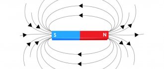
In the figure, the magnetic field lines of a permanent magnet and the magnetic field lines of the induced current are indicated in blue. The magnetic field lines are always directed from N to S - from the north pole to the south pole of the magnet.
According to Lenz's rule, the induced electric current in a conductor, arising when the magnetic flux changes, is directed in such a way that its magnetic field counteracts the change in the magnetic flux. Therefore, in the coil the direction of the magnetic field lines is opposite to the force lines of the permanent magnet, because the magnet moves towards the coil. We find the direction of the current using the gimlet rule: if a gimlet (with a right-hand thread) is screwed in so that its translational movement coincides with the direction of the induction lines in the coil, then the direction of rotation of the gimlet handle coincides with the direction of the induction current.
Therefore, the current through the milliammeter flows from left to right, as shown in the figure by the red arrow. In the case when the magnet moves away from the coil, the magnetic field lines of the induced current will coincide in direction with the field lines of the permanent magnet, and the current will flow from right to left.
Self-induction
Self-induction is the phenomenon of the occurrence of induced emf in a conductor as a result of a change in current in it.
When the current in the coil changes, the magnetic flux created by this current changes. A change in the magnetic flux passing through the coil should cause the appearance of an induced emf in the coil.
In accordance with Lenz's rule, the self-inductive emf prevents the current from increasing when the circuit is turned on and the current from decreasing when the circuit is turned off.
This leads to the fact that when a circuit is closed in which there is a current source with a constant EMF, the current strength is established after some time.
When the source is turned off, the current also does not stop instantly. The self-inductive emf that arises in this case may exceed the source emf.
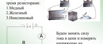
The phenomenon of self-induction can be observed by assembling an electrical circuit from a coil with high inductance, a resistor, two identical incandescent lamps and a current source. The resistor must have the same electrical resistance as the coil wire.
Experience shows that when the circuit is closed, an electric lamp connected in series with a coil lights up somewhat later than a lamp connected in series with a resistor. The increase in current in the coil circuit during closure is prevented by the self-induction emf, which occurs when the magnetic flux in the coil increases.
When the power source is turned off, both lamps flash. In this case, the current in the circuit is maintained by the self-induction emf that occurs when the magnetic flux in the coil decreases.
Self-inductive emf \( \varepsilon_{is} \), arising in a coil with inductance \( L \), according to the law of electromagnetic induction is equal to:
The self-inductive emf is directly proportional to the inductance of the coil and the rate of change of current in the coil.
Inductance
Electric current passing through a conductor creates a magnetic field around it. The magnetic flux \( \Phi \) through the loop of this conductor is proportional to the induction modulus \( \vec{B} \) of the magnetic field inside the loop, and the magnetic field induction, in turn, is proportional to the current strength in the conductor.
Therefore, the magnetic flux through the loop is directly proportional to the current in the loop:
Inductance is a coefficient of proportionality \( L \) between the current strength \( I \) in the circuit and the magnetic flux \( \Phi \) created by this current:
Inductance depends on the size and shape of the conductor, on the magnetic properties of the environment in which the conductor is located.
The SI unit of inductance is henry (H). The inductance of the circuit is 1 henry if, at a direct current of 1 ampere, the magnetic flux through the circuit is 1 weber:
We can give a second definition of the unit of inductance: an element of an electrical circuit has an inductance of 1 H if, with a uniform change in the current in the circuit by 1 ampere in 1 s, a self-inductive emf of 1 volt occurs in it.
Law of Electromagnetic Induction
The electromotive force induced in a conducting circuit is equal to the rate of change of the magnetic flux coupling to that circuit.
In a coil that has several turns, the total emf depends on the number of turns n:
But in the general case, the EMF formula with general flux linkage is used:
The EMF excited in the circuit creates a current. The simplest example of the appearance of current in a conductor is a coil through which a permanent magnet passes. The direction of the induced current can be determined using Lenz's rule .
Basic formulas of the section “Electromagnetic induction”
Algorithm for solving problems on the topic “Electromagnetic induction”:
1. Carefully read the conditions of the problem. Establish the reasons for the change in the magnetic flux penetrating the circuit.
2. Write down the formula:
- law of electromagnetic induction;
- induced emf in a moving conductor, if the problem considers a progressively moving conductor; If the problem considers an electrical circuit containing a current source and an induced emf arising in one of the sections, caused by the movement of a conductor in a magnetic field, then you first need to determine the magnitude and direction of the induced emf. After this, the problem is solved by analogy with problems for calculating a direct current circuit with several sources.
3. Write down an expression for the change in magnetic flux and substitute it into the formula for the law of electromagnetic induction.
4. Write down all additional conditions mathematically (most often these are the formulas of Ohm’s law for a complete circuit, Ampere force or Lorentz force, formulas of kinematics and dynamics).
5. Solve the resulting system of equations for the desired value.
6. Check the solution.
Electromagnetic oscillations and waves →
← Magnetic field
Electromagnetic induction
3.1 (62.63%) 38 votes