Wooden supports
They are usually made from pine logs with the bark removed. For power lines with supply voltages up to 1000 V, it is also possible to use other tree species, for example, fir, oak, cedar, spruce, and larch. Logs that will subsequently become power line supports must meet certain technical requirements. The natural taper of the trunk, in other words, the change in its diameter from the thick lower end (butt) to the upper cut should not exceed 8 mm per 1 meter of log length. The diameter of the log on the upper cut for lines with voltage up to 1000 V is taken to be at least 12 cm, for lines with voltage above 1000 V, but not higher than 35 kV - 16 cm, and for lines with higher voltage at least 18 cm.
Wooden supports can be used for the construction of overhead lines with a voltage not exceeding 110 kV inclusive. Wooden supports are most widely used in overhead lines with voltages up to 1000 V, as well as in communication lines. The advantage of wooden supports is their relatively low cost and ease of manufacture. However, there is a minus, a significant minus - they are susceptible to rotting and the service life of pine supports is about 4-5 years. To protect wood from rotting, it is impregnated with special antiseptics against rotting, for example anthracene or creosote oil. Those parts that will be dug into the ground, as well as cutting ends, braces and traverses, lend themselves to especially careful processing. Thanks to antiseptics, the service life increases by about 2-3 times. For the same purpose, quite often the legs of a wooden electrical support are made of two parts - the main stand and the chair (stepchild):
Where – 1) the main stand, and 2) a chair (stepchild)
If the lower part is severely rotted, it is enough to replace only the stepson.
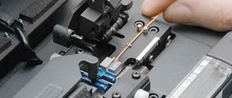
Why are the wires humming?
0
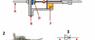
What about the wires? They hang high above the ground and from a distance look like thick monolithic cables. In fact, high-voltage wires are twisted from wire. A common and widely used wire has a steel core, which provides structural strength and is surrounded by aluminum wire, the so-called outer layers, through which the current load is transmitted. There is a lubricant between the steel and aluminum. It is needed in order to reduce friction between steel and aluminum - materials that have different coefficients of thermal expansion. But since aluminum wire has a round cross-section, the turns do not fit tightly against each other, and the surface of the wire has a pronounced relief. This deficiency has two consequences. Firstly, moisture penetrates into the cracks between the turns and washes away the lubricant. Friction increases and conditions for corrosion are created. As a result, the service life of such a wire is no more than 12 years. To extend the service life, repair cuffs are sometimes put on the wire, which can also cause problems (more on this below). In addition, this wire design helps create a clearly visible hum near the overhead line. It occurs due to the fact that an alternating voltage of 50 Hz creates an alternating magnetic field, which causes the individual cores in the wire to vibrate, which causes them to collide with each other, and we hear a characteristic hum. In EU countries, such noise is considered acoustic pollution and is dealt with. Now such a struggle has begun among us.
0
“We now want to replace the old wires with wires of a new design that we are developing,” says a representative of Rosseti PJSC. — These are also steel-aluminum wires, but the wire used there is not round, but rather trapezoidal. The layering is dense, and the surface of the wire is smooth, without cracks. Moisture almost cannot get inside, the lubricant is not washed out, the core does not rust, and the service life of such a wire is approaching thirty years. Wires of a similar design are already used in countries such as Finland and Austria. There are lines with new wires in Russia - in the Kaluga region. This is the Orbit-Sputnik line, 37 km long. Moreover, the wires there have not just a smooth surface, but also a different core. It is made not of steel, but of fiberglass. This wire is lighter, but more tensile strength than conventional steel-aluminum wire.”
0
However, the most recent design achievement in this area can be considered the wire created by the American concern 3M. In these wires, the load-bearing capacity is provided only by conductive layers. There is no core, but the layers themselves are reinforced with aluminum oxide, which achieves high strength. This wire has excellent load-bearing capacity, and with standard supports, due to its strength and low weight, it can withstand spans up to 700 m long (standard 250-300 m). In addition, the wire is very resistant to thermal stress, which determines its use in the southern states of the USA and, for example, in Italy. However, the 3M wire has one significant drawback - the price is too high.
Metal supports
Plus - durable and reliable in operation. Minus - a large consumption of metal is required, which entails a significant increase in cost (compared to wooden ones). Metal supports of overhead power lines are used, as a rule, at voltages from 110 kV, since the operation of metal supports involves high costs for performing very labor-intensive and expensive work on periodic painting, which protects against corrosion.
Classification by material
Depending on what they are made of, they can be wooden, metal or reinforced concrete.
- Wooden supports are made from coniferous round timber. Length - 5-13 meters, diameter at the top 12-26 cm, primary area of use - rural power lines. Since wood is susceptible to rotting and exposure to aggressive weather factors, it is treated with antiseptic compounds. Coal and anthracene oils and donalite are recognized as the best. When using them, the service life of wooden supports is extended to 25-30 years, subject to additional antiseptic treatment after 15-17 years by installing special bandages.
- Reinforced concrete ones are more durable (their service life is 2 times longer than their wooden counterparts). Increasing the strength of reinforced concrete is achieved by using vibration technologies or centrifugation during production. On power lines with a design voltage below 35 kV, vibrated concrete supports are used, from 35 to 110 kV - from vibrated concrete or centrifuged, from 110 to 500 kV - only centrifuged.
- Metal supports are used on high-voltage lines. They are a three-dimensional lattice structure installed on a reinforced concrete foundation for greater strength. In order to protect against corrosion, the metal is treated with special compounds, which extends its service life.
Support structures also differ in their purpose.
Reinforced concrete supports
In the industrial manufacturing process, they are the most optimal option for overhead lines both up to 1000 V and above 1000 V. The use of reinforced concrete supports dramatically reduces operating costs, since they practically do not require repairs. Currently, almost everywhere, reinforced concrete supports are used in the construction of overhead lines of 6-10 kV and up to 110 kV. They are especially widespread in urban networks up to and above 1000 V. Reinforced concrete supports can be made either monolithic (cast) or in the form of assemblies, which are assembled directly at the installation site. Their strength depends on the method of concrete compaction, of which there are two - centrifugation and vibration. When using the centrifugation method, a good density of concrete is obtained, which subsequently has a good effect on the finished product.
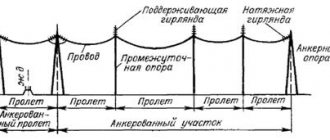
On overhead power lines, special anchor, corner, end, and intermediate supports are used.
Anchor supports
Their purpose is to rigidly secure wires and lines to them. The location for their installation is determined by the project. By design, the anchor support must be strong, since if a wire breaks on one side, it must withstand the mechanical load of the wires on the other side of the line.
Anchor spans are the distance between anchor supports. On straight sections (depending on the cross-section of the wires), anchor spans are up to 10 km long.
Classification of power transmission line supports by purpose
Depending on what functions the supports perform, they can be:
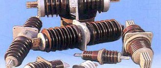
- intermediate - used exclusively to support current-carrying lines. They are not designed for tensile forces, so the cable is attached to them using suspension or pin insulators that reduce tension. In modern power lines, the number of intermediate supports ranges from 80 to 90% of the total;
- anchor - designed for rigid fastening of the cable to avoid breaks, destruction and emergency situations. The cable is attached to them through several insulators. Anchor structures are installed, for example, on long straight sections every 5 km. If ice thicker than 10 mm thick forms in the region in winter, then anchor supports are placed every 3 km;
- angular - designed for areas where power lines change direction at a certain angle. If the angle of rotation is less than 20°, then the fastening is performed according to the intermediate type. At angles from 20 to 90 degrees - rigid fastening like an anchor;
- end - installed upon completion of the power line. They are a type of anchor, as they constantly operate in cable tension mode.
Special supports are also widely used (transitional ones through gorges and rivers, branch ones when installing branches from the main power line, transpositional ones when it is necessary to change the location of the cable). They have a special design, large height and are made according to special projects.
Special supports
They are electric poles of increased height and are used at intersections of power transmission lines with highways and railways, rivers, intersections between power lines themselves, and in other cases when the standard height of electric poles is not enough to ensure the required distance to the wires. Intermediate electrical supports for lines with voltages up to 10 kV are made single-post (candle-shaped). In low-voltage networks, single-post supports perform the functions of corner or end supports, and are also equipped additionally with guy wires attached to the side opposite to the tension of the wires, or with struts (supports) that are installed on the side of the tension of the wires:
For lines with a voltage of 6-10 kV, electrical supports are made A-shaped:
Air lines are also characterized by their main dimensions and dimensions.
Overhead line dimension is the vertical distance from the lowest point of the wire to the ground or water.
The sag is the distance between the imaginary straight line between the wire attachment points on the support and the lowest point of the wire in the span:
All dimensions of power lines are strictly regulated by the PUE and directly depend on the value of the supply voltage, as well as the terrain through which the route passes.
The PUE also regulates other dimensions when crossing and approaching power lines, both among themselves and between communication lines, highways and railways, overhead pipelines, and cable cars.
To check the designed power line to the requirements of the PUE, mechanical strength calculations are performed, the methods of which are given in special courses on electrical networks.