The bracket is selected depending on the type of lamps and their number on the support. There are many types of brackets; you can order an individual one for a specific particular case, but as a rule, standard solutions are used. No matter how the bracket is named (there are many options for marking), it will indicate the height, reach, number of arms, the diameter of the entire pipe or only the part that goes into the support, the type of bracket (plug-in or attached with clamps, usually for reinforced concrete supports like NE), as well as degrees of horn elevation and between horns. Typical sizes are presented in the section. The coating is hot-dip galvanized or powder painted according to the RAL catalogue.
Go to the section Brackets for lamps
INSTALLATION OF METAL LIGHTING SUPPORTS
The method of installing lighting poles depends on the characteristics of the soil and the type of foundation.
Difference between straight and flanged supports
Straight-up supports are secured by pouring concrete at the base of the support, which eliminates the possibility of dismantling the support for subsequent installation in another location. Upright lighting poles are installed in the pit, followed by pouring concrete. The depth of the pit is on average 2-2.5 meters. Flange supports at the bottom have a special round or square flange with holes for bolts. The flange is attached to the foundation embedded part with anchor bolts. Only the embedded parts are concreted in the ground, which allows the support to be carefully dismantled for transfer to another installation location. Depending on the characteristics of the soil, straight, remote or cantilever foundation parts are used for mounting flange supports. The lighting pole plant manufactures and supplies lighting poles and masts with the components necessary for the installation and operation of the poles.
Types of foundation embedded parts
- Anchor embedded parts
- Tubular type embedded parts
- External tubular type embedded parts
- Tubular type cantilever embedded parts
Power and non-power lighting supports
The difference between power and non-power lighting supports lies in the method of supplying and fastening power cables and additional structures. It is possible to suspend the cable from the power support or lay it underground. Power supports also allow the mounting of billboards and other massive structures, as they are able to withstand greater weight. Electrification is supplied to a non-power pole only underground; the cable is pulled at a depth of more than 80 cm. Near highways, the depth should be higher than 125 cm.
Stages of installation work
Correct installation of lighting poles affects safety and service life. Installation and connection of lighting poles to the network can only be carried out by specialists who have access to electrical installation work. Preparatory stages:
1. Preparation of project documentation, which indicates all the parameters of the electrical wire to be laid, its cross-section, type of lighting source, as well as the main technical details. The design of installation sites for supports must be carried out by a design organization that has a license to design foundations and is authorized to do so by the customer. The power of the foundation part of the support must comply with the requirements of SNiP 2.02.01-83 “Foundations of buildings and structures”. 2. Obtaining permission to carry out installation work 3. Obtaining diagrams of the location of communications in the installation area 4. When installing lighting poles underground for electrical cables, the territory is marked, the location of the cables and lighting poles is indicated in accordance with the project and as-built diagram.
Technological maps and SNiP
Routing
Stages of installation of upright lighting poles:
1. Clear the area and mark the installation sites. Using a level, we mark the control points where the lighting supports will be located.
2. Using a well drill, we create a pit in the ground (depending on the size of the support, but not less than 1 meter). The diameter of the hole should be 10 cm larger than the diameter of the support.
3. At the bottom we form a “pillow” of sand and gravel.
4. When installing the supply cable using the underground method (if the cable is installed using the overhead method, go to step 14) - using special equipment or manually, we dig a trench for laying a cable line for supplying electricity, the depth of the trench must be at least 80 cm, and near highways - over 125 cm.
5. If the cable is not armored, then it is necessary to protect it with specialized electrical pipes. The best option is to use double-walled corrugated pipes of the appropriate cross-section and length.
6. A layer of sand or fine clean soil without inclusions in a layer of at least 10 cm is poured into the trench and compacted.
7. Lay the cable in the pipe.
8. We fill the cable line and tamp it with fine soil or sand, in a layer of at least 10 cm.
9. At a distance of 25 cm from the cable, we lay a counter signal.
10. Next, the trench is finally backfilled, taking into account further shrinkage of the earth after rain, and a final check for the absence of gaps.
11. Places where cables enter the concrete foundation must be protected by electrical pipes along the entire height of the concrete foundation.
12. The length of the power cable in the ground part must be sufficient for free connection to the shield, which is installed in the niche of the support.
13. Place a plastic casing for laying the power cable.
14. Place the base of the lighting support in the niche, center it and fix it using temporary spacers.
15. Fill the pit with concrete mortar (class min B-20) and dismantle the fixing spacers after it has dried.
16. The surface of the concrete must be accurately leveled horizontally to ensure that the base of the support fits.
ATTENTION: Only precise leveling of the concrete will guarantee correct vertical installation of the support.
17. Cover the upper part of the hardened concrete foundation with a layer of bitumen.
18. We connect the pre-wired power cables in the input panel.
19. Connect the grounding wire to the grounding junction.
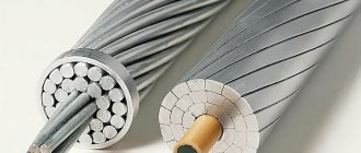
Materials for supporting structures for lanterns
All lantern bases are in the form of a pole or mast, which can be made from:
- metal;
- reinforced concrete;
- composite materials;
Not only the quality of lighting in the dark, but also the safety of people depends on the strength of the foundations. Designs for street lamps must meet strict technical requirements. The installation of such structures should always be carried out by experienced specialists who will ensure their secure fixation. The technology for fastening the bases is determined by the material from which they are made.
Reinforced concrete structures are considered the most affordable. Reinforcement gives more strength to concrete. But such products do not always meet the aesthetic requirements for urban landscapes. Therefore, cities often install metal lighting poles, which are made from steel or aluminum. From metal you can create various shapes of bases that will not spoil the appearance of the lantern.
Structures made from composite materials are distinguished by the ability to create any shape for the base. They are not afraid of aggressive street influences and can be made in any shape. Such poles weigh little, so they do not pose a danger to pedestrians. But their service life is shorter than that of their metal counterparts and is no more than 50 years. In addition, composite materials are expensive and have good flammability, which is very dangerous if a car collides with a street lamp.
WHY CHOOSE US?
Possible shipment on the day of payment
Delivery in original packaging
Status Tracking
order
Deliveries to more than 80 cities in Russia and the CIS
Stages of installation of flanged lighting supports:
1. Clear the area and mark the installation sites. Using a level, we mark the control points where the lighting supports will be located.
2. Using a well drill, we create a pit in the ground (depending on the size of the support, but not less than 1 meter). The diameter of the hole should be 10 cm larger than the diameter of the support.
3. When installing the supply cable using the underground method (if the cable is installed by air, go to point 12, skip point 13) - using special equipment or manually, dig a trench for laying a cable line for supplying electricity, the depth of the trench must be at least 80 cm , and near highways - over 125 cm.
4. If the cable is not armored, then it is necessary to protect it with specialized electrical pipes. The best option is to use double-walled corrugated pipes of the appropriate cross-section and length.
5. Pour into the trench and compact a layer of sand or fine clean soil without inclusions in a layer of at least 10 cm.
6. Lay the cable in the pipe.
7. We fill the cable line and compact it with fine soil or sand with a layer of at least 10 cm.
8. At a distance of 25 cm from the cable, we lay a counter signal.
9. Next, the trench is finally backfilled, taking into account further shrinkage of the earth after rain, and a final check for the absence of gaps.
10. The places where the cable enters the flange embedded part must be protected by electrical pipes along the entire height of the concrete foundation.
11. The length of the power cable in the ground part must be sufficient to freely connect it to the shield, which is installed in the niche of the support.
12. We pass the cable through a polyethylene pipe and bring it out above the flange of the embedded part.
13. Place the foundation part in a prepared pit, which should be 10 cm larger than its size.
14. We install at least three wooden wedge spacers between the barrel of the embedded part and the walls of the well, controlling the horizontal plane of the flange. Deviation from the horizontal plane of the flange is allowed no more than 1:50.
15. Place a plastic casing for laying the power cable.
16. Fill the pit with concrete mortar (class min B-20) to fix the foundation embedded part to the level of the ground surface. Cavities and voids are not allowed.
17. The surface of the concrete must be accurately leveled horizontally to ensure that the base of the support fits.
ATTENTION: Only precise leveling of the concrete will guarantee correct vertical installation of the support.
18. Cover the upper part of the hardened concrete foundation with a layer of bitumen.
The support is installed only after the concrete base has hardened, that is, no earlier than three days.
19. Place the lighting support on the anchor studs or bolts of the pre-poured foundation.
The use of metal cables is not permitted.
20. Connect the power cables to the support niche. Using a level, align the lower support nuts on the anchor bolts horizontally.
21. Install a washer on each of the threaded rods and tighten the nuts. We check the vertical installation of the support; if necessary, loosen the upper nuts and rotate the lower nuts until a deviation from the vertical is no more than 0.5 degrees.
This fastening method allows you to adjust the position of the support if the embedded part has shifted due to soil shrinkage or other factors.
22. We connect the pre-wired power cables in the input panel, then close the niche cover by tightening the bolts.
23. Connect the grounding wire to the grounding junction.
Installation of supports on foundations that are not completely covered with soil is prohibited.
The current list of items in stock in PDF format is available here
Video of installation of lighting poles
Attention
When carrying out work on the lighting system, such as dusting or painting, that does not require supervision by qualified personnel, remember:
- A lighting device is an electrical installation that is energized. Before starting work, turn off the voltage from the control panel and unscrew the usual fuses.
- Lever type fuses must be installed in the off position.
- Using an indicator screwdriver, check for voltage in the line.
- Even if you are absolutely sure that the circuit is de-energized, NEVER touch two or more wires at the same time.
- Related Posts
- Selecting a current-limiting resistor for an LED
- LED dimmer 220V
- Phosphor: composition, purpose and application
Anchor embedded parts
The products consist of several pins distributed in a circle, or four – installed in the corners of a square. In both cases, individual elements are fastened into a single structure by conductors located in the upper and lower parts of the embedded part. Using mounting holes, they are strung onto pins with a diameter of 30-42mm.
The total diameter of round anchor products intended for installation of a support or mast is determined by a conventional circle connecting the centers of the studs. The size ranges from 540 to 1500mm. For square elements, this indicator indicates the distance between two corner pins.
The support thrust bearing is mounted on the ends of the studs protruding from the concrete mass, which are actually anchors. Fixation is carried out using fasteners provided for by the work technology. Typically, anchor parts require nuts and washers that thread onto studs.
The symbol for the anchor element for supports includes:
- abbreviation details;
- diameter and number of studs;
- the diameter of the holes on the jig along the circumference or the distance between the corner slots;
- length of the embedded part;
- symbol of the protective layer (ХЦ – cold galvanizing, b – bitumen mastic).