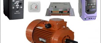
What is an asynchronous motor?
AC electric motors have found quite wide application in various spheres of our life, in hoisting, processing, and measuring equipment. They are used to convert electrical energy that comes from the network into mechanical energy of a rotating shaft. Most often, asynchronous AC converters are used. In them, the rotation speed of the rotor and stator is different. A structural air gap is provided between these active elements.
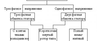
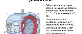
Both the stator and the rotor have a rigid core made of electrical steel (composited type, made of plates), acting as a magnetic circuit, as well as a winding that fits into the structural grooves of the core. It is the way in which the rotor winding is organized or laid out that is the key criterion for classifying these machines.
Squirrel-cage motors (SCR)
Here, a winding is used in the form of aluminum, copper or brass rods, which are inserted into the grooves of the core and closed on both sides by disks (rings). The type of connection of these elements depends on the engine power: for small values, the method of joint casting of disks and rods is used, and for large values, separate production is used, followed by welding to each other. The stator winding is connected using delta or star circuits.
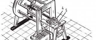
Wound rotor motors
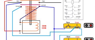
The three-phase rotor winding is connected to the network via slip rings on the main shaft and brushes. The “star” scheme is taken as the basis. The figure below shows a typical design of such an engine.
Operating principle and speed of asynchronous motors
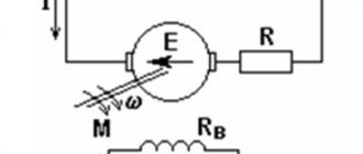
Let's consider this issue using the example of ADKR, as the most common type of electric motors in lifting, transport and processing equipment. The mains voltage is supplied to the stator winding, each of the three phases of which is geometrically displaced by 120°. After applying voltage, a magnetic field arises, which creates, by induction, an emf and a current in the rotor windings. The latter causes electromagnetic forces that cause the rotor to rotate. Another reason why all this happens, namely, EMF occurs, is the difference in the speed of the stator and rotor.
One of the key characteristics of any ADCR is the rotation speed, which can be calculated using the following relationship:
n=60f/p, rpm
where f is the frequency of the mains voltage, Hz; p – number of stator pole pairs.
All technical characteristics are indicated on a metal plate attached to the body. But if it is missing for some reason, then the number of revolutions must be determined manually using indirect indicators. Typically, three main methods are used:
- Calculation of revolutions taking into account the diametric pitch of the winding. To determine, a formula of the form is used:
where 2p – number of poles; Z1 – number of slots in the stator core; y – actually, the step of laying the winding.
Standard speed values:
- Calculation of the number of poles along the stator core. Mathematical formulas are used, which take into account the geometric parameters of the product:
2p = 0.35Z1b/h or 2p = 0.5Di/h,
where 2p – number of poles; Z1 – number of slots in the stator; b – tooth width, cm; h – backrest height, cm; Di is the internal diameter formed by the teeth of the core, cm.
After this, based on the data obtained and magnetic induction, it is necessary to determine the number of turns, which is checked against the motors’ passport data.
Ways to change engine speed
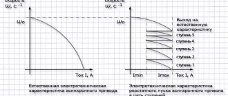
Adjusting the speed of any three-phase electric motor used in lifting and transport machinery and equipment allows you to achieve the required operating modes accurately and smoothly, which is not always possible, for example, due to mechanical gearboxes. In practice, seven main methods of rotation speed correction are used, which are divided into two key areas:
- Change in the speed of the magnetic field in the stator. Achieved by frequency regulation, switching the number of pole pairs or voltage correction. It should be added that these methods are applicable to electric motors with squirrel-cage rotor;
- Changing the amount of slip. This parameter can be adjusted by using the supply voltage, connecting additional resistance to the electrical circuit of the rotor, using a valve cascade or dual power supply. Used for models with wound rotor.
DIY making
If there is no opportunity or desire to purchase a factory-type regulator, then you can assemble it yourself. Although regulators of the "tda1085" type have proven themselves very well. To do this, you need to familiarize yourself with the theory in detail and start practicing. Triac circuits are very popular, in particular the speed controller of a 220V asynchronous motor (diagram 5). It's not difficult to make. It is assembled using a VT138 triac, which is well suited for these purposes.
Scheme 5 - Simple speed controller on a triac.
This regulator can also be used to adjust the speed of a 12-volt DC motor, as it is quite simple and universal. The speed is regulated by changing the parameters P1, which determines the phase of the incoming signal, which opens the transition of the triac.
The operating principle is simple. When the engine starts, it slows down, the inductance changes downward and contributes to an increase in U in the “R2—>P1—>C2” circuit. When C2 is discharged, the triac opens for some time.
Read also: How to properly connect a 380 to 220 electric motor
There is another scheme. It works a little differently: by providing a reverse type of energy flow, which is optimally beneficial. The circuit includes a fairly powerful thyristor.
Scheme 6 - Design of a thyristor regulator.
The circuit consists of a control signal generator, an amplifier, a thyristor and a circuit section that functions as a rotor rotation stabilizer.
The most universal circuit is a regulator based on a triac and dinistor (scheme 7). It is able to smoothly reduce the shaft rotation speed, reverse the motor (change the direction of rotation) and reduce the starting current.
The principle of operation of the circuit:
- C1 is charged until U breakdown of dinistor D1 through R2.
- When D1 breaks, it opens the junction of triac D2, which is responsible for controlling the load.
The load voltage is directly proportional to the frequency component when D2 opens, which depends on R2. The circuit is used in vacuum cleaners. It contains universal electronic control, as well as the ability to easily connect 380 V power. All parts should be placed on a printed circuit board made using laser-iron technology (LUT). You can find out more about this board manufacturing technology on the Internet.
Thus, when choosing an electric motor speed controller, you can buy a factory one or make it yourself. Making a homemade regulator is quite simple, since if you understand the principle of operation of the device, you can easily assemble it. In addition, you should follow safety rules when installing parts and when working with electricity.
Smooth engine operation, without jerks or power surges, is the key to its durability. To control these indicators, an electric motor speed controller is used for 220V, 12V and 24V; all of these frequencies can be made with your own hands or you can buy a ready-made unit.
Typical speed controller circuits
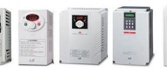
There is a wide selection of regulators and frequency converters for asynchronous motors on the market today. However, for the domestic needs of lifting or processing equipment, it is quite possible to calculate and assemble a homemade device on a microcircuit based on thyristors or powerful transistors.
Below is an example of a circuit of a fairly powerful regulator for an asynchronous motor. Due to this, you can achieve smooth control of its operating parameters, reduce energy consumption by up to 50%, and reduce maintenance costs.
This scheme is complex. For domestic needs, it can be significantly simplified by using a triac, for example, VT138-600, as a working element. In this case, the diagram will look like this:
The motor speed will be regulated by a potentiometer, which determines the phase of the input pulse that opens the triac.
As can be judged from the information presented above, not only its operating parameters, but also the efficiency of the powered lifting or processing equipment depend on the speed of an asynchronous motor. Today you can purchase a wide variety of regulators in the retail chain, but you can also make calculations and assemble an effective device with your own hands.
Due to their reliability and simplicity of design, asynchronous motors (IM) have become widespread. Most machine tools, industrial and household equipment use electric motors of this type. The rotation speed of the motor is changed mechanically (by additional load on the shaft, ballast, transmission mechanisms, gearboxes, etc.) or electrically. Electrical regulation is more complex, but also much more convenient and versatile.
For many units, electrical control is used. It provides precise and smooth control of engine starting and operation. Electrical control is achieved through:
- changes in current frequency;
- current strength;
- voltage level.
In this article we will look at popular methods of how the speed of an asynchronous motor can be adjusted at 220 and 380V.
220V electric motor speed controller
You can make it completely independently , but to do this you will need to study all the possible technical features of the device. By design, several types of main parts can be distinguished. Namely:
- The electric motor itself.
- Microcontroller control system for the conversion unit.
- Drive and mechanical parts that are associated with the operation of the system.
Just before starting the device, after applying a certain voltage to the windings, the process of rotating the engine begins with maximum power. It is this feature that will distinguish asynchronous devices from other types. On top of everything else, the load from the mechanisms that set the device in motion is added. Ultimately, at the initial stage of operation of the device, the power, as well as the current consumption, only increases to the maximum level.
At this time, the process of releasing the greatest amount of heat occurs. Overheating occurs in the windings, as well as in the wires. Using partial conversion will help prevent this from happening. If you install a soft start, then to the maximum speed mark (which can also be adjusted by equipment and may not be 1500 rpm, but only 1000), the engine will begin to accelerate not at the first moment of operation, but over the next 10 seconds (at the same time, every second the device will add 100-150 revolutions). At this time, the load on all mechanisms and wires begins to decrease several times.
How to make a regulator with your own hands
You can completely independently create an electric motor speed controller of about 12 V. To do this, you should use a switch of several positions at once , as well as a special wirewound resistor. With the help of the latter, the supply voltage level changes (and at the same time the rotation speed indicator). The same systems can be used to perform asynchronous movements, but they will be less effective.
Read also: Water pump increasing pressure
Many years ago, mechanical regulators were widely used - they were built on the basis of gear drives or their variators. But such devices were considered not very reliable. Electronic means showed themselves several times better, since they were not so large and allowed for finer adjustment of the drive.
In order to create an electric motor rotation controller, it is worth using several devices at once, which can either be bought at any hardware store or removed from old inventory devices. To complete the adjustment process, it is worth including a special variable resistor circuit . With its help, the process of changing the amplitude of the signal entering the resistor occurs.
Implementation of a management system
To significantly improve the performance of even the simplest equipment, it is worth connecting microcontroller control to the engine speed controller circuit. To do this, you should choose a processor that has a suitable number of inputs and outputs, respectively: to connect sensors, buttons, and special electronic keys.
To carry out experiments, it is worth using a special microcontroller AtMega 128 - this is the easiest to use and widely used controller. In free use you can find a large number of schemes using it. In order for the device to perform the correct operation, it is worth recording a certain algorithm of actions - responses to certain movements. For example, when the temperature reaches 60 degrees Celsius (the measurement will be noted on the graph of the device itself), the device should automatically turn off.
Operation adjustment
Now it’s worth talking about how you can adjust the speed in a brushed motor. Due to the fact that the overall speed of rotation of the motor can directly depend on the magnitude of the supplied voltage level, absolutely any control systems that can perform such a function are quite suitable for this.
It is worth listing several types of devices:
- Laboratory autotransformers (LATR).
- Factory control boards that are used in household devices (you can even take those that are used in vacuum cleaners and mixers).
- Buttons that are used in the design of power tools.
- Household types of regulators that are equipped with a special smooth action.
But at the same time, all such methods have a certain flaw. Together with the process of reducing speed, the overall power of the engine also decreases. Sometimes it can be stopped even by simply touching it with your hand. In some cases this may be quite normal, but for the most part it is considered a serious problem.
The most acceptable option would be to perform the function of adjusting the speed using a tachogenerator .
It is most often installed at the factory. When the rotation speed of the motors deviates through the triacs in the motor, the already adjusted power supply will be transmitted, accompanying the desired rotation speed. If control of the rotation of the motor itself is built into such a container, then power will not be lost.
What does this look like in design? Most of all, it is the rheostat control of the rotation process, which is created based on the use of a semiconductor.
In the first case, we will talk about variable resistance using a mechanical adjustment process. It will be connected in series to the commutator motor. The disadvantage in this case will be the additional release of some heat and an additional waste of the resource of the entire battery. During such an adjustment, a general loss of power occurs as the motor rotates. It is considered the most economical option. Not used for fairly powerful motors for the above reasons.
In the second case, during the use of semiconductors, the process of controlling the motor occurs by applying a certain number of pulses. The circuit is capable of changing the duration of such pulses, which, in turn, will change the overall speed of rotation of the motor without loss of power.
If you do not want to manufacture equipment yourself, but want to buy a device that is completely ready for use, then you should pay special attention to the main parameters and characteristics, such as power, type of device control system, voltage in the device, frequency, and operating voltage . It would be best to calculate the general characteristics of the entire mechanism in which it is worth using a general motor voltage regulator. It is worth remembering that you need to make a comparison with the parameters of the frequency converter.
Single-phase asynchronous motors are powered from a conventional 220 V alternating voltage network.
The most common design of such motors contains two (or more) windings - working and phase-shifting. The working one is fed directly, and the additional one is fed through a capacitor, which shifts the phase by 90 degrees, which creates a rotating magnetic field. Therefore, such motors are also called two-phase or capacitor motors.
It is necessary to regulate the rotation speed of such motors, for example, for:
- changes in air flow in the ventilation system
- pump performance control
- changes in the speed of moving parts, for example in machine tools, conveyors
In ventilation systems, this allows you to save energy, reduce the level of acoustic noise of the installation, and set the required performance.
Methods of regulation
We will not consider mechanical methods of changing the rotation speed, for example gearboxes, couplings, gear transmissions. We will also not touch upon the method of changing the number of poles of the windings.
Let's consider methods with changing electrical parameters:
- change in motor supply voltage
- change in supply voltage frequency
Changing the speed of an IM with a squirrel-cage rotor
There are several ways:
- Rotation control by changing the electromagnetic field of the stator: frequency regulation and changing the number of pole pairs.
- Changing the slip of the electric motor by decreasing or increasing the voltage (can be used for IMs with a wound rotor).
Frequency regulation
In this case, the adjustment is made using a frequency conversion device connected to the engine. For this purpose, powerful thyristor converters are used. The process of frequency regulation can be considered using the example of the EMF formula of a transformer:
This expression means that in order to maintain a constant magnetic flux, which means maintaining the overload capacity of the electric motor, the supply voltage level should be adjusted simultaneously with frequency conversion. If the expression calculated by the formula is saved:
then this means that the critical moment has not been changed. And the mechanical characteristics correspond to the figure below; if you do not understand what these characteristics mean, then in this case the adjustment occurs without loss of power and torque.
The advantages of this method are:
- smooth regulation;
- changing the rotor speed up and down;
- rigid mechanical characteristics;
- efficiency.
There is only one drawback - the need for a frequency converter, i.e. increase in the cost of the mechanism. By the way, on the modern market there are models with single-phase and three-phase input, the cost of which with a power of 2-3 kW is in the range of 100-150 dollars, which is not too expensive for full adjustment of the drive of machine tools in a private workshop.
Switching the number of pole pairs
This method is used for multi-speed motors with complex windings that allow you to change the number of pairs of its poles. The most widely used are two-speed, three-speed and four-speed IMs. The adjustment principle is easiest to consider on the basis of a two-speed IM. In such a machine, the winding of each phase consists of two half-windings. The rotation speed changes when connecting them in series or parallel.
In a four-speed electric motor, the winding is made in the form of two parts independent from each other. When the number of pole pairs of the first winding changes, the speed of the electric motor changes from 3000 to 1500 rpm. Using the second winding, rotation is adjusted at 1000 and 500 rpm.
When the number of pole pairs changes, the critical moment also changes. To keep it unchanged, it is necessary to simultaneously regulate the supply voltage while changing the number of pole pairs, for example, by switching the star-delta circuit and their variations.
Advantages of this method:
- rigid mechanical characteristics of the engine;
- high efficiency.
- step adjustment;
- large weight and overall dimensions;
- high cost of the electric motor.
Speed setting methods
To prevent negative influence during start-up, you need to reduce the speed of the electric motor 220 V or 380 V. There are several ways to achieve this goal:
- Changing the R value of the rotor circuit.
- Change in U in the stator winding.
- Change of frequency U.
- Switching poles.
When changing the R value of the rotor part using additional resistors, the rotation speed decreases, but as a result, the power decreases. Consequently, there is a significant loss of electricity. This type of regulation should be used for a wound rotor.
By changing the U values on the stator coil, mechanical or electrical control of the rotor speed is possible. In this case, the U regulator is used. Using this method allows it to be used only with a fan load (for example, a 220V fan speed regulator). For all other cases, three-phase automatic transformers are used, which allow smooth changes in U values, or thyristor regulators.
Based on the formula for the dependence of the rotation speed on the supply frequency U, it is possible to regulate the number of rotor revolutions. The frequency of the rotating magnetic field of the stator is calculated by the formula: Nst = 60 * f / p (f is the frequency of the supply network current, p is the number of pole pairs). This method provides the ability to smoothly control the rotation speed of the rotor part. To obtain a high efficiency, you need to change the frequency and U. This method is optimal for engines with a squirrel-cage rotor, since power losses are minimal. There are two methods for changing the number of pole pairs:
- In the stator (in the slots) you need to place 2 windings with different numbers p.
- The winding consists of two parts connected in parallel or in series.
The main disadvantage of this method is maintaining a stepwise change in the frequency of an electric motor with a squirrel-cage rotor.
Smooth start of asynchronous electric motors
In addition to unconditional advantages, ADs have significant disadvantages. This is a jerk at the start and high starting currents, 7 times higher than the rated ones. To soft start the electric motor, the following methods are used:
- switching of windings according to the star-delta circuit;
- turning on the electric motor through an autotransformer;
- use of specialized devices for soft starting.
Most frequency controllers have a soft motor start function. This not only reduces inrush currents, but also reduces the load on the actuators. Therefore, frequency regulation and soft starting are quite closely related.
How to make a device for changing the rotation speed of an electric motor with your own hands
Dimmers can be used to regulate low-power single-phase IM. However, this method is unreliable and has serious disadvantages: reduced efficiency, serious overheating of the device and the risk of engine damage.
For reliable and high-quality regulation of the speed of 220V electric motors, frequency regulation is best suited.
The diagram below allows you to assemble a frequency device for adjusting electric motors with a power of up to 500 W. The rotation speed is changed within the range from 1000 to 4000 rpm.
The device consists of a master oscillator with variable frequency, consisting of a multivibrator assembled on a K561LA7 microcircuit, a counter on a K561IE8 microcircuit, and a half-bridge regulator. Output transformer T1 decouples the upper and lower transistors of the half-bridge.
The damping circuit C4, R7 dampens voltage surges that are dangerous for power transistors VT3, VT4. The rectifier, a supply voltage doubler, includes a VD9 diode bridge, with a filter capacitor on which the half-bridge supply voltage is doubled.
Primary winding voltage: 2x12V, secondary winding 12V. The primary winding of the key control transformer consists of 120 turns of copper wire with a cross-section of 0.7 mm, with a tap from the middle. Secondary - two windings, each with 60 turns of a drive with a cross section of 0.7 mm.
The secondary windings must be insulated from each other as reliably as possible, since the potential difference between them reaches 640 V. The output windings are connected to the switch gates in antiphase.
So we looked at ways to adjust the speed of asynchronous motors. If you have any questions, ask them in the comments below the article!
- 0 commentsApplication February 14, 2019
The variable-speed induction drive is widespread and popular, so much so that it has virtually replaced synchronous electric motors and DC drives.
Options for adjusting the speed of an electric motor include several existing methods:
- Changing the voltage supply;
- Switching windings of asynchronous motors;
- Frequency control of electric motor speed by changing current values;
- Application of an electronic switch.
This was largely due to the advent of frequency converters that provide energy and dynamic performance. The use of a frequency speed controller is considered the most progressive and popular method included in the methods of adjusting the rotation speed of asynchronous motors.
The main purpose of a frequency speed controller for an asynchronous motor is based on providing power in such a way that the operating characteristics of the unit are radically different from the usual parameters obtained from the network. In this case, the network voltage and frequency must remain unchanged.
Frequency regulation
Just recently (10 years ago), there were a limited number of frequency controllers for motor speeds on the market, and they were quite expensive. The reason was that there were no cheap high-voltage power transistors and modules.
But developments in the field of solid-state electronics have made it possible to bring power IGBT modules to the market. As a result, there is a massive appearance on the market of inverter air conditioners, welding inverters, and frequency converters.
At the moment, frequency conversion is the main way to regulate the power, performance, speed of all devices and mechanisms driven by an electric motor.
However, frequency converters are designed to control three-phase electric motors.
Single-phase motors can be controlled by:
- specialized single-phase inverters
- three-phase inverters with the exception of the capacitor
Converters for single-phase motors
Currently, only one manufacturer announces serial production of a specialized inverter for capacitor motors - INVERTEK DRIVES.
Optidrive E2 model
For stable engine starting and operation, special algorithms are used.
In this case, frequency adjustment is possible upward, but in a limited frequency range, this is prevented by a capacitor installed in the phase-shifting winding circuit, since its resistance directly depends on the frequency of the current:
f – current frequency
C – capacitance of the capacitor
The output stage uses a bridge circuit with four output IGBT transistors:
Optidrive E2 allows you to control the motor without removing the capacitor from the circuit, that is, without changing the motor design - in some models this is quite difficult to do.
Advantages of a specialized frequency converter:
- intelligent motor control
- Stably stable engine operation
- Huge capabilities of modern inverters:
- the ability to control the operation of the engine to maintain certain characteristics (water pressure, air flow, speed under changing load)
- numerous protections (motor and device itself)
- sensor inputs (digital and analogue)
- various outputs
- communication interface (for control, monitoring)
- preset speeds
- PID controller
Disadvantages of using a single-phase inverter:
Using a state of emergency for three-phase motors
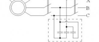
A standard frequency converter has a three-phase voltage at its output. When connecting a single-phase motor to it, remove the capacitor from it and connect it according to the diagram below:
The geometric arrangement of the windings relative to each other in the stator of an asynchronous motor is 90°:
The phase shift of the three-phase voltage is -120°, as a consequence of this - the magnetic field will not be circular, but pulsating and its level will be less than with a power supply with a shift of 90°.
In some capacitor motors, the additional winding is made of thinner wire and therefore has a higher resistance.
When operating without a capacitor, this will lead to:
- stronger heating of the winding (service life is reduced, short circuits and interturn short circuits are possible)
- different current in the windings
Many inverters have protection against current asymmetry in the windings; if it is impossible to disable this function in the device, operation using this circuit will be impossible
Advantages:
- lower cost compared to specialized inverters
- Huge selection of power and manufacturers
- wider frequency control range
- all the advantages of the inverter (inputs/outputs, intelligent operating algorithms, communication interfaces)
Disadvantages of the method:
- the need for preliminary selection of the inverter and motor for joint operation
- pulsating and reduced torque
- increased heating
- no warranty in case of failure, because Three-phase inverters are not designed to work with single-phase motors
Read also: Lm2480na description in Russian
Smooth engine operation, without jerks or power surges, is the key to its durability. To control these indicators, an electric motor speed controller is used for 220V, 12V and 24V; all of these frequencies can be made with your own hands or you can buy a ready-made unit.
Design and principle of operation, structure of the frequency regulator
The operating principle of a frequency regulator for an asynchronous motor is to supply the electric motor with an alternating voltage with amplitude and frequency parameters changing as needed. At the same time, the support voltage/frequency ratio remains clearly defined and unchanged. The generation of alternating voltage occurs thanks to a power electronic converter.
Rice. No. 1 Schematic diagram of the frequency converter.
The operating principle involves the use of pulse width modulation. The principle involves applying a pulse voltage to the motor windings with an amplitude equal to the voltage received from the rectifier. The pulses are width modulated and produce an alternating current voltage with varying amplitude. A good example is the phase-to-phase voltage and current curves in one motor winding when the windings are connected in a triangle.
Rice. No. 2 Graph of the voltage at the PWM output and the current in the motor winding when connecting a three-phase asynchronous motor in a triangle.
Voltage regulation
Speed control in this way is associated with a change in the so-called engine slip - the difference between the rotation speed of the magnetic field created by the stationary stator of the engine and its moving rotor:
n1 – magnetic field rotation speed
n2 – rotor rotation speed
In this case, sliding energy is necessarily released - which causes the motor windings to heat up more.
This method has a small regulation range, approximately 2:1, and can also only be carried out downwards - that is, by reducing the supply voltage.
When regulating speed in this way, it is necessary to install oversized motors.
But despite this, this method is used quite often for low-power motors with a fan load.
In practice, various regulator circuits are used for this.
Autotransformer voltage regulation
An autotransformer is an ordinary transformer, but with one winding and taps from some of the turns. In this case, there is no galvanic isolation from the network, but in this case it is not needed, so savings are achieved due to the absence of a secondary winding.
Read also: Iron content in steel
The diagram shows autotransformer T1 , switch SW1 , which receives taps with different voltages, and motor M1.
The adjustment is done in steps; usually no more than 5 steps of regulation are used.
Advantages of this scheme:
- undistorted output voltage waveform (pure sine wave)
- good overload capacity of the transformer
Flaws:
- large mass and dimensions of the transformer (depending on the power of the load motor)
- all the disadvantages inherent in voltage regulation
Thyristor engine speed controller
This circuit uses keys - two thyristors connected back-to-back (the voltage is alternating, so each thyristor passes its own half-wave of voltage) or a triac.
The control circuit regulates the moment of opening and closing of the thyristors relative to the phase transition through zero; accordingly, a piece is “cut off” at the beginning or, less often, at the end of the voltage wave.
This changes the rms voltage value.
This circuit is quite widely used to regulate active loads - incandescent lamps and all kinds of heating devices (so-called dimmers).
Another method of regulation is to skip half-cycles of the voltage wave, but at a network frequency of 50 Hz, this will be noticeable for the motor - noise and jerking during operation.
To control motors, regulators are modified due to the characteristics of the inductive load:
- install protective LRC circuits to protect the power switch (capacitors, resistors, chokes)
- add a capacitor at the output to adjust the voltage waveform
- limit the minimum voltage regulation power - for guaranteed engine start
- use thyristors with a current several times higher than the electric motor current
Advantages of thyristor regulators:
Flaws:
- can be used for low power engines
- During operation, noise, crackling, and jerking of the engine may occur.
- when using triacs, a constant voltage is applied to the motor
- all the disadvantages of voltage regulation
It is worth noting that in most modern mid- and high-level air conditioners, the fan speed is adjusted in this way.
Transistor voltage regulator
As the manufacturer himself calls it, an electronic autotransformer or PWM regulator.
The voltage change is carried out according to the PWM (pulse width modulation) principle, and transistors are used in the output stage - field-effect or bipolar with insulated gate (IGBT).
The output transistors are switched at a high frequency (about 50 kHz); if you change the width of the pulses and pauses between them, the resulting voltage at the load will also change. The shorter the pulse and the longer the pause between them, the lower the resulting voltage and power input.
For a motor, at a frequency of several tens of kHz, a change in the pulse width is equivalent to a change in voltage.
The output stage is the same as that of a frequency converter, only for one phase there is a diode rectifier and two transistors instead of six, and the control circuit changes the output voltage.
Advantages of an electronic autotransformer:
- Small dimensions and weight of the device
- Low cost
- Clean, undistorted current output waveform
- No hum at low speeds
- 0-10 Volt signal control
Weak sides:
- The distance from the device to the engine is no more than 5 meters (this disadvantage is eliminated when using a remote controller)
- All the disadvantages of voltage regulation
The main elements that make up the structure of the frequency converter
The frequency converter consists of the following components:
- A bridge rectifier for 1 or 3 phases, equipped with a capacitor at the output, is a source of constant voltage.
- A bridge inverter (IGBT) is supplied with a constant voltage using the pulse-width modulation method and is used to generate an alternating current voltage with variable amplitude and frequency.
- A control module that provides conductivity commands to the inverter. They depend on the signals supplied by the operator and information about the results of measurements of electrical quantities (mains voltage, motor load current).
Frequency controller structure
Currently, two main topologies of multilevel frequency converters have been developed in detail and are widely used. These are cascade and converters based on multi-level frequency voltage inverters.
Rice. No. 3 Block diagram of a high-voltage multilevel frequency converter, built on the basis of air- or water-cooled IGBT transistors.
The device includes a multi-winding transformer. Features of the circuit include the presence of power cells with a serial connection, due to which a total high voltage is obtained at the output of the device. Such a circuit serves to obtain an output voltage shape that is almost close to an ideal sine wave. The presence of cells that are shunted at the time of malfunction determines the high reliability of the circuit.
As a continuation of the previous circuit, we will consider a converter circuit based on a transformer multilevel voltage inverter with pulse width modulation using IGBT modules. The device is characterized by a fixed PWM frequency of 3 kHz. The structure of the device includes a protection system using a microprocessor.
Rice. 4 Block diagram of the converter.
The diagram shows that all blocks are functionally interconnected. The diagram shows how a frequency regulator works for an asynchronous motor, its structure and principle of operation.
The first block contains an input transformer; the block transmits electricity from a three-phase high-voltage power source. From the multi-level transformer, the reduced voltage is distributed into the inverter cabinet to the multi-level inverter.
The inverter cabinet includes a multi-level three-phase inverter consisting of converter cells. Each contains a six-pulse filter for rectifying the DC link and a bridge voltage inverter based on IGBT transistors. According to the circuit, the input alternating current is rectified, which, thanks to the inverter, is changed into alternating current with adjustable frequency and voltage.
The control protection cabinet contains a microprocessor unit with multifunctional capabilities and a power supply system from the converter TSN, a converter input device and primary sensors indicating the operating modes of the converter.
The microprocessor is used to generate inverter control signals depending on the designated operating algorithm. It is used to process information collected from voltage and current sensors. The microprocessor generates signals to control protections and emergency control buttons, and adjusts the control algorithm.
Fiber optic cable is used to transmit information and communication. For uninterrupted operation there is an independent built-in power supply. Parameter editing is performed using the remote control.
For reliable shutdown and safe performance of various types of work, the converter is equipped with a linear disconnector.
Rice. No. 5 Generalized diagram of the converter cell
Controlled alternating voltage sources form a voltage phase to perform their series connection. The output circuit of the supply network of an asynchronous motor occurs according to the “Star” winding connection diagram. The voltage in a three-phase inverter is distributed according to the circuit.
Rice. No. 6 Voltage distribution diagram in the inverter into three phases.
Composition of frequency converters
In addition to the rectifier, PWM modulator and inverter, the frequency converter includes:
A device for entering data and exchanging information with a PC and other frequency converters.
- Built-in non-volatile memory. This device records emergency shutdowns, settings changes, and other data.
- A control controller that ensures the implementation of control algorithms, processing data from sensors, and protective shutdown during abnormal operating conditions.
- EM filter. This device reduces the reactive high-frequency component, which reduces the quality of electricity and negatively affects the operation of the electric motor.
- Fan and radiator for forced cooling and heat removal of power transistors.
- Brake chopper and other elements.
In addition to the hardware, frequency converters contain software. Open logic controllers allow you to make changes to the standard software supplied by the manufacturer and program the inverter yourself.
Frequency converters for single-phase asynchronous electric motors
The use of small-sized frequency converters is used to control the rotation speed of single-phase motors used in the design of household devices and for the production of technological processes. For more information about regulating a single-phase asynchronous motor using a frequency converter, see here.
A frequency speed controller for an asynchronous motor will be extremely relevant in control circuits for devices such as air conditioners, refrigerators, electric fans, pumps, and all equipment using asynchronous electric motors.
System design
The commutator type motor consists mainly of a rotor, a stator, as well as brushes and a tachogenerator.
- The rotor is part of the rotation, the stator is an external type of magnet.
- Brushes, which are made of graphite, are the main part of the sliding contact, through which voltage is applied to the rotating armature.
- A tachogenerator is a device that monitors the rotation characteristics of a device. If there is a violation in the regularity of the rotation process, then it adjusts the voltage level entering the engine, thereby making it smoother and slower.
- Stator. Such a part may include not one magnet, but, for example, two pairs of poles. At the same time, instead of static magnets, there will be coils of electromagnets. Such a device is capable of performing work both from direct current and alternating current.
Read also: Units for measuring the tightening torque of threaded connections
Scheme of the speed controller of the commutator motor
Special frequency converters are used in the form of speed controllers for 220 V and 380 V electric motors . Such devices are considered high-tech , and they help to radically transform the current characteristics (signal shape, as well as frequency). They are equipped with powerful semiconductor transistors, as well as a pulse-width modulator. The entire process of operating the device occurs through the control of a special unit on a microcontroller. The change in speed in the rotation of the motor rotor occurs quite slowly.
It is for this reason that frequency converters are used in loaded devices. The slower the acceleration process occurs, the less load will be placed on the gearbox, as well as the conveyor. In all frequency generators you can find several degrees of protection: by load, current, voltage and other indicators.
Some models of frequency converters supply power from a single-phase voltage (it will reach 220 Volts) and create a three-phase voltage from it. This helps to connect an asynchronous motor at home without the use of particularly complex circuits and designs. In this case, the consumer will not lose power while working with such a device.
Why use such a device-regulator?
If we talk about regulator motors , then the required speed is:
- For significant energy savings. So, not every mechanism needs a lot of energy to perform the work of rotating the motor; in some cases, rotation can be reduced by 20-30 percent, which will help significantly reduce energy costs by several times.
- For the protection of all mechanisms, as well as electronic types of circuits. Using the converter frequency, you can exercise certain control over the overall temperature, pressure, as well as other indicators of the device. In the case when the engine operates as a specific pump, then a specific pressure sensor should be inserted into the container into which air or liquid is pumped. When the maximum mark is reached, the motor will simply automatically stop working.
- For the soft start process. There is no particular need to use additional electronic equipment - everything can be done by changing the settings of the frequency converter.
- To reduce device maintenance costs. With the help of such speed controllers in 220 V engines, the possibility of failure of devices, as well as certain types of mechanisms, can be significantly reduced.
The circuits used to create frequency converters in an electric motor are widely used in most household devices. Such a system can be found in wireless power supplies, welding machines, phone chargers, power supplies for personal computers and laptops, voltage stabilizers, lamp ignition units for backlighting modern monitors, as well as LCD TVs.
Features of using speed controllers for single-phase electric motors
The design of the frequency regulator includes several elements that ensure the efficiency of the device, these include:
- Built-in RS485 interface converter (optional);
- Built-in PLC controller;
- Built-in PID controller (generates a signal to control the device).
The advantageous features of using speed controllers include innovative vector control technologies. Significant energy-saving efficiency is a feature that is provided automatically. The speed controller can be controlled using a remote control, the minimum control distance is 5m.
Important: the design of the frequency converter provides the ability to automatically regulate the output voltage.
Mounting the regulator into the cavity of the angle grinder body
The electronic device, assembled separately from the angle grinder, is placed in a shell made of dielectric material, since all components are energized. A portable power socket with a cable is attached to the housing. The handle of the variable resistance resistor is placed outside. The regulator is connected to the mains, and the instrument is connected to a portable power outlet.
Popular models of speed controllers for single-phase motors
Among the variety of devices that perform the function of controlling an electric motor, there are two main types of speed controller models. These are electronic thyristor single-phase speed controllers that operate by smoothly changing the supply voltage. The second type of speed controller models is a transformer single-phase speed controller. Its work is to change the position of a three-stage cam switch, which changes the switching combination of the windings.
Frequency control for speed control of asynchronous electric motors is a technical standard nowadays. The use of a frequency regulator has replaced many control methods. Symmetrical and asymmetrical voltage control and the use of additional resistances, changing the number of pole pairs are a thing of the past.
How to make a homemade engine speed controller
You can make a simple triac motor speed controller, its diagram is presented below, and the price consists only of parts sold in any electrical store.
To work, we need a powerful triac of the BT138-600 type, it is recommended by a radio engineering magazine.
Photo - do-it-yourself speed controller diagram
In the described circuit, the speed will be adjusted using potentiometer P1. Parameter P1 determines the phase of the incoming pulse signal, which in turn opens the triac. This scheme can be used both in field farming and at home. You can use this regulator for sewing machines, fans, tabletop drilling machines.
The principle of operation is simple: at the moment when the motor slows down a little, its inductance drops, and this increases the voltage in R2-P1 and C3, which in turn leads to a longer opening of the triac.
A thyristor feedback regulator works a little differently. It provides energy back into the energy system, which is very economical and profitable. This electronic device involves the inclusion of a powerful thyristor in the electrical circuit. His diagram looks like this:
Here, to supply direct current and rectify, a control signal generator, an amplifier, a thyristor, and a speed stabilization circuit are required.
“>