For some reason, there are now few technical articles on Giktimes from independent, non-news and non-paid authors. I’ll try to correct this situation and tell you about how automated commercial electricity metering systems (ASCAE) work and what they are made of. Or more precisely, about how one of these systems was created at a single enterprise.
I advise you to treat the article as an engineer’s everyday sketches with elements of equipment reviews. In 2011, I was brought to work in the North of our homeland, in the forests and swamps, in one of the mining companies. I won’t tell you how and why I ended up there, the name of the employer’s company and what they actually mined there, but it was then that I, a novice IT engineer, had to get involved in the field of automation of electricity metering in production.
What did I see in front of me at the very beginning?
On the table stood a pot-bellied 17-inch Flatron and a Celeron 800 system unit with win xp + mssql and 1 gig of memory - aka a server, aka a client terminal for viewing and printing (for further faxing!) information on energy consumption.
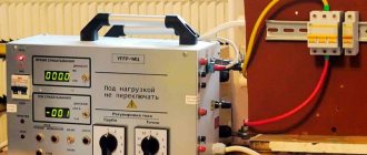
7 smart electricity meters (5 pcs. Mercury-230 and 2 pcs. Euro-Alpha A1600), connected via MoxaNPort - LAN to RS485 to a separate network card, as well as printout instructions for generating queries into the database to pull out the necessary information.
The task that I was assigned for the first 3 months of the probationary period:
- It must work stably in hardware terms in 24 x 7 mode.
- We need new reporting forms and automation of the transfer of reporting readings to the energy sales company.
- For the next time, if things go quickly: I would like to replace absolutely all analog meters available at the enterprise with “smart” ones, keep consumption statistics by department, see summary information on the load in various workshops with an accuracy of half an hour.
- Learn to plan the need for electricity for at least a year, in accordance with this, order a daily power limit from the energy supply organization, so as not to overpay in vain for inflated expectations and at the same time not be subject to penalties for consumption in excess of the declared power.
First steps.
At first I read, read a lot, crawled through specialized forums, delved into the concepts of ASKUE, RS-485, ModBus, and understood the tricky structure of the database formed by the electricity metering program.
At that time, I found a very useful blog that provided much of the initial knowledge.
There I also found a new version of the Mercury-230/234 electricity meter configuration program.
What is ASKUE and how does it work:
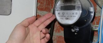
To account for electricity, electronic meters are used, each of them has its own microcontroller with a real-time clock, memory cells (48 cells per day for half-hour averaging of power consumption across 4 tariff zones for 90-180 days), measurement circuits and an external interface (CAN, RS-485, optical port, GSM modem, etc.).
The counter is differentiated by levels of access to data inside its memory.
The first level only allows you to read the readings and make adjustments to the built-in clock, but no more than 5 seconds during the day.
The second level makes it possible to change the date and time, the first level password, your password and, most importantly, configure all internal accounting parameters (tariff schedules, transformation ratio of the external current transformer, etc.).
As a result, at any time, upon request, we can receive from the device:
- Current readings (what is usually written down on paper at the end of the month);
- Readings with averages over half-hour time intervals from internal memory (90 - 180 days);
- Current power consumption;
- Readings for any day within a six-month interval;
- Other parameters: actual frequency of current in the electrical network, voltage level, current strength in the measured circuits, etc.
All devices can provide their accumulated data upon request from the server.
Counters (on the RS-485 bus) have addressing from 1 to 254, as a rule, the address is the last 2-3 digits of the device’s serial number, but it can be easily changed. Accordingly, up to 253 devices with different addresses can be connected to 1 physical RS-485 port.
There are also two service addresses 0 and 255, they cannot be occupied.
There can be as many RS-485 lines to which devices are connected.
The survey program is located on the data collection server. According to a given schedule, it opens the port to which the metering devices are connected and begins to send a packet with a request, then pauses and receives a packet with a response, and so on until all the necessary readings have been read or until there is a very long pause and the survey is interrupted. for loss of connection.
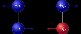
The readings are immediately laid out in the database, according to the linked control channels (for each metering device - 5 channels: active and reactive power consumption, active and reactive power generation, reference readings at the beginning of the month). There are two directions for accounting for each component of power - due to the fact that the meters can count in both directions, that is, in theory - they can be used to sell excess electricity, but in my practice this has not been used. Although it was possible to record emissions of electricity generation when braking AC power motors.
As a result, per day of work we get this picture of active power consumption (this is one of the main metering devices, it calculates how much electricity is consumed by the entire organization from one of the high-voltage lines with a voltage of 110 kilovolts). In this and all subsequent screenshots, the vertical axis is in kilowatts.
The meter polling protocol resembles modbus, but is not it in its pure form.
At some point in time, I even had a desire to write my own version of the survey program in C#, since there is nothing complicated in implementing the protocol, but at first I didn’t have enough working time, and then the server software manufacturer released an update that was more or less it worked tolerably.
I am not specifying the software manufacturer so that there is no advertising, I will only say that in addition to commercial products, there are free versions of programs for polling meters.
For those who want to dig deeper and write something on their own, a description of the protocol can be downloaded here.
In order to physically connect metering devices to the server, you need to use interface converters. Essentially, we need the RS-485 bus to be visible in the system as a virtual COM port. You can use various versions of USB - RS-485 adapters; they are usually made on the basis of the FT232 microcircuit or analogues.
But this option is suitable for tests when there are very few metering devices or all of them are located at a fairly close distance from the server.
In my situation, the meters were scattered throughout the organization, and it was difficult to reach some of them with at least some kind of wired communication line.
As a result, for faster network deployment, it was decided to use MoxaNPort 5130 and MoxaNPort 5132. They made it possible to connect RS-485 to the organization’s local network.
After the update, the ASKUE server itself was included in the company’s general local network. WinXP was replaced with Win2003 server, sql was migrated along with the old database to sql 2008 (a separate article can be written about migration problems, so I will not touch on this point now).
The machine got a new dual-core hardware with 4 gigs of RAM.
Brakes and memory overuse are a thing of the past, and it is now possible to start polling on ten or more ports at once. And most importantly, the server was now accessible from anywhere on the local network, that is, it became possible to install the client software on any PC of the employee responsible for reporting on electricity consumption.
As a result, the concept of expanding the data collection network began to look like this:
1) We divide all metering points into zones to which we can reach wired communication lines; 2) We find a point where you can connect to the local network and at the same time the point that is closest to the bulk of the metering devices in this zone. It is desirable that when laying cables there should be as few overhead spans between buildings as possible. Next, we extend the communication line through all the devices to the moxa, avoiding long branches away from the main line; 3) On the server we register moxa as a virtual com port and work in the data collection software through it.
When implementing point 2, as it turned out, at short distances and in industrial premises (warehouses, garages, repair shops) the ordinary field, which is P-274, performs very well as a twisted pair for RS-485.
The maximum length of the line laid by P-274 was 500m and it is still in operation (already 5 years). At the same time, mice and rats are not afraid of the vole (more precisely, they are not interested in it, because it is very hard and not tasty), thanks to its strong insulation and steel conductors - it has good self-supporting properties, that is, it can throw spans of 10-15 meters.
And the main advantage: the price is pennies compared to a special cable.
Yes, the characteristic impedance is not the same, yes - the signal shape changes greatly towards the end of the line, but at short distances everything works fine.
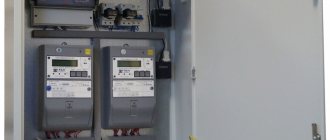
Why were 2-port MoxaNPort 5132 used in some places? It’s just that at some facilities it turned out that the lines to the devices went in different directions, and in order not to interfere with turning the lines in the opposite direction, they were connected to different ports. It also increased the reliability of the system as a whole. If for some reason there was a line short circuit on one of the ports, the second port continued to work.
Tale No. 1 About the wire...
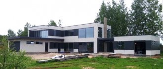
One of the metering points to which it was necessary to lay a wired communication line was located in the garage for BelAz, for those who do not know - this is such a hefty hangar, the height of a 6-7 storey building, there are no service ceilings inside from floor to roof and other supporting platforms.
But in the geometric center of the building there is a 6000/380V power electrical installation with operating currents up to 600A, and in the immediate vicinity of it (but not strictly above it, this is important), right under the ceiling, a crane rides on rails, which can easily move an entire BelAZ. from one point of the hangar to another.
The correct access to the electrical installation is a high-voltage cable duct, but laying low-current RS-485 lines in it is strictly prohibited. Therefore, the “wrong” but safe path was chosen: From the distribution box from the roof of the building, through the hole in the service window - vertically down to the electrical installation. Moreover, the service telephone cable had already been laid in the same way.
The laying plan has been agreed upon, the team has been assembled, we begin. Alexey, one of the installers, had wildly celebrated some holiday the night before and was unable to carry out the work at height. He was left below to control the descent of the cable to the designated point.
What followed was a long climb to the very top of the roof along fire escapes (don’t forget about the tool and cable bundle). Then they marked and drilled a hole in the proposed location, and shined a flashlight into it so that Alexey, who was seven floors below, could assess the correctness of the measurements and the correspondence of the location of the hole to the intended cable entry point.
We began lowering the cable, simultaneously discussing the process with the observer left below - by phone:
Me: Lekha, do you see the cable? Alexey: Not yet Me: Did you see the hole when the light was on? Alexey: Yes, I saw it, probably the cable was blocked and it is not visible against the background of the roof. Me: Well, make sure you don’t touch anything, when you see it, let me know Alexey: I see! I descended from the ceiling about 5-7 meters, let's do more Me: Make sure you don't hit the lamps or interfere with the crane Alexey: Everything is fine, let's do more... ... Alexey: All the guys, that's enough, fasten your end and get down, I'll start cutting the cable Me: Is everything okay? Is it long enough? Didn't you wrap the lamps? Will the crane pass? Alexey: Yes, that's all Oh no, let's go down already.
10-15 minutes passed, we went down, approached Alexey, who was busy laying electrical cabinets and securing the cable, and observed the picture: The cable runs vertically down from the roof and passes neatly between the rails of the crane. That is, exactly where the crane should pass.
I am Alexey! Raise your head! Nothing bothers you? Alexey: The cable is hanging, it didn’t touch the lamps, it doesn’t touch the rail, it’s right between... Alexey: Damn... That's the wrong crane... How's that...?
Naturally, the installation work had to be redone.
In general, there were many similar moments, but this one was especially memorable.
Thus, the network grew quite quickly and produced its first results.
I remember one morning. It was -30 outside, and the temperature stayed that way all night. At the entrance to work, I was greeted by a smiling girl (yes, yes, at night the electricians on duty were girls and women), after a while she said the phrase:
“It’s so good that this thing worked, now you don’t have to run outside every hour and take reference readings.” At this moment, I won’t lie, it felt damn good.
I will try to explain the reason for her joy. Previously, in an electrical installation on the street in a container, there were ordinary analog meters. On a certain night of the month (like every first Wednesday), readings had to be taken from them exactly at 00:00, 01:00, 02:00 and 03:00 a.m., in order to then be sent for verification to the power supply organization. And now, after installing “smart devices”, this could be done in the morning, with one click, from a warm office, since the necessary data was read automatically around the clock.
Installation process of the ASKUE system
Installation of an ASKUE system requires the installation of a set of equipment, and the development of a project precedes the actual installation. The fact is that the installation of an ASKUE system must be carried out taking into account all the features of the facility where the installation is being carried out: the types of energy resources that are used, as well as the scale of production, are also important. Based on them, the necessary equipment and its quantity are calculated and selected, and depending on the current situation at the site, the devices may vary.
Installation of the ASKUE system is carried out in several stages:
- First of all, cable lines are laid and installed.
- Then the ASKUE system is installed directly: adapters, modems, metering devices, communication lines.
- Next comes commissioning work.
- After this, the system is ready for commissioning.
Tale No. 2 About the first salary
The first month of work was coming to an end, it was damp northern September, and I had already climbed all possible electrical installations in a creative search for a faster and cheaper way to connect to the network.
The first cables have been laid. The work has reached a stable speed, every 2-3 days a new metering point is connected to the system (and this is all despite the fact that each connection case is unique, somewhere it is necessary to work out, coordinate and lay a 100m communication line along cable shelves at a height 4 floors, where you need to gain access to the premises of other services, going through 7 circles of hell of bureaucracy and other paperwork). By the end of the first month, what was already there before me worked stably, new reporting forms pulled out the necessary information from the database, which could then be exported to Excel and transferred wherever required. And so, I received my first salary in this place, as I remember now: 9,600 rubles... For a month... In 2011...!
First thought: I earned 4 times more as a freelancer while studying, what the hell... Second thought: I’ll quit today...
Then, of course, they explained to me that everyone’s salary was the same in the first month: due to the lack of bonuses, allowances and other pleasant perks. But then I wanted to quit, without explanation.
But, let's return to the network.
Slowly, miscalculations in the design and lack of experience in this area began to emerge. First, in winter, for unknown reasons, several interface ports on the meters went down, then with the arrival of spring and the beginning of the period of thunderstorms, a number of more meters went silent forever, leaving server requests unanswered.
Here, it’s probably worth saying thank you to the manufacturing company - they made replacements under warranty, despite the cause of the malfunction, which is very nice when you need to repair a dozen devices at once.
As a result, after another thunderstorm and subsequent repairs, it became clear that long lines need protection from static electricity.
Having studied everything that was on sale at that time, the choice fell on the DTR 2/6/1500 SPD modules. Again, I am writing the name not for the sake of advertising, but with the aim of sharing a time-tested solution and possibly saving someone time.
First, the protection was installed on long street RS-485 lines, and then, after not a single new meter burnout occurred in these directions over the course of a year, it was added to all other wire lines. The protection was installed on both sides of a long line in close proximity to the meter on one side and in front of the moxa port on the other.
Do not forget that the protection device requires mandatory grounding.
In my memory, the protection modules burned out several times during lightning strikes near the communication line, but the moxa port and counter ports remained intact. That is, even through self-sacrifice, she did her job. In winter, due to induced static in long lines, burnouts of protection and equipment no longer occurred.
It’s a funny fact, but when you see hourly consumption, you involuntarily begin to think about saving electricity.
Example from life:
One working day, the replacement of the industrial highway lighting line began. Old lamps based on DRL-250 (250W with uniform burning and up to 500W at the time of start-up) were replaced with modern 40-90W LED ones.
This fact immediately affected the electricity consumption of this line (the meter only takes into account the lighting line). According to our calculations, the new lamps, despite their fairly high cost, paid for themselves in 3 years of operation using electricity alone.
Before replacement
After replacement
Of course, 40W lamps were inferior in brightness to old lamps, but 90W lamps were quite comparable to them. Since the same number of both were purchased, the management simply ordered them to be placed one after the other. So the overall lighting level remained the same. In addition, in winter it has become noticeably lighter, since the light from LED lamps is reflected from the snow-covered surface.
When all the electricity distribution and metering nodes located in the immediate vicinity of the local network were mastered, it was decided to move to geographically remote facilities. The closest one was 2.2 km away; before it there was a single communication line based on the TPPep 20x2x0.5 telephone cable, which had a free pair. We tried to pass RS-485 through this pair, but it worked extremely unstable. At speed 9600, packet loss reached 50%.
But besides this node there were objects in even less accessible places.
We began to consider the option of communication using data transmission over power lines. As it turned out, there are no inexpensive solutions in Russia that would allow transmitting telemetry data over power lines with a voltage of 6 kV or more.
On a single-phase network 220V - that’s enough, on a three-phase network 380V - you can find it, but for 6-10 kilovolts, so that it can stretch 10-15 km, and in conditions of interference in the line from switching emissions of mining equipment - sorry - there is no such thing.
Then we looked towards the cellular connection.
Electricity meters with built-in GSM modems were purchased, but after they were delivered, one did not work right away. There was something dangling inside; it sounded like coins in a piggy bank. Well, we installed the two that remained intact.
And then we immediately noticed 3 problems:
1) Technical support for our corporate OPSoS account did not know what data transfer via CSD was. Accordingly, they also did not know how to enable it on the SIM cards we selected. Redirection to qualified technical support engineers ended with a melody and the words of a female robot: “Your call is very important for us...”. It’s good that the guys from “Tale No. 3” helped later, but a lot of time was spent on this stage. 2) If you set up a poll via the CSD channel (default settings) and receive data every half hour, then at the end of the month you can receive a bill for communication services of 34 thousand rubles. Because a minute of CSD costs 1.5 rubles. 3) The modems built into the meters freeze with enviable regularity; they can only be rebooted by disconnecting the entire meter from electricity. No, of course, we disconnected the 6 kV line several times along with all consumers, just to reboot the meter. A team went to the installation site several times to reboot the meter without disconnecting the high-voltage line, but the problem remained.
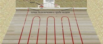
Installation and commissioning of the system
Each ASKUE subscriber is connected individually. The person supervising this process must have an Excel file with a consumer database. This database contains the name and contact information of the subscriber, as well as the model and serial number of the meter. If the meter has a digital telemetry port, you need to write down the address of the network device. If the output is a discrete signal, a sensor of the appropriate type is installed, for which the network address is set manually and also entered into the database.
The meter or the sensor installed on it is connected to the system hub directly through a wired connection. This is what is good about the UART protocol: the cable can be laid from subscriber to subscriber over a distance of up to a kilometer, it is only important to proportionally reduce the transmission speed. Communication methods in ASKUE can be combined, for example, by connecting remote groups of subscribers via a radio point or via GSM. In the end, everything turns out only to be additional costs for equipment for communication and signal conversion, as well as the choice of appropriate program settings. The subscriber connection method must be entered into the database in the notes field.
Before installing the meter, it is parameterized: the settings are reset, the real-time clock is synchronized, the correct type of output signal and communication settings are generated - a step-by-step procedure according to the user manual. When using interface converters, they must first set the address in accordance with the network topology, as well as study the operating instructions and configure communication parameters using the current protocol. Since the system core is still connected by a serial interface, you can connect to it at any point. Therefore, all equipment installed on the consumer side can be pre-installed on a stand for adjustment and testing in convenient conditions, and then transferred to the installation site practically assembled. There is no need to change the subscriber connection settings in the administration complex database.