Calculation of the characteristics of an asynchronous motor
Guidelines for performing practical work in the course
“Electromechanical Systems” for students of specialty 210100 of all forms of study
Balakovo Institute of Technology,
technology and management
An electric drive with a three-phase asynchronous motor (IM) is the most widespread type of drive in industry, utilities and agriculture. This situation is determined by the ease of manufacture and operation of IM, lower weight, overall dimensions and cost compared to DPT, as well as high operational reliability.
The main general industrial series 4A includes motors with power from 0.06 to 400 kW and heights of rotation axes from 50 to 355 mm, which are produced in a wide variety of modifications and designs: with increased starting torque and slip; with wound rotor; built-in; low noise; with built-in temperature protection; with electromagnetic brake; with plain bearings; chemical resistant. ADs also differ in climatic design and location category. To complete high-power electric motors, the AN-2 series (with a power of up to 2000 kW), AB (with a power of up to 8000 kW), DAZO (with a power of up to 1250 kW) and a number of others are produced.
Purpose of the work: calculation of an asynchronous three-phase motor, determination of motor parameters and construction of mechanical characteristics.
Specifics and features of three-phase networks
Three-phase electrical networks most efficiently transmit current through intermediate links, right up to the consumer. During the delivery process, energy losses are minimal.
The presence of a three-phase network in an apartment or private house is very easy to determine. To do this, you just need to look into the panel and count the number of wires. If there are 2 or 3 conductors, then the network is single-phase. There are two wires in it: phase and zero. If there is a ground, there may be a third wire. In three-phase networks there are two more wires due to the two additional phases. In the absence of grounding, there are only four of them, and in the presence of a grounding loop, there are five.
The same problem can be solved using an input circuit breaker. A certain number of wires are also supplied to it, connected to the appropriate terminals.
During the operation of a three-phase network, there is a high probability of uneven load distribution across individual phases. If only powerful equipment is connected to one of them, and ordinary household appliances are connected to the others, a situation called phase imbalance may arise. As a result of current and voltage asymmetry, individual consumers may fail. To avoid negative consequences, the load must be evenly planned at the design stage and the power of the three-phase network must be calculated.
A three-phase network, compared to a single-phase network, is distinguished by a large number of cables and wires, automatic devices and other devices. Specific three-phase equipment is connected to it. The total power will be exactly three times higher. The power value is calculated from current and voltage using formulas.
Basic theoretical information
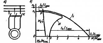
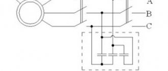
A three-phase IM has a stator winding connected to a three-phase AC network with voltage U1 and frequency f1, and a rotor winding, which can be made in two versions. The first option involves making a conventional three-phase winding of conductors with leads to three slip rings. This design corresponds to an IM with a wound rotor (Fig. 1, a ).
it allows you to include various electrical elements in the rotor circuit, for example, resistors for regulating the speed, current and torque of the electric motor, and create special circuits for switching on the IM.
Figure 1 - IM with wound rotor
The second option is to perform the winding by pouring aluminum into the grooves of the rotor, resulting in a structure known as a “squirrel cage”. The circuit of an IM with such a winding, which has no leads and is called short-circuited, is shown in Fig. 1, b.
To obtain expressions for the electromechanical and mechanical characteristics of the motor, its equivalent circuit is used, in which the stator and rotor circuits are represented by their active and inductive resistances. The peculiarity of the IM equivalent circuit is that in it the current, EMF and parameters of the rotor circuit are recalculated (reduced) to the stator circuit, which allows these two circuits to be depicted in the diagram as electrically connected, although in reality the connection between them is carried out through an electromagnetic field. The reduction is carried out using the transformation coefficient of the blood pressure according to the emf:
where E 1
and
E 2k –
phase EMF of the stator and rotor with a stationary rotor;
U
ph.nom – phase rated voltage of the network. The calculation formulas for the reduction are as follows:
-where the prime indicates the given values.
As can be seen from Fig. 2, the stator EMF is equal to the reduced rotor EMF, and the magnetizing current I t ,
determining the magnetic flux of the IM, flows under the influence of U
f
through
and R
m
, and
is
.
Mechanical characteristics of blood pressure.
Power losses in the rotor circuit, which are often called sliding losses, expressed through the mechanical coordinates of the motor, represent the difference between electromagnetic and useful mechanical power, i.e.
(1)
Power losses in the rotor, expressed through electrical quantities, are defined as
Three-phase squirrel-cage asynchronous motor
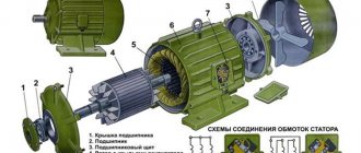
Construction of an asynchronous electric motor
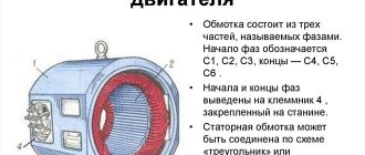
Stator
consists of a body and a core with a winding. The stator core is assembled from thin sheet technical steel, usually 0.5 mm thick, coated with insulating varnish. The laminated core design contributes to a significant reduction in eddy currents arising during the process of magnetization reversal of the core by a rotating magnetic field. The stator windings are located in the slots of the core.
Rotor
consists of a core with a short-circuited winding and a shaft. The rotor core also has a laminated design. In this case, the rotor sheets are not varnished, since the current has a low frequency and the oxide film is sufficient to limit eddy currents.
Principle of operation. Rotating magnetic field
The operating principle of a three-phase asynchronous electric motor is based on the ability of a three-phase winding to create a rotating magnetic field when connected to a three-phase current network.
The rotation frequency of this field, or the synchronous rotation frequency, is directly proportional to the frequency of the alternating current f1 and inversely proportional to the number of pole pairs p of the three-phase winding.
,
Rotating magnetic field concept
To understand the rotating magnetic field phenomenon better, consider a simplified three-phase winding with three turns. Current flowing through a conductor creates a magnetic field around it. The figure below shows the field created by three-phase alternating current at a specific point in time
The components of alternating current will change over time, causing the magnetic field they create to change. In this case, the resulting magnetic field of the three-phase winding will take different orientations, while maintaining the same amplitude.
The effect of a rotating magnetic field on a closed loop
Now let's place a closed conductor inside a rotating magnetic field. According to the law of electromagnetic induction, a changing magnetic field will give rise to an electromotive force (EMF) in the conductor. In turn, the EMF will cause a current in the conductor. Thus, in a magnetic field there will be a closed conductor with a current, on which, according to Ampere’s law, a force will act, as a result of which the circuit will begin to rotate.
The influence of a rotating magnetic field on a closed conductor carrying current
Squirrel-cage rotor of an asynchronous motor
An asynchronous electric motor also operates on this principle. Instead of a current-carrying frame, inside the asynchronous motor there is a squirrel-cage rotor whose design resembles a squirrel wheel. A squirrel-cage rotor consists of rods short-circuited at the ends with rings.
Squirrel cage rotor most widely used in induction motors (shown without shaft or core)
Three-phase alternating current, passing through the stator windings, creates a rotating magnetic field. Thus, also as described earlier, a current will be induced in the rotor bars, causing the rotor to start rotating. In the figure below you can notice the difference between the induced currents in the rods. This occurs due to the fact that the magnitude of the change in the magnetic field differs in different pairs of rods, due to their different locations relative to the field. The change in current in the rods will change with time.
You may also notice that the rotor arms are tilted relative to the axis of rotation. This is done in order to reduce the higher harmonics of the EMF and get rid of torque ripple. If the rods were directed along the axis of rotation, then a pulsating magnetic field would arise in them due to the fact that the magnetic resistance of the winding is much higher than the magnetic resistance of the stator teeth.
Slip of an asynchronous motor. Rotor speed
A distinctive feature of an asynchronous motor is that the rotor speed n2 is less than the synchronous speed of the stator magnetic field n1.
Website for electricians
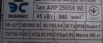
Example. A 3-phase IM with a short-circuit rotor type AIR180M4 receives power from a 3-phase network with a linear voltage U1 = 380 V, frequency 50 Hz. Data of the rated mode of the engine: shaft power P2NOM = 30 kW; synchronous speed n1 = 1500 rpm; nominal slip sNOM = 2.0%; power factor cosϕNOM = 0.87; efficiency ηNOM = 92%; critical multiplicity kM = 2.7; starting torque kP = 1.7; multiplicity of starting current iП = 7; The connection of the stator windings is star.
Find: number of pairs of pluses; rated rotor speed; rated phase voltage; rated phase current of the stator winding; rated torque on the shaft; critical slip and engine torque; starting torque at rated voltage and a decrease in its value by 20%; starting current; capacitor capacity to increase the power factor to 1 and draw an electrical circuit of the motor with the inclusion of capacitors.
Solution:
An asynchronous electric motor with a squirrel-cage rotor is
We determine the number of pole pairs of the stator winding:
We calculate the nominal rotor speed: rpm.
We find the rated phase voltage: When connected to a “star” V.
We calculate the rated phase current of the stator winding: A.
We determine the nominal torque on the shaft: N⋅m.
We calculate the critical slip:
We find the critical moment: N⋅m.
We calculate the starting torque at rated voltage: N⋅m, at reduced voltage: N⋅m,
Determine the starting current: A.
We calculate the capacitance of the capacitors to increase the power factor to 1.
The formula for the capacitance of compensating capacitors connected in a star configuration is: F.
The formula for the capacitance of compensating capacitors connected in a delta circuit is: F,
where f is the frequency of the power supply network, Hz; QK — reactive power, var; PHOM—active power, W; U1—line voltage, V; ϕ1 and ϕ2 are respectively the phase shift angles between voltage and current before and after switching on the capacitor bank, degrees. hail; hail
Then, the capacitance of the capacitors, when connected “in a star”, will be equal to: F or 1124.89 µF.
When connected in a “triangle”, the capacitance of the capacitors will be three times less than when connected in a “star” and is equal to: F or 374.96 µF.
In the “triangle” connection of capacitors, the battery capacity will be three times less, but the voltage on the capacitors is higher when compared with the “star” connection of capacitors.
We draw a circuit for connecting capacitors to increase the power factor of an electrical network with an asynchronous motor.
Read more about reactive power here.
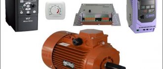
Asynchronous motor control
Direct connection to mains power
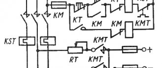
The use of magnetic starters allows you to control asynchronous electric motors by directly connecting the motor to an alternating current network.
Using magnetic starters you can implement the following circuit:
The use of a thermal relay makes it possible to protect the electric motor from current values much higher than the rated value.
Non-reversible circuit
Reversible circuit
The disadvantage of direct commutation of the windings of an asynchronous electric motor with the network is the presence of large starting currents when starting the electric motor.
Smooth start of an asynchronous electric motor
In tasks where it is not necessary to adjust the speed of the electric motor during operation, a soft starter is used to reduce starting currents.
The soft starter protects the asynchronous electric motor from damage caused by a sharp increase in energy consumption during starting by limiting the starting currents. The soft start device allows for smooth acceleration and braking of an asynchronous electric motor.
Three-phase asynchronous motor with wound rotor
Before the widespread use of frequency converters, medium and high power asynchronous motors were made with a wound rotor. Three-phase slip-rotor induction motors (ASMs) are typically used in applications with severe starting conditions, such as AC crane motors, or to drive devices requiring continuously variable speed control.
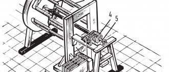
ADFR design
Slip rotor
Structurally, the phase rotor is a three-phase winding (similar to the stator winding) placed in the slots of the phase rotor core. The ends of the phases of such a rotor winding are usually connected in a “star”, and the beginnings are connected to slip rings isolated from each other and from the shaft. A three-phase starting or control rheostat is usually connected to the slip rings through brushes. Asynchronous motors with a wound rotor have a more complex design than motors with a squirrel-cage rotor, but have better starting and control properties.
Slip rotor
Types of Electric Motors
DC motors
The main advantage of these engines, which determined their widespread use at the stage of development of electric drives, is the ease of smooth speed control over a wide range. Therefore, with the development of the semiconductor industry and the advent of relatively inexpensive frequency converters, the percentage of their use is constantly decreasing. Where possible, DC motors are being replaced by drives based on squirrel-cage asynchronous motors.
The main disadvantages of a DC motor (low reliability, complexity of maintenance and operation) are due to the presence of a collector unit. In addition, to power the motor, a DC source or a thyristor AC-to-DC converter is required. Despite all their shortcomings, DC motors have a high starting torque and a large overload capacity. What determined their use in the metallurgical industry, machine tool industry and electric transport.
Synchronous motors
The main advantage of these motors is that they can operate with a power factor of cosφ=1, and in overexcitation mode they can even supply reactive power to the network, which has a beneficial effect on the characteristics of the network: its power factor increases, losses and voltage drop are reduced. In addition, synchronous motors are resistant to network fluctuations. The maximum torque of a synchronous motor is proportional to the voltage, while the torque of an asynchronous motor is proportional to the square of the voltage. Consequently, when the voltage decreases, the synchronous motor retains a greater overload capacity, and the ability to force excitation increases the reliability of their operation during emergency voltage drops. The larger air gap compared to an asynchronous motor and the use of permanent magnets make the efficiency of synchronous motors higher. Their feature is also the constancy of the rotation speed when the load torque on the shaft changes.