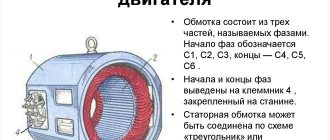
An energy crisis is often accompanied by power outages, especially if the problem affects rural areas. Having a backup generator is not always possible for a number of reasons, so you can use a “free” source of wind energy. To do this, you need a wind generator, which is easiest to build from a conventional asynchronous motor.
The principle of operation of such a generator is very simple: wind energy will be transferred to the rotor, which will begin to rotate in the same direction as the magnetic field created. Since the rotor slip becomes negative, a braking torque occurs on the rotor shaft, and the generated electrical energy will be transferred to the consumer. Thus, the magnetization of the rotor becomes the cause of excitation of the emf in the output circuit of the machine.
Advantages of an asynchronous generator:
- Structurally, such a generator is simpler than a synchronous one, and, moreover, is not critical to external adverse influences: for example, to the ingress of dust and dirt (which is quite likely in strong wind conditions).
- The output voltage has a lower degree of nonlinear distortion, and therefore various loads can be connected to such a generator - from a welding converter to a computer.
- The rotation unevenness coefficient for asynchronous generators does not fall below 0.98, which prevents overheating during long-term operation.
- Due to the absence of rotating windings, the durability of an asynchronous generator is expected to be quite high.
Thus, making a wind generator from an asynchronous motor is not only possible in principle, but also practically feasible.
Schematic diagram
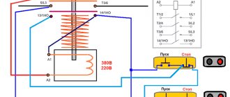
The connection diagram for an asynchronous motor with a squirrel-cage rotor is shown in Figure No. 1. When the motor rotor rotates, a residual magnetic field acts on one of the stator windings. In this case, a small electric current arises, which charges one of the capacitors C1-C3. Due to the fact that the phase of the voltage on the capacitor lags behind, a magnetic field of greater magnitude appears on the rotor, which acts on the next winding. Accordingly, the next capacitor will be charged at a higher voltage. This process continues until the generator rotor enters saturation (1...1.15 s). After this, you can turn on the B2 machine and use the energy generated by the generator.
Rice. 1. Connection diagram for an asynchronous motor to operate as an electricity generator.
Moreover, for normal operation of the engine in generator mode, the load power should be no more than 80% of the engine used as a generator. The remaining 20% is used to maintain the voltage on the capacitors, i.e. maintaining the generator in working condition.
If this condition is exceeded, the voltage on the capacitors will disappear, which means the magnetic field on the armature will disappear, which will lead to the disappearance of voltage at the terminals of the B2 machine. Moreover, this happens almost instantly.
This has its drawbacks and its advantages. The disadvantage is that reapplying voltage is possible only when the cause of the overload is eliminated and the B2 circuit breaker is turned off. The generator will sleepily enter operating mode (in 1...1.5 s).
After this, you can turn on B2 and use the energy. An advantage is the fact that it is almost impossible to burn the generator, since the voltage at its terminals disappears instantly within 0.1...0.5 s.
The output voltage has a sinusoidal shape and is completely suitable for further use. The generator output frequency is 46…60 Hz, which in most cases is sufficient for home use. Due to the instability of the voltage at the voltage output, it is necessary to install a stabilizer (a description of the circuit and operation is described in an additional article).
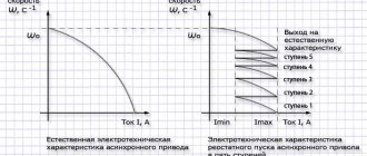
Rice. 3. Driving force.
The capacity of additional capacitors is indicated in Table No. 1, per kilowatt of the specified motor power, and for operation with a load - additional capacitance for each kilowatt of load.
Table No. 1 Capacity of capacitors included in the phases, in microfarads per 1 kW of power.
| Voltage between phases | Main capacitance (uF) | ||
| At idle | With active load | Under reactive load | |
| 127 V | 40…50 | 10…20 | 50..60 |
| 220 V | 12..15 | 3..6 | 1…2 |
| 380 V | 4..5 | 1..2 | 5..6 |
For example, there is a 3 kW motor. It is supposed to connect a reactive load (electric motor, welding machine) with a total power of approximately 2 kW.
In this case, we want the voltage between the phases to be 380. This means that the capacitance of capacitor C1 will be (3 * 5) + (2 * 6) microfarads. Since C1=C2=C3, we will need three capacitors with a capacity of 30 μF.
If there are no capacitors of the required capacity, then you can connect capacitors in parallel with a smaller capacity. Capacitors must be paper or metal-paper for a voltage of at least 450 V, and preferably 650 V. It is better to turn on the generator at a voltage between phases of 220 V, and between zero and phase 127 V. This is due to the fact that for normal operation of the generator there should be no phase imbalance exceed. With this scheme, it will be possible to unload the generator as much as possible. In addition, it is better to power incandescent lighting lamps and some heating devices with direct current.
For the generator it is necessary to use a low-speed motor with a squirrel-cage rotor. It is best to use a 360...720 rpm engine, but a 910 rpm engine will also work. This is caused by the need to rotate the rotor at approximately twice the speed specified in the engine data sheet, and by a reduction in the gearbox gear ratio.
Let's look at the main stages of remodeling
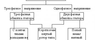
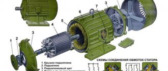
First, the required electric motor is selected: it must be low-speed (no more than 1300 min-1), having 3 or 4 pairs of poles.
Grooving the motor rotor for installing magnets
rice. 1
It consists of reducing the diameter of the rotor to the height of the installed magnets. Options are possible here: if the available magnets are not strong enough, then it is additionally necessary to grind and place an adapter metal sleeve on the rotor, with the help of which the value of the induced magnetic induction will be sufficient to prevent the dissipation of the magnetic field. Otherwise, no other work to modify the rotor is necessary. The rotor machined for installation of magnets (if there is a bushing) has the form shown in Fig. 1.
Calculation of the required number of magnets and their installation
To do this, first determine the circumference of the rotor after regrinding, which will correspond to the height of the bushing:
L=πD, where D is the rotor diameter.
The required magnet thickness t must be within t=(0.1…0.15)D. Next, the number of sections n is calculated, in each of which magnets will be installed with the same pole:
n=L/p, where p is the number of poles of the electric motor.
rice. 2
To finally resolve the issue, determine the number of magnets that can fit in one pole, so that they can then be distributed evenly and with the greatest density over the entire height of the bushing. The displacement of the magnets when sticking them is assumed to be equal to the thickness of one magnet. For gluing it is best to use epoxy glue. The appearance of the bushing with assembled magnets, mounted on the rotor, is shown in Fig. 2.
Checking the functionality of the generator
After assembling a wind generator from an asynchronous motor, it is necessary to check the actually developed output power, since after gluing the magnets, as well as due to an increase in the mass of the rotor, the parameters of the electric machine change. For this purpose, the generator rotor must be rotated at a speed corresponding to the rated rotation speed of the converted electric motor.
rice. 3
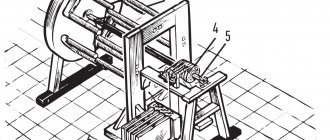
To do this, you can use a regular electric drill, and connect any available load at the output, for example, a light bulb. By changing the power of the connected lamps, as well as the number of revolutions of the drill, it is possible to establish the practical performance of the wind generator and the dependence of the generated voltage on the number of rotor revolutions. The control installation and its various connection options are shown in Fig. 3.
Manufacturing of the wind generator executive part
It should consist of propeller blades, a rotary axis and a stand on which the entire structure is fixed. The blades (see Fig. 4) can be made from polyvinyl chloride pipe with a diameter of 150...200 mm. Next, from an asynchronous motor for the finished wind generator , which must have a rotary axis assembled on rolling bearings. The finished design of the executive part of the wind generator with a propeller with a diameter of 1.7 m is shown in Fig. 5.
rice. 4
rice. 5
Wind generator based on an asynchronous motor
A wind generator is a fairly simple and reliable design in terms of a source of autonomous electrical energy. The type of generator described in this article operates on permanent magnets and is a converted model from an asynchronous motor. The generator is made from an old four-pole motor. Since this is the first attempt at such a transformation, the engine power did not matter here, rather it was a matter of practical application and pure interest. The first step was to disassemble the engine. I was surprised by the condition of the parts inside the structure - they were practically new, which couldn’t help but rejoice.
Now it was necessary to sharpen the rotor. Often, such work needs to be done only if you have turning skills. Since you don’t have such skills, you had to turn to a turner you know for help.
Next, it was necessary to select magnets and calculate the bevel of the magnetic pole. The bevel is made to prevent sticking. As soon as all the calculations were carried out, I immediately printed out the template and punched the holes.
This template is needed to show where exactly the magnets need to be glued. If you correctly calculate the bevel angle, then there should be no problems when gluing the magnet. Basically, such work will take no more than two hours.
Next, I tightly wrapped the rotor with tape. This should be done from below, smoothly moving upward. And only leave a gap at the very top. Next, I calmly filled it all with epoxy resin to achieve greater tightness and reliability. When the process of turning the rotor is carried out, it is necessary to take a reserve of 1.5 - 2 times more than the calculated one. The whole point is that if you don't grind enough, the rotor simply won't be able to enter. You can, of course, grind off the magnets, but in the future this can lead to overheating of the generator, so it’s better to take care of all the nuances in advance.
Now you should put the generator together and check its speed. Simply turn the rotor with two fingers. Turns should be easy, without sticking or friction. Now that the design is completely ready, you can begin the process of taking characteristics.
Naturally, during the first measurements it is impossible to guarantee the exact characteristics of the generator, but it is still enough to roughly estimate. After all the characteristics have been taken, you can begin to manufacture the blades.
According to the characteristics, it can be noted that the turbine diameter will correspond to 1.7 meters, and the speed will be Z 5.
Having manufactured the entire structure, it is necessary to check its functionality. It is enough to check its operation by replacing a regular weather vane. A small wind is enough here for the generator to come into action. Therefore, it is necessary to carefully install the structure instead of the weather vane and put it into operation. As already mentioned, the presence of wind will only add spectacular speed to this design, but the main thing is that at this time the generator is already secured.
This design can easily operate for several months, without repair or replacement of structural parts. Of course, provided that everything is done correctly. After several months of operation, the generator should be completely checked.
Author: Nagoryansky Alexander Alexandrovich .
We recommend:
What does it consist of?
- A rotor with blades and a wind turbine, equipped with a special tail for orientation against the wind or a wind wheel;
- A mast with or without guys on which the rotor is attached. Typically, masts are built with a height of 3 to 7 m;
- Rechargeable batteries (lead starter acid batteries are most often used);
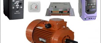
- AC electric generator for which an asynchronous motor is used;
- Device for monitoring battery charge (controller);
- A converter connected to a household network (inverter), with a power from 600 to 1500 W;
- Lightning removal system (grounding).
Stages
These works have practically nothing in common with each other, since it is necessary to make system components that are different in essence and purpose. For the manufacture of both elements, improvised mechanisms and devices are used that can be used or converted into the required unit. One of the options for creating a generator, often used in the manufacture of a wind generator, is manufacturing it from an asynchronous electric motor, which most successfully and efficiently solves the problem. Let's consider the question in more detail:
Types of wind generators
Wind turbines can differ in the following parameters:
- number of blades
- manufacturing materials
- orientation of the axis of rotation relative to the surface of the earth
- screw pitch sign
Multi-blade models are more efficient than two- or three-blade models because they are driven in the smallest air flows. The blades can be rigid or sail-like. Rigid ones are usually made of metal or fiberglass. In the direction of the axis of rotation, vertical and horizontal modifications are distinguished.
Wind generators with a horizontal axis of rotor rotation have become more widely used. Such installations are characterized by high efficiency, improved protection against hurricane gusts of wind and simple power adjustment. Vertical models are easy to install, silent and can operate even in light gusts of wind.
Model with neodymium magnets
Homemade wind generators using neodymium magnets are becoming increasingly popular in many Russian regions. As the basis for such a device, it is necessary to use a hub from a car with brake discs. It is better to disassemble the part and check for serviceability by lubricating the bearings and removing rust.
Neodymium magnets are glued to the rotor disks. For example, you can take twenty small magnets. When choosing the number of magnets, you need to remember that in a single-phase generator the number of poles must match the number of magnetic elements. For a three-phase model, this ratio can be 2 to 3 or 4 to 3. During the installation of magnets, you need to alternate their poles. To avoid mistakes, it is advisable to use rectangular magnets. To attach magnets you need to use the most reliable glue.
A video on assembling such a generator can be viewed here:
A magnetic generator will work efficiently if the stator coils are correctly sized. It is known from experience that to charge a 12 V battery, about 1000 turns should be equally distributed in the coils. The coils are wound with thick wires to reduce resistance. The wind generator mast must be six meters or more in height. You need to dig a hole under the mast and then pour concrete. The blades for the device are made of polyvinyl chloride pipes.
Model from a car generator
A homemade wind generator from a car generator must be made from components (battery, relay, etc.) from one car. At the same time, to create a windmill, it is better to use a car generator from powerful equipment (for example, from a tractor).
Since consumers need alternating current, it is necessary to provide an inverter or converter. In regions with high wind speeds, wind generators can be installed to generate greater power.
To assemble this model you will need the following:
- 12V car generator
- battery
- voltmeter
- battery charging relay
- blades
- fastening material
First, the rotor is made. The optimal solution would be to create a rotor wheel of four blades. This element is made from sheet iron. If possible, you can use an iron barrel.
The finished windmill is connected to the generator axis. To do this, a hole is drilled and the connection is secured with bolts. After this, the electrical circuit is assembled and the mast is installed. Then you need to secure the car generator with wires that connect to the battery and voltage converter. For proper assembly, it is better to use prepared drawings.
Such an installation can be installed quickly enough without any particular difficulties. This wind generator is good for its simplicity, reliability and silent operation.
A video of the assembly of such a wind generator can be viewed here: