A microwave works in almost every modern apartment. This convenient household appliance can heat, defrost, and bake. Some models are capable of grilling and executing complex programs to create finished dishes inside. The operating principle of a microwave oven has not changed since its invention. But thanks to technological progress, the safety of the equipment has increased, and the electrical circuit is capable of complex control and precise control of operating parameters.
General operating principle of a microwave oven
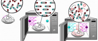
The physics of the process of heating the contents of a microwave oven is quite simple. Microwave radiation affects the molecules of products, and due to their mutual friction, heat is released. But this is too simple an explanation.
In fact, only water molecules undergo vibrations. But if you put an ideally clean glass of distilled liquid in the microwave, its temperature will change quite little during the standard operating time of the oven. So why do foods heat up? This occurs due to the friction of molecules at the boundary of media, that is, different substances. And since the structure of any material, be it an edible product or a piece of wood, is large and necessarily contains water in the structure, fluctuations of different amplitudes arise.
Important! The frequency of the microwave oven is designed to have maximum effect on the molecules of the liquid. It is they, with their intense vibration and friction against neighbors, that contribute to the release of large amounts of heat. Materials that are dry and pure in chemical composition heat up very slowly, but there are few of these in nature.
Metals should not be placed in the microwave. When exposed to microwave radiation, surface currents are formed and spark and arc breakdowns occur on the walls of the internal compartment of the furnace. However, technological progress has found a way out. Today, many companies, such as Daewoo, produce microwave ovens in which metal objects can be placed. Also, many models allow the use of closed contours, in particular, plates with foil stamping on the edge or decorative dishes with a metal edge.
What elements are included in the design of a microwave oven?
The design of a microwave oven seems complicated only at first glance. The owner of this device is misled by the number of buttons, indicators, and programming tools. In fact, any oven, with mechanical control, touch panel, remote control, hybrid electronic control, consists of the same functional blocks:
- microwave radiation generation unit, magnetron and waveguides;
- voltage conversion system, main module - step-up high-voltage transformer;
- control means as part of a group of sensors;
- secondary protection system;
- microwave control circuit.
Important! Depending on the complexity of the stove model, it may include a variety of options. For example, a grill, secondary wave scatterers, additional microwave generation units.
It is worth considering the operation of each unit separately, in the order in which they are used in a standard microwave usage scheme.
Control circuit
The main electrical circuit of the microwave that the user deals with is the control unit. In it, using buttons, mechanical switches, and regulators, boundary parameters are set. That is, operating power or mode, program execution time, and so on.
The control scheme can be as complex as you like. The simplest option is circular regulators, one of which is a timer relay. With their help, the mode power and operating time are set. Another option familiar to users is a hybrid one, with buttons. In fact, its functionality is not much wider than mechanical adjustment.
The touchpad, in most cases, is no different in principle from buttons. It is simply more reliable and requires no maintenance. Advanced electronic control circuits include programming, that is, switching according to a given algorithm of the radiation power and the time of its output.
Voltage conversion system
The microwave consists of a group of components that are very dangerous for humans. The main one is the step-up transformer. When the control circuit commands the mode to turn on, it produces up to 4 kV voltage. In this case, the operating current can reach 10A and higher. Such parameters of the electrical network pose a huge danger to humans.
Important! The step-up transformer is the key and most expensive component of the voltage conversion system. It powers the magnetron, an element without which it is impossible to implement the basic principle of operation of a microwave oven.
Microwave radiation generation unit
The magnetron is the heart of the microwave. In fact, this is an ordinary vacuum tube, similar to those that were used in picture tubes of old televisions. Only the magnetron generates an intense, high-frequency electromagnetic wave produced when electrons pass through a magnetic field.
The radiation generation unit consists of more than one microwave source. To, so to speak, supply waves to the working area of the furnace, waveguides are installed. They are the ones behind the mica plate that everyone saw on the side wall of the microwave when they put a plate of breakfast in it.
Primary and secondary protection systems
The role of control sensors is quite clear. They make sure that none of the key electronics and hardware elements reach critical operating conditions. Sensors guarantee trouble-free operation of the device and prevent dangerous malfunctions. But microwave ovens have safety systems designed for humans. Their functions will be described in detail below.
So, the control system initiates the start of the magnetron. It also sets operating parameters, counts time intervals, changes power, and so on. There is also feedback between the security and control systems. Based on the signals of the former, the operation of the furnace can be completely stopped, the mode can be changed, a service message or sound alerts can be issued.
How does a microwave work?
Components of a microwave oven:
- Camera. Made of metal. Equipped with a metallized door. Microwave radiation is concentrated here. This is where food is placed to be heated. Requires care.
- Magnetron. High frequency microwave emitter.
- Transformer. Magnetron power supply.
- Communications and control system.
- Waveguide. Transmits microwaves from the emitter to the chamber.
Additional details:
- Pallet. By rotating, it promotes uniform heating of the cooking objects.
- Fan. For ventilation of the chamber and cooling of the magnetron.
The operation of a microwave oven comes down to the release of energy by a magnetron, which is converted into heat. The device is connected to a transformer-stabilizer. Once this device was the most expensive in the microwave oven, today its cost has decreased and microwave ovens have become much more affordable.
The basic electrical circuit of all microwave ovens is almost the same, only their characteristics, capabilities and design are different.
What is a magnetron
Its purpose is to generate radiation of a given frequency. Essentially, this is an electric vacuum diode. Its structure:
- It has a cylindrical anode. It has a round cross-section and ten sectors with copper walls.
- In the center of the diode is the cathode. Inside it is a glowing filament. The function of the cathode is to emit electrons.
- At the edges of the magnetron there are ring-shaped magnetic elements. Their task is to create a magnetic field in the emitter. This field is a generator of high-frequency waves.
- The voltage applied to the anode is 4000 V and to the cathode filament is 3 V.
Due to the voltage difference, the cathode emits electrons, which are trapped by a high-strength electric field. The generation frequency depends on the configuration of the resonator chambers and on the anode voltage.
The energy is removed through a loop of wire, which is connected to the cathode and output to the radiating antenna. Radiation from the antenna is directed to a waveguide, through which it passes into the microwave oven.
Conventional microwave ovens use magnetrons with a power of 0.8 kW. Sometimes, to prepare a dish, you need power less than 0.8 kW, then the device turns on for short periods of time, interspersed with pauses.
This operating principle is known as pulse width modulation. Since the magnetron heats up while operating, it is placed in a plate-type radiator, which is constantly blown by a fan. Overheating may cause damage. To prevent this from happening, install a special thermal fuse.
What does a thermal fuse consist of?
These devices are also known as thermal relays. They are produced for different temperature ratings.
The thermal relay consists of an aluminum housing, which is attached to the temperature control point with a flange connection, and a bimetallic plate set to a certain temperature value. When the heating exceeds the permissible threshold, the plate, bending, triggers an element that opens the contacts - the power to the stove stops.
When the magnetron cools down, the bimetallic plate will take its original shape and the contacts will close - the furnace will turn on.
Microwave wave distribution schemes
First, it’s worth focusing on the operation of the microwave generation unit. The structure of the magnetron consists of a radiating element and a winding that generates a magnetic field. This lamp, roughly speaking, is constantly wearing out. Everyone has encountered a situation where, as use progresses, the microwave heats up less and less. This is a normal phenomenon; every model sooner or later requires replacement of the magnetron.
Furnaces from different manufacturers (or levels of complexity) may use different microwave wave distribution schemes. In the standard solution used by LG and many other manufacturers, only one waveguide goes from the magnetron to the product area. It is covered with a mica plate to prevent debris and steam from entering.
Important! Models with a single waveguide, which emits a fairly localized stream of waves, use a reflector on the opposite side of the product compartment. This is the concave zone of the wall. It helps distribute microwave radiation more evenly throughout the working volume.
Some Samsung microwaves use a different principle: a main waveguide and several slot antennas are installed. This allows you to evenly distribute the energy flow, forming so-called 3D radiation. In addition, the oven, by varying the power of the magnetron, achieves smooth heating of the products throughout the entire volume.
But the most important thing in generating microwave waves is their parameters. The radiation frequency of the magnetron in the microwave is 2.45 GHz - this is the value that is resonant for water molecules, causing them to vibrate with a large amplitude. The product is heated. Heat from the surface layers gradually spreads throughout the entire volume of the product.
There are some solutions to speed up the heating of food in the oven work area. These are the so-called dissectors. In appearance, such a structural element is similar to a fan on the ceiling of a microwave oven. However, it does another job, namely, it scatters microwave waves.
Other functional elements of the furnace have a completely understandable purpose. For example, a microwave oven with a grill affects food not only with microwave radiation, but also with infrared radiation. It allows you to achieve a beautiful baked crust on your food. Some stove models can be equipped with additional fans to remove heat.
General device
In principle, it is convenient to present the design of a microwave oven in a simplified picture.
Food is heated in the cooking chamber under the influence of high-frequency electromagnetic radiation. It is created by a magnetron and directed to the food through a waveguide.
A programmer with a power regulator, through a control device module, influences the high-voltage voltage supplying the source of microwave radiation and thus ends the technological cycle.
Electrical circuit composition
The structure of the microwave electrical equipment is fundamentally highlighted in the picture with color blocks:
- filter to reduce high-frequency interference sent to the power supply network;
- control module with a pulse generation device;
- high voltage transformer;
- magnetron circuits;
- three-wire power cable with a grounding conductor.
We will discuss possible causes of malfunctions in these units below, but first we will consider their placement inside the case.
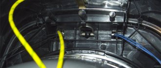
Assembly of units
Before removing the cover from the device body, it is necessary to disconnect the equipment from the mains supply voltage and take measures to discharge the high-voltage capacitor.
A magnetron is located in the center of the microwave oven. On the top right you can see the surge protector, which is supplied with 220 volt power via a three-wire circuit.
The control module is mounted on the left in the middle. Electromechanical blocking limit switches control the position of the microwave door with a protective filter that blocks microwave radiation from entering outside the chamber during operation.
The transformer, with its high-voltage part of the circuit with a diode, fuse and capacitor, provides supply voltage to the magnetron, which becomes very hot during operation.
To reduce the temperature, a cooling system has been created that operates on the principle of air flow.
The rotating fan impeller creates a wind flow through the magnetron cooling radiators and dissipates heat into the room through the holes. In the same way, the temperature of the convector is reduced.
The location of the thermal fuse and surge protector with the power cable input is shown in the top view.
How the protection system works
It is also worth covering in detail the functioning of security systems. They are divided into two significant groups.
- Monitoring hardware parameters. These are the magnetron temperature sensor, fuses, cooling fans. They solve the problem of blocking potential emergency situations and maintaining normal electronic performance indicators
- Protection of humans from electric shock and microwave radiation.
Anyone who has ever disassembled the body of their microwave has encountered electric shock protection systems. Microswitches are located at key installation points. Once the lid is removed, the stove can no longer be turned on. The security system simply will not allow this.
But more interesting is the scheme for neutralizing microwave waves. It is worth understanding that radiation, even theoretically, cannot be localized inside the furnace chamber. Waves are reflected, including from products. Therefore, glass with a thin metal grille applied to it is installed on the front door. This is an antenna module. It is connected to a spark gap, which releases the accumulated energy by surges into the main electrical network of the device.
Important! The microwave generates wiring noise. In some homes, this can be detected by the operation of other devices (in particular, Wi-Fi routers), especially if a frankly cheap stove with poor noise reduction is used.
Microwave electrical circuit
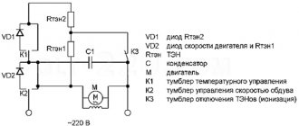
Based on the above, it is not difficult to understand how a microwave oven works simply by looking at it from the outside, looking into the chamber and at the rear. But if you want to fix something, it is useful to understand in general terms how the nodes interact with each other. A schematic diagram of a microwave oven will help with this. Its structure seems complicated only at first glance. However, any circuit consists of basic blocks. As an example, it is worth looking at the device of a model with mechanical analog control.
The diagram clearly shows how energy is converted and security systems operate. One of the very first circuits is always the noise suppressor (NOISE FILTER). It is this that dampens the vibrations generated by the energy discharger in the door, protecting people from high-frequency radiation.
Next comes the main security system. This is a block of contacts in the door, one monitors the fit to the body, the second the position of the latch, the third the position of the handle. If any of them is open, the oven will not work.
The third functional block is drives and lighting. Everything is simple here. A constant voltage is supplied to the motor that rotates the plate, the fan and the lamp. The timer opens the circuit when the set time interval ends.
The last operating circuit is a step-up transformer, a magnetron temperature control sensor, its breakdown protection system and a fuse. And the scheme always ends the same way. The main working part of the furnace is the magnetron.
Automation system
The operating principle of a working microwave oven is as follows:
- Food to be heated is loaded into the chamber, the door is closed with the plug plugged into the socket (three contacts of the electromagnetic lock have been activated) and the timer control is turned - the SW limit switch is closed. Power is supplied to the backlight, electric motors of the timer, fan and turntable.
- When the engines enter operating mode, limit switch SW2 connects the pulse-forming device to the high-voltage transformer, which begins to power the magnetron. The food is heating up.
- The end of the timer operation time ends with the opening of SW1 and SW2, which leads to the switching off of microwave radiation and stopping the engines. At the same time, an audible alarm sounds.
Timer
Structurally it includes:
- the timer itself, which performs the function of counting the time specified by the user (a mechanical watch with a spring or a micromotor with a gearbox) and carries out technological operations using it;
- power regulator.
The most common scheme: an electric motor rotates a cam mechanism through a gearbox with a branched contact group that works to connect or open circuits.
The following manifestations of timer defects are often encountered:
- The automation does not respond to turning the control handle, the microwave does not turn on, and returning the handle back is difficult. Possible reasons: clogging of the kinematic circuit, breakdown of the engine or gearbox;
- failure of final functions, when after turning on the backlight and spinning up all electric motors, irradiation of the internal space with microwave rays does not occur. Reason: contact SW2 failure or its cam is broken;
- the control knob works, returning back after a set time, a bell sounds, but the backlight does not turn on, and the electric motors do not start, there is no heating of food. Malfunction of limit switch SW1;
- automation operates with an increased response time. The compression force of the clock mechanism spring has weakened. It needs adjustment.
Kinematics of the working chamber
Fat vapors can accumulate on the convector and the rotating elements of the work table, causing uneven movement. This leads to defects when overheated areas are created that turn into fistulas in the microwave tract.
Therefore, the uniformity of the table movement and the cleanliness of the waveguide surface must be controlled, and you should not disassemble the microwave path or magnetron yourself. This is work for a service center, and its cost is quite reasonable.
Microwave pulse generation circuit
We return to the electrical circuit of the microwave and see that through current-limiting resistors R2+R3 with diode D1, capacitor C4 is charged and voltage is supplied from it to the relay winding RY. Zener diode D2 limits the potential difference across it.
Due to this, a cyclic supply of voltage occurs to the relay winding from C4, which leads to the activation of the RY contact and the discharge of the electrolytic capacitor, after which it begins to charge again.
When the relay is triggered, its contact connects a voltage of 220 volts to the input winding of a high-voltage transformer, which powers the magnetron in pulse mode.
The heating power of microwave rays can be adjusted by changing the resistance of current-limiting resistors R2+R3 or bypassing one of them. In this case, the time of supply of the high-voltage pulse to the magnetron and, accordingly, the duration of its irradiation or output power changes.
Due to electrical processes, electromagnetic energy is constantly accumulated in the transformer. When switched off abruptly, it is capable of generating a powerful burst of microwave radiation from the magnetron, which can burn through a chamber or waveguide.
To eliminate such a defect, the primary winding is connected in parallel to resistances R4. Without them, the microwave will become dangerously emitting microwave radiation, and a reduction in their rating is quite possible, for example, due to contamination with a fatty layer. The duration of the pulses immediately increases. They will lead to general overheating and the microwave will turn off at the upper temperature limit in the chamber.
Some models of microwave ovens use a complicated mode for creating magnetron power pulses by installing additional cams with contacts on the timer shaft, which additionally regulate the radiation power.
Possible faults
Relays and capacitors are most susceptible to damage.
Relay defects
The pulse-forming device mechanically operates a relay switching contact that constantly switches fairly high currents. Due to the loads created, it is most often the cause of microwave failure.
The functionality of the relay is checked by applying/removing a voltage of ±24V to its winding. A tester is connected to the contact in ohmmeter mode.
Based on its readings, they judge the closure/opening of the created chain and the serviceability of the relay module.
A faulty relay should be replaced. Its body is non-demountable and cannot be repaired.
Capacitor defects
- Any electrolytic capacitor is prone to drying out of the insulating layer and loss of capacity during operation. When this happens with C4, the heating of microwave radiation in the working chamber weakens, and the power of the microwave decreases.
- When large currents flow through the electrolyte, it boils, releases and accumulates vapors inside the housing, followed by an explosion—the microwave stops working.
The cause of the malfunction may be a breakdown of diode D1 or zener diode D2. In addition to checking them, it is also necessary to evaluate the performance of the RY relay, the winding of which was exposed to increased voltage.
Magnetron connection
A half-wave high-voltage rectification circuit is used for power supply. In this case, the transformer output is designed to operate in short circuit mode of the output winding for at least five minutes.
The principle of operation of the multiplier is the same as that of old tube TVs: the positive semi-harmonic of the sine wave via VD2 charges C1 to an amplitude of 2 kV, and the negative one charges it to 4 kV. The magnetron begins to generate a pulse, discharging C1 and the 4 kV supply process resumes.
The high-voltage fuse FU2 protects the magnetron from overheating caused by turning on the microwave with an empty working chamber or metal objects loaded into it, as well as in cases of breakdown of the high-voltage diode.
Discharge resistor R1 partially reduces the potential of the microwave pulse when the user opens the microwave door while heating food. R1 reduces the irradiation pulse.
Diode VD1 provides additional protection for certain models of microwave ovens. It reduces the electric arc that occurs when a high-voltage fuse blows, the energy of which additionally powers the magnetron, causing a burst of microwave radiation.
The protective diode and fuse are designed for one-time use and must be replaced after tripping. The serviceability of capacitor C1 is determined by measuring its capacity during charging. The performance can be partially assessed by the value of capacitance to alternating current.
Any malfunction in the magnetron power circuit causes the microwave to fail.
Magnetron damage
The state of its electrical circuit can be checked with an ordinary tester by switching it to ohmmeter mode.
Internal short circuit
It can occur due to peeling of the cathode coatings, which creates a short circuit to the anode.
Damage to the cathode filter
It consists of two pass-through high-voltage capacitors and can be broken down by voltage. It is necessary to check its electrical resistance with an ohmmeter. A filament is connected to it, heated by a current of 10 amperes at a supply voltage of 6.3 volts. When the filament is cold, the total resistance of the filter and the filament circuit will be close to zero.
The filter capacitors cannot be disassembled. Their insulation material is toxic.
Next, you can remove the holder of the pass-through switches without disassembling the magnetron and disrupting the microwave radiation path. Typically, an insulation breakdown is visible to the eye. But there may also be a hidden defect that creates a leakage current into the energized housing. It can be identified by special measurements.
Loss of cathode emission
The reason may be depressurization of the housing structure, when instead of vacuum there is air inside: the magnetron will not work.
It is also possible to demagnetize permanent magnets that create a deflection field for electrons. It occurs from overheating at high temperatures.
How to check the magnetron power transformer
When doing repairs yourself, you need to make sure that the high-voltage part of the transformer is in good condition and call its electrical circuits. Checking the integrity of the fuse and connecting wires is performed with a tester in ohmmeter mode. And determining the serviceability of the windings for breaks and the absence of interturn short circuits can cause difficulties.
The active resistance of the high-voltage winding is quite high; the battery voltage of the tester is not enough to perform the measurement. There are various tips on the Internet, for example, connecting 220 volts to it through a 15-watt incandescent light bulb. This method will reveal the integrity of the wire, but will not detect an interturn short circuit.
Metering method through inverse transformation
This is a simple and effective method, but it must be used carefully and carefully, observing the necessary safety measures and being sure to break the high-voltage output circuit to the magnetron. This can be done by removing the fuse from the circuit, covered with a cover with high-strength insulation. The second end of the winding wire is connected to the transformer body. It's better not to turn it off.
The method is based on the dependence of the output voltage on the number of operating windings. This indicator is called the transformation ratio. For our case, it is equal to 2000 V/220 V≈9.1.
For a working transformer, the ratio of the number of turns and voltages on the windings differs by 9.1 times. If 220 volts are supplied to the high-voltage side, then the power winding should have 220/9.1≈24.2 V. Naturally, the measurement should be performed at idle, that is, with the circuit loads turned off. And the power supply to the home network can fluctuate within wide limits and is controlled by the operation of the voltage relay.
The integrity of the winding of the magnetron filament heating circuits up to 6.3 V can also be determined by measuring the output voltage. Do not forget about safety and the need to break the high-voltage circuit.
Self-made test method
The multimeter is switched to voltmeter mode at the scale limit of ≈750 volts. Its input resistance in this position is several megohms.
Through it, the phase potential wire is supplied to the winding circuit of the transformer being tested. Zero is connected with a separate conductor.
As a result of the check, data summarized in a table can be obtained.
| Scoreboard readings | Type of defect |
| Value around input voltage | The winding being tested is short-circuited |
| Voltage of several tens of volts | Insulation breakdown at operating voltage |
| Voltage of several volts | Leakage current at operating voltage |
It is almost impossible to repair a failed high-voltage transformer with your own hands, but it is easy to make a resistance welding machine from it, which will make it easier for the home craftsman to perform various tasks.
Cooking chamber and wave guide
During repairs, attention is paid to the cleanliness of the internal surfaces, the uniform movement of the worktable, and the condition of the waveguide, resonator and emitter.
Condition of internal surfaces
The issue of maintaining cleanliness in the cell has already been addressed. If layers of fumes form on the surface, they should be removed with detergents recommended by the manufacturer. At the same time, the formation of scratches no deeper than 1/10 mm is monitored by eye.
Burn-through of the coating is unacceptable. It is completely impossible to repair them in such a way as to eliminate the “siphon of microwave radiation”. The stove is rejected for safety of use.
Checking the turntable
The desktop is assessed by hand for smooth rotation. If violations are detected, mechanical cleaning is carried out.
Waveguide Cleanliness
Contamination appears visually: when the microwave operates, sparks begin to appear inside the chamber. It is necessary to carefully remove the protective cover from the waveguide window and inspect it. It is made of mica fabric or a layer of mica, is fragile, and breaks if handled carelessly.
From the outside, mica may seem clean, but on the opposite side, under the influence of microwave radiation, due to settled fat vapors, destruction of the coating occurs, leading to the creation of sparks. The mica cover must be replaced with a new one from the manufacturer.
The use of random mica coatings is unacceptable. It disrupts the thermal balance in the chamber, reduces the resource, and provides a “siphon of microwave radiation.”
Output resonator and magnetron emitter
A resonator is visible under the mica cover of the working chamber. Its working surface can be treated with alcohol. When traces of cracks, swelling and overheating are noticeable, the magnetron needs to be replaced.
If darkening is detected on the emitter, it is replaced with a new one. The old one is taken out of the nest, and if it has become stuck, then carefully turn it with small pliers and remove it. A new one is taken only with a latex glove to protect the skin of the fingers from scratches and dirt.