Dear visitors!!!
The presented topic answers the following questions:
- how to repair a Samsung vacuum cleaner;
- how to repair an Lg vacuum cleaner;
- how to repair a Thomas vacuum cleaner;
- how to repair a Zelmer vacuum cleaner
and other vacuum cleaners from different manufacturers.
Regardless of the manufacturers of such products as a vacuum cleaner, they differ only in their design and quality. Of course, to resolve this issue, you need to know the electrical wiring diagram of the elements. Let's look at three electrical circuits of vacuum cleaners.
Electrical circuit of a vacuum cleaner
I found this electrical diagram (Fig. 1) on the Internet, where it was explained that this diagram applies specifically to a vacuum cleaner.
rice. 1
The switch in this diagram (Fig. 1) is a disconnector with two poles \phase and zero\. Two chokes Dr1 and Dr2 are connected in series in the electrical circuit, capacitor C3 in parallel. The remaining two capacitors are connected in series. The stator of an electric motor consists of two field windings. The electrical circuit is closed through the graphite brushes on the rotor commutator.
To be honest, in my practice of repairing vacuum cleaners, I have never seen such schemes. Therefore, I have provided you with my own diagrams, according to which I had to troubleshoot vacuum cleaners of various models.
rice. 2
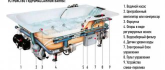
In my home I use a DAEWOO vacuum cleaner (with dust bag). The design of the vacuum cleaner is simple. The vacuum cleaner was given to us by friends who thought that the vacuum cleaner was faulty. Ultimately, a little maintenance was done (lubricating the bearings), the vacuum cleaner is already about five years old, and it works properly. The diagram (Fig. 2) gives the following designations:
R.O - working stator winding,
P.O - stator starting winding,
Off - push-button switch,
S.p - starting capacitor.
The circle in the diagram located between the two stator windings is the rotor of the electric motor. The capacitor and switch in the circuit are connected in series, the ends of the two windings are also connected in series. The circuit is presented as connecting an asynchronous motor through a capacitor. Of course, vacuum cleaners have AC commutator motors. Therefore, I want to say that two electrical diagrams (Fig. 2, Fig. 3) provide an explanation for connecting a capacitor, two stator windings, and also how the speed of the vacuum cleaner motor is adjusted. Consider the following diagram of a vacuum cleaner with an electric motor speed controller.
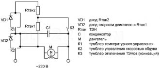
AUTOMATIC CONTROL SYSTEM FOR ELECTRIC VACCUUM CLEANER
Purpose of work: Studying the circuit diagram of the automatic control system for the electric motor of a vacuum cleaner.
The engine speed controller used an existing one, supplementing it with a homemade circuit to automatically start the vacuum cleaner when the power tool is turned on.
Figure 3 — Diagram of the automatic control system for the electric motor of the vacuum cleaner
Automatic devices (2-pole) QF1 and QF2 protect, respectively, the circuits for connecting power tools (socket XS1) and the speed control circuit of the vacuum cleaner engine. When the tool is turned on, its load current flows through diodes VD2-VD4 and VD5. They were selected from the reference book due to the large voltage drop across them with forward current. On a chain of three diodes, when one (let’s call it “positive”) half-wave of current flows, a pulsating voltage drop is created which, through fuse FU1, Schottky diode VD1 and resistor R2, charges capacitor C1. Fuse FU1 and varistor RU1 (16 Volt) protect the control circuit from damage due to overvoltage, which can occur, for example, due to a break (burnout) in the chain of diodes VD2-VD4. The Schottky diode VD1 is selected with a low voltage drop (to “save” the already small Volts) and prevents the discharge of capacitor C1 during the “negative” half-wave of the current through the diode VD5. Resistor R2 limits the charging current of capacitor C1. The voltage received at C1 opens optocoupler DA1, the thyristor of which is connected to the control circuit of the engine speed controller. Variable resistor R4 for regulating the motor speed is selected with the same value as in the vacuum cleaner controller board (it is removed) and is made remote (in the housing from the dimmer) for placement on the top cover of the vacuum cleaner. A resistor R removed from the board is soldered in parallel to it. The “on/off” switch S2 in the open circuit of the resistor R4 is used to manually turn on the vacuum cleaner. Switch S1 “automatic/manual”. In manual control mode, S1 is turned on and the regulator current flows through the chain R4 (R) - S2 is turned on - S1. In automatic mode, S1 is turned off and the regulator current flows through the chain R4 (R) – pins 6-4 DA1. After turning off the power tool, due to the large capacity of capacitor C1 and the inertia of the motor, the vacuum cleaner continues to work for about 3-5 seconds. This time is enough to draw the remaining debris from the hose into the vacuum cleaner.
QUESTIONS TO CHECK STUDENTS' KNOWLEDGE
1. What motor is used in the electric drive of the vacuum cleaner?
2. What are the QF1 and QF2 machines intended for?
3. Explain the operating principle of the automatic control system for the electric motor of a vacuum cleaner.
4. Show the path of current flow through the stator windings of the motor when the start button is pressed
5. Explain the purpose of VD2-VD4 and VD5 and what current flows in them?
6. What is the purpose of the vacuum cleaner regulator?
7. Explain the purpose of resistors R2 and R4.
HIGH-VOLTAGE POWER SUPPLY FOR MICROWAVE MAGNETRON
Purpose of the work: Studying the circuit diagram of the high-voltage power supply for the magnetron of a microwave installation.
The high-voltage power supply of the magnetron M (Fig. 4) consists of a transformer TP, a capacitor C and high-voltage diodes V1, V2.
Figure 4.- Schematic diagram of the high-voltage unit
magnetron power supply
Often there is also a fuse diode, the purpose of which is to protect the microwave from voltage surges in the network. To prevent the microwave oven from operating with the door not tightly closed, interlock microswitches are used. Depending on the type of microwave oven, there are from 2 to 5 pieces. Lighting in the chamber is provided by an incandescent lamp, usually located inside the duct. The furnace operating mode is set using a control unit - a power control unit. The latter can be made either in the form of an electromechanical timer or in the form of an electronic unit, usually based on a microcontroller. To prevent interference from a working microwave oven into the external network, a surge protector is used, which also contains one or two fuses. To prevent the furnace from failing due to overheating, many of them have thermal relays, which are usually located on the magnetron and on the outside of the chamber.
QUESTIONS TO CHECK STUDENTS' KNOWLEDGE
1. What components does the high-voltage magnetron power supply consist of?
2. The operating principle of the electrical circuit of the high-voltage power supply of the magnetron of a microwave installation.
3. Show the path of current flow through the stator windings of the motor when the start button is pressed
4. Explain the purpose of high voltage diodes V1 and V2
5. Explain the purpose of the TP transformer.
6. Explain the purpose of capacitor C.
1
What Causes Trends in Stock and Commodity Markets Freight Train Theory Explained My first 17 years of market research consisted of trying to figure out when...
What does the IS operation and maintenance department do? Responsible for the safety of data (copying schedules, copying, etc.)…
WHAT HAPPENS IN ADULT LIFE? If you are still connected to your mother in the wrong way, you are avoiding separation and independent adult existence...
WHAT AND HOW THEY WRITTEN ABOUT FASHION IN MAGAZINES AT THE BEGINNING OF THE XX CENTURY The first issue of the Apollo magazine for 1909 began, in fact, with a policy statement from the magazine’s editors...
Didn't find what you were looking for? Use Google search on the site:
Various types of electric motors
Various electric motors are used in technology. And the choice of diagnostic method depends on the type of engine. Examples include the following electric motors:
- vacuum cleaner motor: asynchronous (two phases - alternating current) capacitor;
- screwdriver motor, angle grinder, etc. – collector (alternating current).
In the first case, diagnostics are quite simple. As a rule, these motors have only two windings. Therefore, in order to check the correct functioning of the engine, it will have to be disassembled.
We test the coils using an ohmmeter (switch the multimeter to the required mode). The resistance of the working winding should be 50% less than that of the starting winding. Be sure to test the coils for breakdown on the body. This resistance must be very large.
If the indicator is small, you will have to rewind the stator.
Asynchronous or collector: how to distinguish
In general, you can distinguish the type of engine by a plate - a nameplate - on which its data and type are written. But this is only if it has not been repaired. After all, anything can be under the casing. So if you are not sure, it is better to determine the type yourself.
This is what a new single-phase capacitor motor looks like
How do collector motors work?
You can distinguish between asynchronous and commutator motors by their structure. The collectors must have brushes. They are located near the collector. Another mandatory attribute of this type of engine is the presence of a copper drum, divided into sections.
Such motors are produced only as single-phase ones; they are often installed in household appliances, as they allow one to obtain a large number of revolutions at the start and after acceleration. They are also convenient because they easily allow you to change the direction of rotation - you just need to change the polarity. It is also easy to organize a change in the rotation speed by changing the amplitude of the supply voltage or its cutoff angle. That is why such engines are used in most household and construction equipment.
Commutator motor structure
The disadvantages of commutator motors are high operating noise at high speeds. Remember a drill, an angle grinder, a vacuum cleaner, a washing machine, etc. The noise during their operation is decent. At low speeds, commutator motors are not so noisy (washing machine), but not all tools operate in this mode.
The second unpleasant point is that the presence of brushes and constant friction leads to the need for regular maintenance. If the current collector is not cleaned, contamination with graphite (from brushes being worn out) can cause adjacent sections in the drum to become connected and the motor simply stops working.
Asynchronous
An asynchronous motor has a stator and a rotor, and can be single or three-phase. In this article we consider connecting single-phase motors, so we will only talk about them.
Asynchronous motors are characterized by a low noise level during operation, therefore they are installed in equipment whose operating noise is critical. These are air conditioners, split systems, refrigerators.
Structure of an asynchronous motor
There are two types of single-phase asynchronous motors - bifilar (with a starting winding) and capacitor. The whole difference is that in bifilar single-phase motors the starting winding works only until the motor accelerates. Afterwards it is turned off by a special device - a centrifugal switch or a start-up relay (in refrigerators). This is necessary, since after overclocking it only reduces efficiency.
In capacitor single-phase motors, the capacitor winding runs all the time. Two windings - main and auxiliary - are shifted relative to each other by 90°. Thanks to this, you can change the direction of rotation. The capacitor on such engines is usually attached to the housing and is easy to identify by this feature.
You can more accurately determine the bifilar or capacitor motor in front of you by measuring the winding resistance. If the resistance of the auxiliary winding is twice as large (the difference can be even greater), most likely this is a bifilar motor and this auxiliary winding is a starting winding, which means that a switch or starting relay must be present in the circuit. In capacitor motors, both windings are constantly in operation and connecting a single-phase motor is possible through a regular button, toggle switch, or automatic machine.
High-tech robotic vacuum cleaners
Robot vacuum cleaners only appeared about 10 years ago. Their designs are constantly updated and improved. The devices are created according to a block design. This ensures ease of maintenance and ease of replacement of parts during repairs.
Common elements of a robot vacuum cleaner that are found in all models:
- side brush;
- block module;
- charging base;
- sensors for detecting obstacles, pollution, height differences.
The operation of such a device is based on a cleaning unit, navigation, drive mechanisms and a battery device.
Gadget navigation systems
The state-of-the-art navigation system consists of a laser, camera, internal and external sensors. The camera reads a map of the room. Rangefinder lasers transmit information to her about the presence of objects in the room and the distances between them.
The device moves in straight lines both during cleaning and during the process of returning to the base.
Robot vacuum cleaners do not yet know how to go down stairs or overcome high thresholds. Developers are trying to eliminate this defect in gadgets by inventing new models.
There are still models on sale whose operating principle is based only on sensors. They are located on the outer body of the device and inside it.
With their help, the robot navigates in space and adjusts its work, and also notices the most contaminated areas and is more careful in cleaning them.
Magnetic tape can also be used to navigate the robot. It creates a virtual barrier beyond which the device does not move. If the cleaner is equipped with a camera, it takes readings from the ceiling and walls.
Cleaning process
Here, the models differ in types of cleaning - dry cleaning and washing robotic vacuum cleaners. In the first, the side brush picks up all the dirt and directs it to the central brush. The central one has a fleecy surface and is capable of collecting hair and wool.
The design of the front brush of the robot is installed with an inclination into the device, and the side one has flexible wires, which ensures thorough collection of debris
Then these two parts send the garbage to the dust collector, where it is compressed by air currents. And the air passes through the filters to the outside.
Depending on the manufacturer, robot designs differ in the following nuances:
- Basic brushes . Most models have two of them - fleece and rubber. They work in pairs. Some devices are equipped only with rubber.
- Side brushes . There are devices that have an additional side brush built into them.
- Filters . The robots are equipped with both standard “napkins” and multilayer HEPA.
- Container + engine power . The waste collection container can have a volume from 0.4 to 1 liter. The power of such devices is 40-65 watts. If the first numbers are important during operation, then the second ones are unimportant due to the small range.
The main consumer part of robotic vacuum cleaners is the main brush. The quality of cleaning depends on it, and not on the engine, as with conventional units.
A wet vacuum cleaner has in its design a system of a water tank and a sprinkler. It can collect debris, spray liquid, polish the floor and collect dirty water back into the reservoir.
There are robot models designed for mixed cleaning. The principle of their operation is to clean smooth surfaces with a rag, and carpet surfaces with basic brushes.
Return to base
The final stage of the robot’s work is its return to the mother base. The device is powered by batteries. If they are discharged, the device turns off.
There are robots with a program that leaves the device at the cleaning site, and the user forces the return to the base
The device automatically reacts to a low charge percentage. Using a special sensor, it detects an infrared beam from the base and begins to move towards it. As soon as it finds it, it docks with it and charges.
What are they?
An electric motor for a vacuum cleaner can have various features. For example, if it is non-separable, then it is a monolithic structure that can only be replaced with exactly the same part. And trying to disassemble it and repair it is useless. Motors can be called universal. But there is no such thing as a universal engine. And the problem is not in the characteristics, but in the physical execution. Each vacuum cleaner manufacturer gives them different design features, and a model that is suitable, for example, for Supra vacuum cleaners, may not be suitable for Philips vacuum cleaners precisely because of the physical features.
Motors are characterized as universal if they can operate on both direct and alternating current. At the same time, many vacuum cleaners have an asynchronous motor. Its difference from a universal motor is that it will operate exclusively on direct current. Electric motors also differ in the presence of the so-called brush-commutator unit: they are brushless and commutator. These solutions may vary in the number of phases. According to this parameter they are:
Of these three categories, a three-phase solution will be the most effective. It uses a little more power, but the performance gains are worth it. Their main advantage will be higher vacuum suction rates. In addition, the rotation speed of a 2-stage vacuum motor will be 1–1.4 thousand revolutions per minute, which will be higher than that of 3-stage analogues. This will mean that they will wear out faster than 3-stage solutions.
It should be noted that two-stage solutions are cheaper. But they break much more often. The cost of repairing them may exceed the cost of a vacuum cleaner equipped with a three-phase motor.
Therefore, when purchasing a unit, compare the cost of the device and saving money in the long term, simplicity and reliability of operation.